EP4535010A2 - Élément annulaire de mesure pour un système de mesure pour un câble électronique, système de mesure et câble électronique - Google Patents
Élément annulaire de mesure pour un système de mesure pour un câble électronique, système de mesure et câble électronique Download PDFInfo
- Publication number
- EP4535010A2 EP4535010A2 EP25159016.2A EP25159016A EP4535010A2 EP 4535010 A2 EP4535010 A2 EP 4535010A2 EP 25159016 A EP25159016 A EP 25159016A EP 4535010 A2 EP4535010 A2 EP 4535010A2
- Authority
- EP
- European Patent Office
- Prior art keywords
- signal
- calibration
- measuring ring
- ring element
- bike
- Prior art date
- Legal status (The legal status is an assumption and is not a legal conclusion. Google has not performed a legal analysis and makes no representation as to the accuracy of the status listed.)
- Pending
Links
Images


Classifications
-
- B—PERFORMING OPERATIONS; TRANSPORTING
- B62—LAND VEHICLES FOR TRAVELLING OTHERWISE THAN ON RAILS
- B62J—CYCLE SADDLES OR SEATS; AUXILIARY DEVICES OR ACCESSORIES SPECIALLY ADAPTED TO CYCLES AND NOT OTHERWISE PROVIDED FOR, e.g. ARTICLE CARRIERS OR CYCLE PROTECTORS
- B62J45/00—Electrical equipment arrangements specially adapted for use as accessories on cycles, not otherwise provided for
- B62J45/40—Sensor arrangements; Mounting thereof
- B62J45/41—Sensor arrangements; Mounting thereof characterised by the type of sensor
- B62J45/413—Rotation sensors
-
- B—PERFORMING OPERATIONS; TRANSPORTING
- B62—LAND VEHICLES FOR TRAVELLING OTHERWISE THAN ON RAILS
- B62J—CYCLE SADDLES OR SEATS; AUXILIARY DEVICES OR ACCESSORIES SPECIALLY ADAPTED TO CYCLES AND NOT OTHERWISE PROVIDED FOR, e.g. ARTICLE CARRIERS OR CYCLE PROTECTORS
- B62J45/00—Electrical equipment arrangements specially adapted for use as accessories on cycles, not otherwise provided for
- B62J45/40—Sensor arrangements; Mounting thereof
- B62J45/41—Sensor arrangements; Mounting thereof characterised by the type of sensor
- B62J45/412—Speed sensors
-
- B—PERFORMING OPERATIONS; TRANSPORTING
- B62—LAND VEHICLES FOR TRAVELLING OTHERWISE THAN ON RAILS
- B62J—CYCLE SADDLES OR SEATS; AUXILIARY DEVICES OR ACCESSORIES SPECIALLY ADAPTED TO CYCLES AND NOT OTHERWISE PROVIDED FOR, e.g. ARTICLE CARRIERS OR CYCLE PROTECTORS
- B62J45/00—Electrical equipment arrangements specially adapted for use as accessories on cycles, not otherwise provided for
- B62J45/40—Sensor arrangements; Mounting thereof
- B62J45/42—Sensor arrangements; Mounting thereof characterised by mounting
- B62J45/423—Sensor arrangements; Mounting thereof characterised by mounting on or besides the wheel
-
- B—PERFORMING OPERATIONS; TRANSPORTING
- B62—LAND VEHICLES FOR TRAVELLING OTHERWISE THAN ON RAILS
- B62L—BRAKES SPECIALLY ADAPTED FOR CYCLES
- B62L1/00—Brakes; Arrangements thereof
- B62L1/005—Brakes; Arrangements thereof constructional features of brake elements, e.g. fastening of brake blocks in their holders
-
- G—PHYSICS
- G01—MEASURING; TESTING
- G01P—MEASURING LINEAR OR ANGULAR SPEED, ACCELERATION, DECELERATION, OR SHOCK; INDICATING PRESENCE, ABSENCE, OR DIRECTION, OF MOVEMENT
- G01P3/00—Measuring linear or angular speed; Measuring differences of linear or angular speeds
- G01P3/42—Devices characterised by the use of electric or magnetic means
- G01P3/44—Devices characterised by the use of electric or magnetic means for measuring angular speed
- G01P3/48—Devices characterised by the use of electric or magnetic means for measuring angular speed by measuring frequency of generated current or voltage
- G01P3/481—Devices characterised by the use of electric or magnetic means for measuring angular speed by measuring frequency of generated current or voltage of pulse signals
-
- G—PHYSICS
- G01—MEASURING; TESTING
- G01P—MEASURING LINEAR OR ANGULAR SPEED, ACCELERATION, DECELERATION, OR SHOCK; INDICATING PRESENCE, ABSENCE, OR DIRECTION, OF MOVEMENT
- G01P3/00—Measuring linear or angular speed; Measuring differences of linear or angular speeds
- G01P3/42—Devices characterised by the use of electric or magnetic means
- G01P3/44—Devices characterised by the use of electric or magnetic means for measuring angular speed
- G01P3/48—Devices characterised by the use of electric or magnetic means for measuring angular speed by measuring frequency of generated current or voltage
- G01P3/481—Devices characterised by the use of electric or magnetic means for measuring angular speed by measuring frequency of generated current or voltage of pulse signals
- G01P3/487—Devices characterised by the use of electric or magnetic means for measuring angular speed by measuring frequency of generated current or voltage of pulse signals delivered by rotating magnets
Definitions
- the signal transmitters and the calibration element are arranged radially around the central axis, whereby the central axis is defined by a rotational axis of the wheel when the measuring ring element is used in a measuring system of an e-bike.
- the signal transmitters can be arranged largely rotationally symmetrically around the central axis.
- the signal transmitters are, for example, raised above the support element, i.e. the support element defines a plane on which the signal transmitters are arranged, so that they protrude beyond this plane.
- the signal transmitters are recessed into the support element so that the signal transmitters do not protrude beyond the plane defined by the support element.
- all signal transmitters are preferably arranged equidistant from one another.
- the distances between the individual signal transmitters are uniform. Only the distance between the two signal transmitters, between which the calibration element is arranged, differs from the other distances. This ensures that rotation of the e-bike wheel can be easily detected.
- Each signal generator has and defines a signal path.
- Each signal path is shaped like a circular segment and has a signal path length. The signal path length directly influences the resolution of the sensor signal, which is generated by tapping the signal path.
- Each signal generator is preferably made of a magnetic material. Alternatively, each signal generator can be made of a non-magnetic material.
- the signal path of the individual signal generators can be tapped using a sensor element if the measuring ring element is used in a measuring system of an e-bike.
- the sensor element can be designed, for example, as a magnetic, inductive, capacitive or optical sensor, Hall sensor, or ultrasonic sensor. Overall, the sensor element and the signal generators must be selected so that they are compatible with each other, so that the sensor element can detect the signal generators and tap the signal paths.
- a Hall sensor is compatible with a signal generator made of magnetic material.
- the calibration element is formed as a material-free recess in the measuring ring element, with the calibration element arranged between two signal transmitters.
- the calibration element is designed as a gap or slot in the support element of the measuring ring element, because the support element and thus the measuring ring element are designed as a ring segment.
- the calibration element is formed by the absence of at least one signal transmitter.
- the calibration element preferably has the same radial distance from the central axis as the signal transmitters.
- the calibration element has a calibration section that is shaped like a circular segment and has a calibration section length. In other words, the calibration section is a "non-signal section" because it is determined by the absence of at least one signal transmitter.
- the sensor element When using the measuring ring element in an e-bike measuring system, if the sensor element measures the signal paths of the signal transmitters during the wheel's rotation, the sensor element also detects the calibration distance. Based on the measured signal paths, the wheel's rotation speed can be determined. Based on the detected calibration distance, the actual rotation speed of the wheel can be determined. During a complete rotation of the e-bike wheel - and Thus, during a complete rotation of the measuring ring element, the calibration element passes the sensor element exactly once. This makes it possible to determine an actual full rotation of the wheel. Manipulation of the measurement signal and/or incorrect transmission of the measurement signal can thus be counteracted.
- the positions of the signal transmitters and the calibration element on the measuring ring element are subject to an irregular angular division over the circumference of the measuring ring element.
- the angular division therefore does not correspond to 360° / number of elements.
- an exact angular division which corresponds to 360° / number of elements, it is thus possible to design the calibration section length as desired and independently of the signal section lengths of the respective signal paths of the signal transmitters.
- the irregular angular division makes it possible to vary the size deviation of the calibration element more significantly. Therefore, no major jumps in the calibration section length have to be accepted during product design. This means that the resolution of the sensor signal can be selected as required.
- a measuring system for an e-bike for determining the rotational speed of a wheel of the e-bike comprises the sensor element, which is configured to be fixed to a stationary component of the e-bike.
- the measuring system additionally comprises the measuring ring element, which can be arranged on the wheel of the e-bike so that the measuring ring element rotates with the wheel.
- the sensor element is additionally configured to output a sensor signal upon rotation of the wheel based on scanning the signal paths of the signal generator and the calibration path of the calibration element of the measuring ring element.
- the sensor element generates a sensor signal, which can be picked up at the sensor element.
- the sensor signal can then be evaluated, for example, using an evaluation device in an e-bike control unit.
- the sensor signal is generated when the measuring ring element rotates with the e-bike wheel and the signal transmitters and calibration element rotate past the sensor element, resulting in an interaction between the sensor element, the signal transmitters, and the calibration element.
- An e-bike with at least one wheel has the measuring system already described in the previous description.
- the measuring ring element is arranged on the wheel so that the measuring ring element rotates with the wheel.
- the sensor element is fixed to a stationary component of the e-bike so that the signal paths
- the signal generator and the calibration section of the calibration element of the measuring ring element can be scanned using the sensor element.
- the signal sections and the calibration section are only scanned when the wheel, and thus also the measuring ring element, is rotating. This was already described in the previous description.
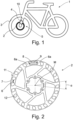
- Fig. 1 shows a schematic representation of an e-bike 1 with a measuring system 5 according to an exemplary embodiment.
- the e-bike 1 is shown here as an (S-)Pedelec.
- the e-bike 1 has two wheels 3 and a stationary component 10, e.g., a fork.
- the measuring system 5 is arranged in the area of the front wheel 3. Alternatively, the measuring system 5 can of course also be arranged on the rear wheel.
- the measuring system 5 is designed as an incremental measuring system 5.
- the measuring system 5 has a measuring ring element 2 and a measuring ring element 2 compatible with the measuring ring element 2.
- the measuring ring element 2 is preferably designed according to one of the embodiments from the Figures 2 to 5 formed.
- the measuring ring element 2 is arranged on the front wheel 3 of the e-bike 1 so that it rotates with the wheel 3.
- the measuring ring element 2 is mounted on the wheel axle of the front wheel 3, with the wheel axle running coaxially to a central axis M of the measuring ring element 2.
- the sensor element 4 is fixed to the fork of the e-bike 1, with the fork representing a stationary component 10 of the e-bike 1.
- measuring ring element 2 performs the same rotational movement. Measuring ring element 2 rotates past sensor element 4. In doing so, sensor element 4 detects the signal generators 6, 6a and the calibration element 8, which measuring ring element 2 has. Sensor element 4 taps signal paths 7 and calibration path 9. Based on this, sensor element 4 generates a sensor signal, which can be forwarded, for example, to a control unit of e-bike 1. Using the generated sensor signal, it is possible to determine the actual rotational speed of wheel 3.
- Fig. 2 shows a schematic representation of a measuring ring element 2 according to an embodiment not claimed.
- the measuring ring element 2 is designed as a circular ring and has a carrier element 11, which carries a plurality of signal transmitters 6, 6a and has the calibration element 8. For clarity, only three signal transmitters are provided with reference numerals. All signal transmitters 6, 6a are of uniform design.
- the calibration element 8 is arranged between two signal transmitters 6a and is delimited by them in the radial direction. All signal transmitters 6, except for the two signal transmitters 6a, between which the calibration element 8 is arranged, are arranged equidistant from one another, with a material-free intermediate space 12 being arranged between every two of these signal transmitters 6.
- the intermediate spaces 12 are all of uniform design.
- the intermediate spaces 12 are shaped as windows here, which is advantageous with regard to the mass of the measuring ring element.
- the calibration element 8 and the signal transmitters 6, 6a are arranged on the support element 11 radially around the central axis M.
- the signal transmitters 6, 6a are arranged largely rotationally symmetrically to the central axis M.
- the measuring ring element 2 has a total of 23 signal transmitters 6, 6a.
- Each of the signal transmitters 6, 6a has a signal path 7 with a certain signal path length.
- the signal paths 7 of all signal transmitters 6, 6a have the same signal path length.
- the signal path length can be as long as the radial distance between two signal transmitters 6 between which no calibration element is arranged.
- the signal transmitters 6, 6a are preferably formed from a magnetic material.
- the calibration element 8 has a calibration section 9 with a calibration section length.
- the calibration section length is longer than a single signal section length.
- the calibration section length is the sum of the signal section length and the distances between two signal transmitters.
- the calibration element 8 is formed as a material-free recess, namely a window, in the support element 11. In other words, the calibration element 8 replaces a signal transmitter 6 including two intermediate spaces 12.
- the calibration section 9 represents a "non-signal section.”
- the positions of the signal transmitters 6, 6a and the calibration element 8 are subject to a regular angular pitch around the circumference of the measuring ring element 2.
- This angular pitch is: 360° / (number of signal transmitters + number of signal transmitters replaced by the calibration element).
- each signal transmitter 6, 6a is offset by 15° from the previous signal transmitter 6, 6a, except for the two signal transmitters 6a between which the calibration element 8 is located.
- the calibration element 8 is arranged directly adjacent to its leading or trailing signal transmitter 6a.
- Fig. 3 shows a schematic representation of a measuring ring element 2 according to a not claimed embodiment.
- the shape of the measuring ring element 2 is very similar to the measuring ring element 2 from Fig. 2 The only difference is the number and arrangement of the signal transmitters 6, 6a and the shape of the calibration element 8.
- shape of the Measuring ring element 3 achieves a higher resolution for the sensor signal to be generated.
- the measuring ring element 2 has a total of 55 signal transmitters 6, 6a.
- Each of the signal transmitters 6, 6a has a signal path 7 with a certain signal path length.
- the signal paths 7 of all signal transmitters 6, 6a have the same signal path length.
- the signal path length can be as long as the radial distance, i.e., the gap 12, between two signal transmitters 6 between which no calibration element is arranged.
- the signal transmitters 6, 6a are preferably formed from a magnetic material.
- the calibration element 8 has a calibration section 9 with a calibration section length.
- the calibration section length is longer than a single signal section length.
- the calibration section length is the sum of the signal section length and the distances between two signal transmitters.
- the calibration element 8 is formed as a material-free recess, namely a window, in the support element 11. In other words, the calibration element 8 replaces a signal transmitter 6 including two intermediate spaces 12.
- the calibration section 9 represents a "non-signal section.”
- the positions of the signal transmitters 6, 6a and the calibration element 8 are subject to a regular angular pitch around the circumference of the measuring ring element 2.
- This angular pitch is: 360° / (number of signal transmitters + number of signal transmitters replaced by the calibration element).
- each signal transmitter 6, 6a is offset by 6.43° from the previous signal transmitter 6, 6a, except for the two signal transmitters 6a between which the calibration element 8 is located.
- the calibration element 8 is arranged directly adjacent to its leading or trailing signal transmitter 6a.
- Fig. 4 shows a schematic representation of a measuring ring element 2 according to a not claimed embodiment.
- the shape of the measuring ring element 2 is very similar to the measuring ring element 2 from Fig. 2 and Fig. 3 The difference is only in the number and arrangement of the signal transmitters 6, 6a and in the shape of the calibration element 8.
- the shape of the measuring ring element 3 shown achieves a higher resolution for the sensor signal to be generated.
- the measuring ring element 2 has a total of 55 signal transmitters 6, 6a.
- Each of the signal transmitters 6, 6a has a signal path 7 with a certain signal path length.
- the signal paths 7 of all signal transmitters 6, 6a have the same signal path length.
- the signal transmitters 6, 6a are preferably formed from a magnetic material.
- the calibration element 8 has a calibration section 9 with a calibration section length.
- the calibration section length is longer than a single signal section length.
- the calibration section length is the sum of the signal section length and the distances between two signal transmitters.
- the calibration element 8 is formed as a material-free recess, namely a window, in the support element 11.
- the calibration element 8 replaces a signal transmitter 6 including an intermediate space 12.
- the calibration section 9 represents a "non-signal section.”
- the positions of the signal transmitters 6, 6a and the calibration element 8 are subject to an irregular angular pitch over the circumference of the measuring ring element 2.
- the calibration element 8 is arranged directly adjacent to its leading or trailing signal transmitter 6a. Due to the irregular angular pitch, it is possible for the calibration section length of the calibration section 9 to be designed to be as long as desired and independent of the signal section lengths of the respective signal sections 7 of the signal transmitters 6, 6a. The irregular angular pitch thus makes it possible to vary the dimensional deviation of the calibration element 8 to a greater extent.
- Fig. 5 shows a schematic representation of a measuring ring element 2 according to an embodiment.
- the shape of the measuring ring element 2 is very similar to the measuring ring element 2 from Fig. 3 .
- the signal generators 6, 6a, the number of signal generators 6, 6a, the arrangement of the signal generators 6, 6a, the signal path lengths, the calibration path length and the regular angular division are formed in the same way as in Fig. 3 .
- the only difference is the shape of the calibration element 8 and the shape of the carrier element 11.
- the carrier element 11 and thus the entire measuring ring element 2 is shaped as a ring segment.
- the calibration element 8 is formed as a material-free recess, namely as a gap, in the support element 11.
- the calibration element 8 has the calibration section 9, which has the calibration section length.
- the calibration section length corresponds to the calibration section length of Fig. 3 .
- the examples shown here are for illustrative purposes only.
- the angular pitch, the number of signal transmitters, the signal path lengths of the signal transmitters, and the calibration path length of the calibration element's calibration path can be adjusted as needed and to achieve the desired resolution.
Landscapes
- Engineering & Computer Science (AREA)
- Mechanical Engineering (AREA)
- Physics & Mathematics (AREA)
- General Physics & Mathematics (AREA)
- Length Measuring Devices With Unspecified Measuring Means (AREA)
Applications Claiming Priority (3)
| Application Number | Priority Date | Filing Date | Title |
|---|---|---|---|
| DE102022202716.7A DE102022202716A1 (de) | 2022-03-21 | 2022-03-21 | Messringelement für ein Messsystem für ein Mikromobilitätsfahrzeug, Messsystem und Mikromobilitätsfahrzeug |
| EP23712196.7A EP4496738A1 (fr) | 2022-03-21 | 2023-03-15 | Élément annulaire de mesure pour un système de mesure pour un véhicule de micromobilité, système de mesure et véhicule de micromobilité |
| PCT/EP2023/056606 WO2023180138A1 (fr) | 2022-03-21 | 2023-03-15 | Élément annulaire de mesure pour un système de mesure pour un véhicule de micromobilité, système de mesure et véhicule de micromobilité |
Related Parent Applications (1)
| Application Number | Title | Priority Date | Filing Date |
|---|---|---|---|
| EP23712196.7A Division EP4496738A1 (fr) | 2022-03-21 | 2023-03-15 | Élément annulaire de mesure pour un système de mesure pour un véhicule de micromobilité, système de mesure et véhicule de micromobilité |
Publications (2)
| Publication Number | Publication Date |
|---|---|
| EP4535010A2 true EP4535010A2 (fr) | 2025-04-09 |
| EP4535010A3 EP4535010A3 (fr) | 2025-06-25 |
Family
ID=85706935
Family Applications (2)
| Application Number | Title | Priority Date | Filing Date |
|---|---|---|---|
| EP25159016.2A Pending EP4535010A3 (fr) | 2022-03-21 | 2023-03-15 | Élément annulaire de mesure pour un système de mesure pour un câble électronique, système de mesure et câble électronique |
| EP23712196.7A Pending EP4496738A1 (fr) | 2022-03-21 | 2023-03-15 | Élément annulaire de mesure pour un système de mesure pour un véhicule de micromobilité, système de mesure et véhicule de micromobilité |
Family Applications After (1)
| Application Number | Title | Priority Date | Filing Date |
|---|---|---|---|
| EP23712196.7A Pending EP4496738A1 (fr) | 2022-03-21 | 2023-03-15 | Élément annulaire de mesure pour un système de mesure pour un véhicule de micromobilité, système de mesure et véhicule de micromobilité |
Country Status (3)
| Country | Link |
|---|---|
| EP (2) | EP4535010A3 (fr) |
| DE (1) | DE102022202716A1 (fr) |
| WO (1) | WO2023180138A1 (fr) |
Families Citing this family (2)
| Publication number | Priority date | Publication date | Assignee | Title |
|---|---|---|---|---|
| DE102024209919A1 (de) | 2024-10-11 | 2026-04-16 | Zf Friedrichshafen Ag | Radeinheit für ein Fahrrad und Fahrrad |
| DE202024105856U1 (de) | 2024-10-11 | 2024-11-13 | Zf Friedrichshafen Ag | Radeinheit für ein Fahrrad und Fahrrad |
Citations (1)
| Publication number | Priority date | Publication date | Assignee | Title |
|---|---|---|---|---|
| EP3590812A1 (fr) | 2018-07-05 | 2020-01-08 | Winora-Staiger GmbH | Système de mesure incrémental pour une bicyclette, bicyclette, moyen émetteur de signal et procédé de fabrication |
Family Cites Families (6)
| Publication number | Priority date | Publication date | Assignee | Title |
|---|---|---|---|---|
| DE19638386A1 (de) | 1996-09-19 | 1998-03-26 | Bayerische Motoren Werke Ag | Stellungsgeber für eine drehbare Welle eines Fahrzeugs |
| US6131547A (en) | 1998-02-27 | 2000-10-17 | Cummins Engine Company, Inc. | Electronic engine speed and position apparatus for camshaft gear applications |
| US8886471B2 (en) | 2008-06-26 | 2014-11-11 | Infineon Technologies Ag | Rotation sensing method and system |
| DE102015120656A1 (de) | 2015-11-27 | 2017-06-01 | Gustav Magenwirth Gmbh & Co. Kg | Radeinheit |
| JP6196345B1 (ja) * | 2016-03-15 | 2017-09-13 | 本田技研工業株式会社 | 車輪速度検出装置 |
| DE102017115157B4 (de) | 2017-07-06 | 2020-03-12 | Saf-Holland Gmbh | Polrad |
-
2022
- 2022-03-21 DE DE102022202716.7A patent/DE102022202716A1/de not_active Ceased
-
2023
- 2023-03-15 EP EP25159016.2A patent/EP4535010A3/fr active Pending
- 2023-03-15 WO PCT/EP2023/056606 patent/WO2023180138A1/fr not_active Ceased
- 2023-03-15 EP EP23712196.7A patent/EP4496738A1/fr active Pending
Patent Citations (1)
| Publication number | Priority date | Publication date | Assignee | Title |
|---|---|---|---|---|
| EP3590812A1 (fr) | 2018-07-05 | 2020-01-08 | Winora-Staiger GmbH | Système de mesure incrémental pour une bicyclette, bicyclette, moyen émetteur de signal et procédé de fabrication |
Also Published As
| Publication number | Publication date |
|---|---|
| DE102022202716A1 (de) | 2023-08-03 |
| EP4535010A3 (fr) | 2025-06-25 |
| EP4496738A1 (fr) | 2025-01-29 |
| WO2023180138A1 (fr) | 2023-09-28 |
Similar Documents
| Publication | Publication Date | Title |
|---|---|---|
| EP2449346B1 (fr) | Capteur angulaire | |
| EP0970000B1 (fr) | Systeme de capteur d'angle de braquage a redondance accrue | |
| EP0848804B1 (fr) | Capteur d'angle absolu de braquage | |
| DE102017125114B4 (de) | Drehmomentsensor und Stator mit mathematisch glatten Klauen | |
| EP1873534B1 (fr) | Dispositif pour déterminer, sans contact, la vitesse de rotation et/ou la position d'un objet doté d'un codeur | |
| EP4535010A2 (fr) | Élément annulaire de mesure pour un système de mesure pour un câble électronique, système de mesure et câble électronique | |
| DE19819664A1 (de) | Vorrichtung zur Bestimmung des Maßes der Verdrehung zwischen zwei Teilen | |
| EP2516978A1 (fr) | Dispositif capteur pour l'enregistrement combiné de vitesse de rotation et de couple | |
| DE19834322B4 (de) | Verfahren und Vorrichtung zur Ermittlung des auf eine Welle wirkenden Drehmoments | |
| EP1706708B1 (fr) | Capteur d'angle de braquage | |
| WO2022135978A1 (fr) | Dispositif de détermination de données pour la détermination de la vitesse d'un véhicule, dispositif d'analyse et procédé associé | |
| EP2901120B1 (fr) | Procédé et dispositif pour déterminer le couple exercé sur un corps rotatif pouvant être entraîné en rotation autour d'un axe de rotation | |
| EP0633545A1 (fr) | Compteur à rouleaux à plusieurs chiffres avec un codeur | |
| DE69632946T2 (de) | Vorrichtung zur Messung der relativen Drehung und/oder Drehgeschwindigkeit zwischen den Laufringen eines Wälzlagers | |
| DE102004009839A1 (de) | Drehwinkelsensor | |
| EP1312534A2 (fr) | Dispositif pour la détermination de l'angle de braquage d'un volant | |
| DE102021106095B4 (de) | Vorrichtung zur Bestimmung der Winkelposition eines Drehelementes | |
| EP4474260A1 (fr) | Roue à impulsions | |
| EP1770375B1 (fr) | Dispositif de mesure de position comprenant deux echelles de mesure dont les pistes codées se chevauchent mutuellement | |
| DE10328753A1 (de) | Vorrichtung zum Messen des Lenkstangenweges einer Kraftfahrzeuglenkung | |
| DE69926027T2 (de) | Dreh-Übertrager für ein Kraftfahrzeug mit verkürztem Flachbandleiter | |
| EP3021088B1 (fr) | Système de mesure de longueur incrémental et son procédé de fonctionnement | |
| DE19836666C1 (de) | Lenkwinkelsensor | |
| DE102024209919A1 (de) | Radeinheit für ein Fahrrad und Fahrrad | |
| DE102007049977B3 (de) | Inkrementale Messeinrichtung zur Erfassung von Drehzahl, Drehrichtung und der Axialposition von axial verschieblichen Zahnrädern |
Legal Events
| Date | Code | Title | Description |
|---|---|---|---|
| PUAI | Public reference made under article 153(3) epc to a published international application that has entered the european phase |
Free format text: ORIGINAL CODE: 0009012 |
|
| STAA | Information on the status of an ep patent application or granted ep patent |
Free format text: STATUS: THE APPLICATION HAS BEEN PUBLISHED |
|
| AC | Divisional application: reference to earlier application |
Ref document number: 4496738 Country of ref document: EP Kind code of ref document: P |
|
| AK | Designated contracting states |
Kind code of ref document: A2 Designated state(s): AL AT BE BG CH CY CZ DE DK EE ES FI FR GB GR HR HU IE IS IT LI LT LU LV MC ME MK MT NL NO PL PT RO RS SE SI SK SM TR |
|
| REG | Reference to a national code |
Ref country code: DE Ref legal event code: R079 Free format text: PREVIOUS MAIN CLASS: G01P0003000000 Ipc: B62J0045412000 |
|
| PUAL | Search report despatched |
Free format text: ORIGINAL CODE: 0009013 |
|
| AK | Designated contracting states |
Kind code of ref document: A3 Designated state(s): AL AT BE BG CH CY CZ DE DK EE ES FI FR GB GR HR HU IE IS IT LI LT LU LV MC ME MK MT NL NO PL PT RO RS SE SI SK SM TR |
|
| RIC1 | Information provided on ipc code assigned before grant |
Ipc: G01P 3/487 20060101ALI20250521BHEP Ipc: G01P 3/481 20060101ALI20250521BHEP Ipc: B62L 1/00 20060101ALI20250521BHEP Ipc: B62J 45/423 20200101ALI20250521BHEP Ipc: B62J 45/413 20200101ALI20250521BHEP Ipc: B62J 45/412 20200101AFI20250521BHEP |
|
| STAA | Information on the status of an ep patent application or granted ep patent |
Free format text: STATUS: REQUEST FOR EXAMINATION WAS MADE |
|
| 17P | Request for examination filed |
Effective date: 20251204 |