EP4535564A1 - Rekonfigurierbare antenne - Google Patents
Rekonfigurierbare antenne Download PDFInfo
- Publication number
- EP4535564A1 EP4535564A1 EP24204432.9A EP24204432A EP4535564A1 EP 4535564 A1 EP4535564 A1 EP 4535564A1 EP 24204432 A EP24204432 A EP 24204432A EP 4535564 A1 EP4535564 A1 EP 4535564A1
- Authority
- EP
- European Patent Office
- Prior art keywords
- antenna
- amplifier
- network
- reconfigurable
- elementary
- Prior art date
- Legal status (The legal status is an assumption and is not a legal conclusion. Google has not performed a legal analysis and makes no representation as to the accuracy of the status listed.)
- Granted
Links
Images
Classifications
-
- H—ELECTRICITY
- H01—ELECTRIC ELEMENTS
- H01Q—ANTENNAS, i.e. RADIO AERIALS
- H01Q3/00—Arrangements for changing or varying the orientation or the shape of the directional pattern of the waves radiated from an antenna or antenna system
- H01Q3/44—Arrangements for changing or varying the orientation or the shape of the directional pattern of the waves radiated from an antenna or antenna system varying the electric or magnetic characteristics of reflecting, refracting, or diffracting devices associated with the radiating element
- H01Q3/46—Active lenses or reflecting arrays
-
- H—ELECTRICITY
- H04—ELECTRIC COMMUNICATION TECHNIQUE
- H04B—TRANSMISSION
- H04B1/00—Details of transmission systems, not covered by a single one of groups H04B3/00 - H04B13/00; Details of transmission systems not characterised by the medium used for transmission
- H04B1/005—Details of transmission systems, not covered by a single one of groups H04B3/00 - H04B13/00; Details of transmission systems not characterised by the medium used for transmission adapting radio receivers, transmitters andtransceivers for operation on two or more bands, i.e. frequency ranges
- H04B1/0067—Details of transmission systems, not covered by a single one of groups H04B3/00 - H04B13/00; Details of transmission systems not characterised by the medium used for transmission adapting radio receivers, transmitters andtransceivers for operation on two or more bands, i.e. frequency ranges with one or more circuit blocks in common for different bands
- H04B1/0075—Details of transmission systems, not covered by a single one of groups H04B3/00 - H04B13/00; Details of transmission systems not characterised by the medium used for transmission adapting radio receivers, transmitters andtransceivers for operation on two or more bands, i.e. frequency ranges with one or more circuit blocks in common for different bands using different intermediate frequencied for the different bands
- H04B1/0078—Details of transmission systems, not covered by a single one of groups H04B3/00 - H04B13/00; Details of transmission systems not characterised by the medium used for transmission adapting radio receivers, transmitters andtransceivers for operation on two or more bands, i.e. frequency ranges with one or more circuit blocks in common for different bands using different intermediate frequencied for the different bands with a common intermediate frequency amplifier for the different intermediate frequencies, e.g. when using switched intermediate frequency filters
-
- H—ELECTRICITY
- H01—ELECTRIC ELEMENTS
- H01Q—ANTENNAS, i.e. RADIO AERIALS
- H01Q13/00—Waveguide horns or mouths; Slot antennas; Leaky-waveguide antennas; Equivalent structures causing radiation along the transmission path of a guided wave
- H01Q13/02—Waveguide horns
-
- H—ELECTRICITY
- H01—ELECTRIC ELEMENTS
- H01Q—ANTENNAS, i.e. RADIO AERIALS
- H01Q21/00—Antenna arrays or systems
- H01Q21/29—Combinations of different interacting antenna units for giving a desired directional characteristic
Definitions
- This description relates generally to electronic devices, more particularly to reconfigurable antennas.
- each elementary cell is capable of compensating for each path difference between the focal source(s) and the radiating aperture.
- the elementary cells can only compensate for a limited number of phase states, for example 2 N phase states, with N a positive integer, in the case of N-bit phase quantization compensation.
- the same transmitter network can alternate between transmission and reception phases, provided that it is devoid of non-reciprocal elements such as amplifiers or attenuators. Otherwise, the transmitter network can only operate in transmission or reception.
- Transmitting array antennas suffer from various drawbacks.
- existing transmitting array antennas have a relatively large thickness, imposed by a need to distance the focal source(s) from the transmitting array.
- each first elementary cell comprises at least one first antenna element located opposite the transmitter network.
- each first elementary cell further comprises at least one amplifier connected to said at least one first antenna element.
- each second elementary cell comprises a second antenna element intended to reflect, in the direction of the amplifier network, a signal coming from said at least one source and/or to reflect, in the direction of said at least one source, a signal coming from the amplifier network.
- each first cell is adapted to operate a polarization rotation.
- said at least one source is a single horn antenna.
- insulator and “conductor” mean respectively, except contrary precision, electrically insulating and electrically conductive.
- the antenna 100 typically comprises one or more primary sources 101 (a single source 101, in the example shown) irradiating a transmitting network 105.
- the source 101 may have any polarization, for example linear or circular.
- the network 105 comprises a plurality of elementary cells 107, for example arranged in a matrix according to rows and columns. Each cell 107 typically comprises a first antenna element 107a, located on the side of a first face of the network 105 arranged opposite the primary source 101, and a second antenna element 107b, located on the side of a second face of the network opposite the first face.
- the second face of the network 105 is for example turned towards a transmission medium, or external medium, of the antenna 100.
- Each cell 107 is capable, in transmission, of receiving electromagnetic radiation on its first antenna element 107a and of re-emitting this radiation from its second antenna element 107b, for example by introducing a known phase shift ⁇ .
- each cell 107 is capable of receiving electromagnetic radiation on its second antenna element 107b and of re-emitting this radiation from its first antenna element 107a, in the direction of the source 101, with the same phase shift ⁇ .
- the radiation re-emitted by the first antenna element 107a is for example focused on the source 101.
- transceiver array antennas are energy efficient and relatively simple, inexpensive, and compact. This is due in part to the fact that transceiver arrays can be built using planar technology, usually on a printed circuit board.
- the present description relates more particularly to antennas with a reconfigurable transmitter array 105 and a fixed beam.
- the transmitter array 105 is said to be reconfigurable when the elementary cells 107 are electronically controllable individually to modify their phase shift value ⁇ and/or their amplitude, which makes it possible to dynamically modify the characteristics of the radiation generated by the antenna, and in particular to modify its pointing direction without mechanically moving the antenna or a part of the antenna by means of a motorized element.
- the primary source 101 is connected to a circuit 109.
- the circuit 109 is for example a transmission and/or reception circuit intended respectively to produce signals to be transmitted by the reconfigurable antenna 100 and/or to process signals received by the reconfigurable antenna 100.
- This example is however not limiting, the circuit 109 being able to further implement additional functions such as analog-digital conversion, filtering, impedance adaptation, interference elimination functions, etc.
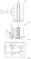
- FIG. 2 is a schematic and partial side view of a reconfigurable antenna 200 according to one embodiment.
- the antenna 200 of the Figure 2 includes common elements with the 100 antenna of the Figure 1 These common elements will not be detailed again below.
- the source 101 is configured to irradiate, or to be irradiated by, the transmitter network 105
- the amplifier network 201 is configured to irradiate and to be irradiated by the transmitter network 105.
- the elementary cells 203 of the amplifier network 201 are for example arranged in a matrix according to rows and columns. Furthermore, the elementary cells 203 are for example substantially located in the same plane, the network 201 being in this case of the planar type.
- Each elementary cell 203 comprises at least one antenna element 203b (two antenna elements 203b, in the example shown) located on the side of a face of the amplifier network 201 arranged opposite the transmitter network 105.
- Each elementary cell 203 further comprises an amplification circuit 205 (symbolized, in Figure 2 , by a square) connected to the antenna element or elements 203b of the cell.
- the amplifier network 201 is produced in planar technology, for example on a printed circuit board.
- the amplifier network 201 of the reconfigurable antenna 200 comprises for example a number of antenna elements 203b equal to the number of first antenna elements 107a of the transmitter network 105, each antenna element 203b of the amplifier network 201 being for example located opposite one of the first antenna elements 107a of the transmitter network 105.
- this example is not limiting and the amplifier network 201 may, as a variant, comprise a number of antenna elements 203b strictly less than or strictly greater than the number of first antenna elements 107a of the transmitter network 105.
- the elementary cells 107 of the transmitter network 105 are for example substantially located in the same plane, for example a plane substantially parallel to the plane of the amplifier network 201. Each elementary cell 107 of the transmitter network 105 is for example separated from the adjacent elementary cells 107 by a distance equal to approximately half a central transmission and/or reception wavelength of the antenna 200.
- the reconfigurable antenna 200 comprises a number of elementary cells 203 strictly less than the number of elementary cells 107.
- the reconfigurable antenna 200 being able, as a variant, to comprise a number of elementary cells 203 equal to or strictly greater than the number of elementary cells 107.
- the reconfigurable antenna 200 comprises four, nine or sixteen times fewer amplification circuits 205 than elementary cells 107, each elementary cell 203 then comprising for example respectively four, nine or sixteen antenna elements 203b.
- the reconfigurable antenna 200 can of course comprise numbers of elementary cells 203 and elementary cells 107 different from those represented, for example several tens, several hundreds or several thousands of elementary cells 203 and elementary cells 105.
- the second antenna elements 107b of the elementary cells 107 have a linear polarization parallel or orthogonal to the polarization of the first elementary cells 107a.
- the second antenna elements 107b of the elementary cells 107 have circular polarization.
- each elementary cell 203 of the amplifier network 201 is capable of receiving, on its antenna element 203b or one of its antenna elements 203b, electromagnetic radiation originating from the reflection, on the first antenna elements 107a of the elementary cells 107 of the transmitter network 105, and of transmitting, from its antenna element 203b or another of its antenna elements 203b, amplified electromagnetic radiation of modified polarization in the direction of the transmitter network 105.
- the elementary cells 203 are for example capable of carrying out a polarization rotation, for example of the order of 90°, between the received radiation and the re-emitted radiation.
- the electromagnetic radiation re-emitted by the elementary cells 203 of the amplifier network 201 has, for example, a polarization substantially parallel to that of the first antenna elements 107a of the elementary cells 107 of the transmitter network 105.
- Each cell 107 is capable, in transmission, of receiving, on its first antenna element 107a, electromagnetic radiation coming from the amplifier network 201 and of re-emitting this radiation, from its second antenna element 107b, for example by introducing a known phase shift ⁇ .
- the characteristics of the near-field or far-field radiation produced by the antenna 200 in particular its shape (or size), its intensity and its maximum emission direction (or pointing direction), depend on the values of the phase shifts respectively introduced by the different elementary cells 107 of the transmitter network 105.
- each elementary cell 107 of the transmitter network 105 is capable of receiving, on its second antenna element 107b, electromagnetic radiation coming from the external environment and of re-emitting this radiation, from its first antenna element 107a, in the direction of the elementary cells 203 of the amplifier network 201, with the phase shift ⁇ .
- each elementary cell 203 of the amplifier network 201 is capable of receiving, on its antenna element 203b or one of its antenna elements 203b, electromagnetic radiation coming from the transmitter network 105 and of emitting, from its antenna element 203b or another of its antenna elements 203b, amplified electromagnetic radiation of modified polarization in the direction of the transmitter network 105.
- the electromagnetic radiation re-emitted by the elementary cells 203 of the amplifier network 201 has, for example, a polarization substantially orthogonal to that of the first antenna elements 107a of the elementary cells 107 of the transmitter network 105.
- each cell 107 is capable of receiving electromagnetic radiation coming from the amplifier network 201 on its first antenna element 107a, and of re-emitting this radiation from its first antenna element 107a.
- the first antenna element 107a makes it possible, for example, to reflect the electromagnetic radiation coming from the amplifier network 201 in the direction of the source 101.
- Each elementary cell 107 comprises for example a phase shift circuit of which a first terminal is connected to the first antenna element 107a, located opposite the source 101 and towards the amplifier network 201, and of which a second terminal is connected to the second antenna element 107b, facing the external environment.
- the phase shift circuit is for example configured to apply a phase shift ⁇ between the signal received by the antenna element 107a and the signal emitted by the antenna element 107b, in the case where the reconfigurable antenna 200 operates in transmission, or to apply the phase shift ⁇ between the signal received by the antenna element 107b and the signal emitted by the antenna element 107a, in the case where the reconfigurable antenna 200 operates in reception.
- each elementary cell 107 is configured to introduce a phase shift ⁇ between the signals received or transmitted by the antenna element 107a and the signals transmitted or received by the antenna element 107b.
- the elementary cell being able, as a variant or as a complement, to implement other functions, for example a polarization state change function allowing to switch from a signal having a left circular polarization to a signal having a right circular polarization.
- each elementary cell 107 of the reconfigurable transmitter network 105 has a structure identical or analogous to the elementary cell of the transmitter network described in the patent application EP 4117117 , the cell then being for example adapted to switch between two polarization states and four phase states.
- the elementary cell 203 comprises a switch 301, for example a single-pole double-throw (SPDT) switch.
- the switch 301 more precisely comprises an input connected to a circuit 303, a first output connected to an input of a first amplifier 305 (PA), and a second output connected to an output of a second amplifier 307 (LNA).
- the switch 301 receives, for example, a control signal to connect its input to its first output, when the reconfigurable antenna 200 is used in transmission, and to its second output, when the reconfigurable antenna 200 is used in reception.
- the amplifier 305 of the elementary cell 203 is for example intended to amplify a signal emitted by the antenna 200.
- the amplifier 305 is a power amplifier, for example a class A linear amplifier in CMOS (Complementary Metal-Oxide-Semiconductor) SOI (Silicon On-chip) technology. Insulator » - silicon on insulator), for example of the type described in the article by A. Hamani, A. Siligaris, B.
- the amplifier 307 of the elementary cell 203 is for example intended to amplify a signal received by the antenna 200.
- the amplifier 307 is a low noise amplifier (LNA). This makes it possible to optimize a noise factor of the elementary cell 203 when it is used for reception.
- the amplifier 307 comprises a class “AB” amplifier comprising for example one or two operating stages.
- the amplifier 307 has for example an electrical power of between 10 and 20 mW.
- the elementary cell 203 comprises another switch 309, for example a single pole double throw (SPDT) switch.
- the switch 309 more precisely comprises an input connected to a circuit 311, a first output connected to an output of the first amplifier 305, and a second output connected to an input of the second amplifier 307.
- the switch 309 receives, for example, a control signal to connect its input to its first output, when the reconfigurable antenna 200 is used in transmission, and to its second output, when the reconfigurable antenna 200 is used in reception.
- An advantage of the reconfigurable antenna 200 lies in the fact that the presence of the amplifier network 201 advantageously makes it possible to bring the primary source 101 closer to the transmitter network 105. In other words, this makes it possible to “fold” the source of the antenna 200 compared to the case of the antenna 100.
- the antenna 200 thus has a thickness that is less, for example of the order of three times less, than that which a comparable transmitter network antenna, for example the antenna 100, would have. This also provides the advantage, compared to a transmitter network antenna of the type of the antenna 100, of facilitating the production of systems for amplifying the radiofrequency signal transmitted or received.
- the practical implementation of the embodiments and variants described is within the reach of the person skilled in the art from the functional indications given above.
- the practical realization of the antenna element(s), the switches and the amplifier(s) of the elementary cells of the amplifier network 201 as well as the practical realization of the elementary cells of the transmitter network 105 are within the reach of the person skilled in the art from the indications of the present description.
- the person skilled in the art is furthermore capable of adjusting the number of antenna elements 203b of each elementary cell 203 of the amplifier network 201, in particular as a function of the proportion of elementary cells 203 of the amplifier network 201 relative to the elementary cells 107 of the transmitter network 105.
Landscapes
- Engineering & Computer Science (AREA)
- Computer Networks & Wireless Communication (AREA)
- Signal Processing (AREA)
- Variable-Direction Aerials And Aerial Arrays (AREA)
- Transmitters (AREA)
Applications Claiming Priority (1)
| Application Number | Priority Date | Filing Date | Title |
|---|---|---|---|
| FR2310684A FR3153940B1 (fr) | 2023-10-05 | 2023-10-05 | Antenne reconfigurable |
Publications (2)
| Publication Number | Publication Date |
|---|---|
| EP4535564A1 true EP4535564A1 (de) | 2025-04-09 |
| EP4535564B1 EP4535564B1 (de) | 2026-01-14 |
Family
ID=89573469
Family Applications (1)
| Application Number | Title | Priority Date | Filing Date |
|---|---|---|---|
| EP24204432.9A Active EP4535564B1 (de) | 2023-10-05 | 2024-10-03 | Rekonfigurierbare antenne |
Country Status (3)
| Country | Link |
|---|---|
| US (1) | US20250286567A2 (de) |
| EP (1) | EP4535564B1 (de) |
| FR (1) | FR3153940B1 (de) |
Citations (2)
| Publication number | Priority date | Publication date | Assignee | Title |
|---|---|---|---|---|
| EP1041673A2 (de) * | 1999-04-01 | 2000-10-04 | Space Systems / Loral, Inc. | Aktive Mehrfachstrahlenantennen |
| EP4117117A1 (de) | 2021-07-07 | 2023-01-11 | Commissariat À L'Énergie Atomique Et Aux Énergies Alternatives | Antennenzelle mit sendenetz |
Family Cites Families (5)
| Publication number | Priority date | Publication date | Assignee | Title |
|---|---|---|---|---|
| FR2729505A1 (fr) * | 1995-01-18 | 1996-07-19 | Alcatel Espace | Antenne multifaisceaux forte capacite a balayage electronique en emission |
| US6889061B2 (en) * | 2000-01-27 | 2005-05-03 | Celletra Ltd. | System and method for providing polarization matching on a cellular communication forward link |
| US20190036215A1 (en) * | 2017-07-25 | 2019-01-31 | Huawei Technologies Co., Ltd. | System and method for beamforming using a phased array antenna |
| US11437803B2 (en) * | 2020-04-21 | 2022-09-06 | Textron Innovations Inc. | Methods and systems for active lightning prevention |
| US12143144B2 (en) * | 2021-03-25 | 2024-11-12 | Skyworks Solutions, Inc. | Antenna arrays with multiple feeds and varying pitch for wideband frequency coverage |
-
2023
- 2023-10-05 FR FR2310684A patent/FR3153940B1/fr active Active
-
2024
- 2024-10-03 EP EP24204432.9A patent/EP4535564B1/de active Active
- 2024-10-03 US US18/906,135 patent/US20250286567A2/en active Pending
Patent Citations (2)
| Publication number | Priority date | Publication date | Assignee | Title |
|---|---|---|---|---|
| EP1041673A2 (de) * | 1999-04-01 | 2000-10-04 | Space Systems / Loral, Inc. | Aktive Mehrfachstrahlenantennen |
| EP4117117A1 (de) | 2021-07-07 | 2023-01-11 | Commissariat À L'Énergie Atomique Et Aux Énergies Alternatives | Antennenzelle mit sendenetz |
Non-Patent Citations (3)
| Title |
|---|
| A. HAMANIA. SILIGARISB. BLAMPEYJ. L. G. JIMENEZ: "167-GHz and 155-GHz High Gain D-band Power Amplifiers in CMOS SOI 45-nm Technology", EUROPEAN MICROWAVE INTEGRATED CIRCUITS CONFERENCE (EUMIC) » À UTRECHT, PAYS-BAS DE, 2021, pages 261 - 264 |
| LANDSBERG NAFTALI ET AL: "Design and Measurements of 100 GHz Reflectarray and Transmitarray Active Antenna Cells", IEEE TRANSACTIONS ON ANTENNAS AND PROPAGATION, IEEE, USA, vol. 65, no. 12, 1 December 2017 (2017-12-01) - 1 December 2017 (2017-12-01), pages 6986 - 6997, XP011673503, ISSN: 0018-926X, [retrieved on 20171128], DOI: 10.1109/TAP.2017.2759840 * |
| PAN WENBO ET AL: "An Amplifying Tunable Transmitarray Element", IEEE ANTENNAS AND WIRELESS PROPAGATION LETTERS, vol. 13, 2014 - 2014, pages 702 - 705, XP011545949, ISSN: 1536-1225, [retrieved on 20140418], DOI: 10.1109/LAWP.2014.2313596 * |
Also Published As
| Publication number | Publication date |
|---|---|
| US20250286567A2 (en) | 2025-09-11 |
| EP4535564B1 (de) | 2026-01-14 |
| FR3153940B1 (fr) | 2025-08-29 |
| US20250119168A1 (en) | 2025-04-10 |
| FR3153940A1 (fr) | 2025-04-11 |
Similar Documents
| Publication | Publication Date | Title |
|---|---|---|
| EP3392959B1 (de) | Grundzelle eines übertragungsnetzes für eine rekonfigurierbare antenne | |
| EP2532046B1 (de) | Flachplatten-abtastantenne für landfahrzeuganwendung, fahrzeug mit einer solchen antenne und satellitentelekommunikationssystem mit solch einem fahrzeug | |
| CA2053643C (fr) | Dispositif d'alimentation d'un element rayonnant fonctionnant en double polarisation | |
| EP2194602B1 (de) | Antenne mit gemeinsam benützten Elementarstrahlern und Verfahren zum Entwurf einer Mehrstrahlantenne mit gemeinsam benützten Elementarstrahlern | |
| EP2807702B1 (de) | Zweidimensionaler mehrstrahlformer, antenne mit einem solchen mehrstrahlformer und satellitentelekommunikationssystem mit einer derartigen antenne | |
| EP3011639B1 (de) | Speiseanordnung für eine parabolantenne | |
| EP4117117B1 (de) | Antennenzelle mit sendenetz | |
| EP3176875A1 (de) | Aufbau einer aktiven hybriden rekonfigurierbaren strahlbildungsantenne | |
| EP0734093A1 (de) | Vorrichtung zur Speisung einer Mehrstrahl-Gruppenantenne | |
| WO1999060661A1 (fr) | Dispositif d'emission et de reception d'ondes hyperfrequences polarisees circulairement | |
| EP3832899A1 (de) | Drahtloser sender, der frequenzmultiplexing von kanälen ausführt | |
| FR2829297A1 (fr) | Reseau formateur de faisceaux, vehicule spatial, systeme associe et methode de formation de faisceaux | |
| EP4092831B1 (de) | Antenne mit lückenhaftem verteilungsnetz | |
| EP4535564B1 (de) | Rekonfigurierbare antenne | |
| FR2965980A1 (fr) | Reseau d'antennes pour dispositif d'emission/reception de signaux de longueur d'onde du type micro-onde, millimetrique ou terahertz | |
| EP4560832A1 (de) | Antennenzelle mit sendernetzwerk | |
| EP4535565A1 (de) | Rekonfigurierbare antenne | |
| EP4523291B1 (de) | Flache antenne mit zweidimensionaler elektronischer abtastung | |
| US20180138879A1 (en) | Method in Wireless Receiver for Using Reduced Number of Phase Shifters | |
| EP4087060A1 (de) | Antennenzelle mit sendernetz | |
| FR3151945A1 (fr) | Antenne à réseau transmetteur | |
| EP4421992A1 (de) | Antennenzelle mit sendernetzwerk | |
| WO2025119848A1 (fr) | Antenne radioelectrique double bande | |
| FR3152094A1 (fr) | Système antennaire et antenne réseau correspondante | |
| WO2025247699A1 (fr) | Cellule polarisante active, réseau transmetteur et antennes d'émission et de réception radio |
Legal Events
| Date | Code | Title | Description |
|---|---|---|---|
| PUAI | Public reference made under article 153(3) epc to a published international application that has entered the european phase |
Free format text: ORIGINAL CODE: 0009012 |
|
| STAA | Information on the status of an ep patent application or granted ep patent |
Free format text: STATUS: REQUEST FOR EXAMINATION WAS MADE |
|
| 17P | Request for examination filed |
Effective date: 20241003 |
|
| AK | Designated contracting states |
Kind code of ref document: A1 Designated state(s): AL AT BE BG CH CY CZ DE DK EE ES FI FR GB GR HR HU IE IS IT LI LT LU LV MC ME MK MT NL NO PL PT RO RS SE SI SK SM TR |
|
| GRAP | Despatch of communication of intention to grant a patent |
Free format text: ORIGINAL CODE: EPIDOSNIGR1 |
|
| STAA | Information on the status of an ep patent application or granted ep patent |
Free format text: STATUS: GRANT OF PATENT IS INTENDED |
|
| RIC1 | Information provided on ipc code assigned before grant |
Ipc: H01Q 3/46 20060101AFI20250812BHEP |
|
| INTG | Intention to grant announced |
Effective date: 20250903 |
|
| GRAS | Grant fee paid |
Free format text: ORIGINAL CODE: EPIDOSNIGR3 |
|
| GRAA | (expected) grant |
Free format text: ORIGINAL CODE: 0009210 |
|
| STAA | Information on the status of an ep patent application or granted ep patent |
Free format text: STATUS: THE PATENT HAS BEEN GRANTED |
|
| AK | Designated contracting states |
Kind code of ref document: B1 Designated state(s): AL AT BE BG CH CY CZ DE DK EE ES FI FR GB GR HR HU IE IS IT LI LT LU LV MC ME MK MT NL NO PL PT RO RS SE SI SK SM TR |
|
| REG | Reference to a national code |
Ref country code: CH Ref legal event code: F10 Free format text: ST27 STATUS EVENT CODE: U-0-0-F10-F00 (AS PROVIDED BY THE NATIONAL OFFICE) Effective date: 20260114 Ref country code: GB Ref legal event code: FG4D Free format text: NOT ENGLISH |
|
| REG | Reference to a national code |
Ref country code: DE Ref legal event code: R096 Ref document number: 602024002056 Country of ref document: DE |
|
| REG | Reference to a national code |
Ref country code: IE Ref legal event code: FG4D Free format text: LANGUAGE OF EP DOCUMENT: FRENCH |