EP4535677A1 - Nfc-vorrichtung - Google Patents
Nfc-vorrichtung Download PDFInfo
- Publication number
- EP4535677A1 EP4535677A1 EP24202456.0A EP24202456A EP4535677A1 EP 4535677 A1 EP4535677 A1 EP 4535677A1 EP 24202456 A EP24202456 A EP 24202456A EP 4535677 A1 EP4535677 A1 EP 4535677A1
- Authority
- EP
- European Patent Office
- Prior art keywords
- type
- field communication
- antenna
- nfc
- mode
- Prior art date
- Legal status (The legal status is an assumption and is not a legal conclusion. Google has not performed a legal analysis and makes no representation as to the accuracy of the status listed.)
- Pending
Links
Images

Classifications
-
- H—ELECTRICITY
- H04—ELECTRIC COMMUNICATION TECHNIQUE
- H04B—TRANSMISSION
- H04B5/00—Near-field transmission systems, e.g. inductive or capacitive transmission systems
- H04B5/40—Near-field transmission systems, e.g. inductive or capacitive transmission systems characterised by components specially adapted for near-field transmission
- H04B5/48—Transceivers
-
- G—PHYSICS
- G06—COMPUTING OR CALCULATING; COUNTING
- G06K—GRAPHICAL DATA READING; PRESENTATION OF DATA; RECORD CARRIERS; HANDLING RECORD CARRIERS
- G06K7/00—Methods or arrangements for sensing record carriers, e.g. for reading patterns
- G06K7/10—Methods or arrangements for sensing record carriers, e.g. for reading patterns by electromagnetic radiation, e.g. optical sensing; by corpuscular radiation
- G06K7/10009—Methods or arrangements for sensing record carriers, e.g. for reading patterns by electromagnetic radiation, e.g. optical sensing; by corpuscular radiation sensing by radiation using wavelengths larger than 0.1 mm, e.g. radio-waves or microwaves
- G06K7/10237—Methods or arrangements for sensing record carriers, e.g. for reading patterns by electromagnetic radiation, e.g. optical sensing; by corpuscular radiation sensing by radiation using wavelengths larger than 0.1 mm, e.g. radio-waves or microwaves the reader and the record carrier being capable of selectively switching between reader and record carrier appearance, e.g. in near field communication [NFC] devices where the NFC device may function as an RFID reader or as an RFID tag
-
- G—PHYSICS
- G06—COMPUTING OR CALCULATING; COUNTING
- G06K—GRAPHICAL DATA READING; PRESENTATION OF DATA; RECORD CARRIERS; HANDLING RECORD CARRIERS
- G06K19/00—Record carriers for use with machines and with at least a part designed to carry digital markings
- G06K19/06—Record carriers for use with machines and with at least a part designed to carry digital markings characterised by the kind of the digital marking, e.g. shape, nature, code
- G06K19/067—Record carriers with conductive marks, printed circuits or semiconductor circuit elements, e.g. credit or identity cards also with resonating or responding marks without active components
- G06K19/07—Record carriers with conductive marks, printed circuits or semiconductor circuit elements, e.g. credit or identity cards also with resonating or responding marks without active components with integrated circuit chips
- G06K19/0723—Record carriers with conductive marks, printed circuits or semiconductor circuit elements, e.g. credit or identity cards also with resonating or responding marks without active components with integrated circuit chips the record carrier comprising an arrangement for non-contact communication, e.g. wireless communication circuits on transponder cards, non-contact smart cards or RFIDs
-
- G—PHYSICS
- G06—COMPUTING OR CALCULATING; COUNTING
- G06K—GRAPHICAL DATA READING; PRESENTATION OF DATA; RECORD CARRIERS; HANDLING RECORD CARRIERS
- G06K19/00—Record carriers for use with machines and with at least a part designed to carry digital markings
- G06K19/06—Record carriers for use with machines and with at least a part designed to carry digital markings characterised by the kind of the digital marking, e.g. shape, nature, code
- G06K19/067—Record carriers with conductive marks, printed circuits or semiconductor circuit elements, e.g. credit or identity cards also with resonating or responding marks without active components
- G06K19/07—Record carriers with conductive marks, printed circuits or semiconductor circuit elements, e.g. credit or identity cards also with resonating or responding marks without active components with integrated circuit chips
- G06K19/077—Constructional details, e.g. mounting of circuits in the carrier
- G06K19/07749—Constructional details, e.g. mounting of circuits in the carrier the record carrier being capable of non-contact communication, e.g. constructional details of the antenna of a non-contact smart card
- G06K19/07773—Antenna details
- G06K19/07775—Antenna details the antenna being on-chip
Definitions
- Near-field communications are generally standardized or meet specifications set by stakeholders in the field.
- the NFC Forum sets specifications that communication devices must meet to communicate with each other, depending, for example, on the application or the nature of the exchanges (payment, access control, authentication, file sharing, etc.).
- the device capable of being associated in a lasting manner can be an accessory attached to the mobile device, for example a communicating shell that displays the time, an electronic wallet, etc.
- the accessory generally uses the near-field communication mode to be recognized (paired or authenticated), in card mode, by the mobile phone operating as a reader but then communicates functionally with the latter by a connection of another nature, for example Bluetooth, Wifi, etc.
- the fact that the accessory is in card mode can cause, when the mobile phone must establish another communication in card mode with a remote reader, that the remote reader sees two "cards" and then refuses the communication. Such a situation is likely to occur, for example, with a payment terminal that perceives two card-type communication devices in its field (the phone and its shell).
- One embodiment overcomes all or part of the drawbacks of conventional near-field communication devices. More particularly, one embodiment aims to ensure that the presence of permanent NFC accessories or devices does not disrupt the operation of a mobile device carrying this accessory.
- communication with the first type of device is carried out in reader or card mode.
- the identification of a device of the second type is carried out by a microcontroller of the device, distinct from the router, the microcontroller storing a unique identifier of the device of the second type.
- the microcontroller if no device of the first or second type is detected during a polling frame, the microcontroller erases any unique identifier of a device of the second type present in memory.
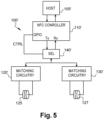
- the antenna comprises two loops electrically in series, respectively intended for devices of the first and second type.
- the loop intended for devices of the second type surrounds or is surrounded by a magnet for aligning the respective antennas of the apparatus and the device of the second type.
- the expressions "about”, “approximately”, “substantially”, and “of the order of” mean to within 10%, preferably to within 5%.
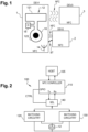
- FIG. 1 represents, very schematically and in the form of blocks, an embodiment of a near-field communication system according to a first aspect.
- a mobile phone 1 capable of being associated with an accessory 2 (DEV2) of the communicating phone case type
- DEV1 mobile phone 1
- DEV2 mobile phone 2
- This element could, before starting charging, request authentication using NFC technology.
- This element is for example a stylus or a connected bracelet ("fitness band" in English).
- Another example is a battery capable of recharging the phone: before recharging the phone by wireless energy transfer, this battery is for example authenticated by NFC.
- the phone In the context of exchanges between phone 1 and its accessory 2, the phone operates in reader mode and the accessory in card mode.
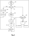
- the Figure 2 represents a device 100 of the mobile telephone 1 according to one embodiment, connected to the antenna 12.
- the antenna 12 is generally associated with one or more capacitive elements not shown (internal and/or external to the device 100) to form an oscillating circuit controlled by the device 100.
- the device 100 comprises various digital and analog electronic circuits depending on its application.
- its NFC device is based on an NFC router (or controller) controlled by a host circuit or microcontroller 105 (HOST).
- the NFC controller serves as an interface between the digital circuits of the telephone and the radiofrequency transceiver oscillating circuit.
- the antenna 12 is adapted to communicate with different devices 2 and 3 depending on the loop used.
- the device 100 comprises, between the NFC controller 110 and the antenna, two impedance matching circuits 120 and 130 and a selector 140 (SEL) to direct the signals to be transmitted Tx or received Rx to one or other of the circuits 120 and 130 depending on the operating mode chosen.
- SEL selector 140
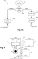
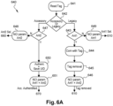
- This 360 calibration is also performed if, at block 310, neither field nor electronic tag is detected (output N of block 310). This may mean that a previously present and registered accessory is no longer in relation with the device 1. Its identifier, which had been recorded during its detection, is then erased from the device's memory (block 390, "All known UID clear") and then a calibration is performed. If necessary, information is sent to the host circuit 105 (HOST) for potential notification to the user of the device that the accessory is no longer detected.
- HOST host circuit 105
- the selector 140' makes it possible to direct, towards one or the other of the antennas 125 and 127, NFC signals to be transmitted by the NFC device 1 comprising the circuit 100' depending on the remote device 2 or 3 with which the mobile telephone 1 wishes to communicate.
- the selector 140' is an antenna selector, each antenna being associated with its impedance matching circuit.
- the selector is connected, in the same way as in Figure 2 , to the NFC controller 110' (NFC CONTROLLER), itself connected to the host circuit 105' (HOST).
- Att1 refers to the antenna 125 dedicated to an NFC device 3 and “Ant2” refers to the antenna 127 dedicated to an accessory 2.
- the interrogation loops 600 are repeated as long as no load variation is detected (output N of block 602).
- the controller 110' transmits an interrogation frame on the antenna 125 so as to detect whether or not an electronic tag (NFC device in card mode) is present.
- the controller 110 compares its identifier (generally a unique identifier - UID or Unique Identifier) obtained in step 610 to a potential unique identifier previously stored in memory (block 630
- the device In the case where one of the antennas detects that the device present in the field emitted by the telephone is an NFC device 3 (output "Legacy" of block 642), the device must use antenna 125. We then check (block 643, "Ant1?") if we are with antenna 125. If so (output Y of block 643), telephone 1 behaves in reader mode and the NFC device 3 behaves in card mode. The telephone circuits are awakened so as to be able to enter into communication with the NFC device 3 (block 644 “Com with Tag”). A data exchange then takes place in NFC between the card and the reader (telephone).
- the tag is in practice removed from the telephone (“Tag removed”) and the host circuit 105’ communicates to the NFC controller 110’ to select the two antennas (block 646 “NCI param. Ant1 + Ant2”) for subsequent interrogation frames.
- the method is repeated for example in step 610 to probe for the presence of another NFC device and any addition or removal of an accessory 2 that may have occurred since the last interrogation frame.
- one of the antennas 125, 127 detects that the device present in the field emitted by the telephone is an accessory 2 (output “Accessory” of block 642), that is to say a device intended to remain associated with the mobile telephone in a lasting manner, the device uses the antenna 127. It is then checked (block 647, “Ant2?”) whether it is with the antenna 127. If not (output N of block 647), the host circuit 105’ communicates to the NFC controller 110’ to select the antenna 127 (block 648 “NCI param. Ant2”).
- the circuits of the telephone and in particular its main processor 105' are woken up and the telephone communicates with the NFC device, as in the case described previously with the antenna 127, to determine whether there is an accessory 2 or an NFC device 3 (blocks 641 and 642, Figure 6A ).
- the host circuit 105' communicates to the NFC controller 110' to select the two antennas (block 651 “NCI param. Ant1 + Ant2”) for the subsequent interrogation frames.
- the device 100′ implements a usual calibration process (steps 670 corresponding to step 360) in order to adjust the amplitude levels to the new environment of the telephone.
- Mobile phone 1 then returns to standby mode by emitting regular LPTD loops (block 600) as long as no field variation is detected.
- the thresholds taken into account by the LPTD interrogation loops are recalibrated (block 670) to take into account the absence of accessories and the device returns to standby mode with periodic interrogation frames (blocks 600 and 602).
- the accessory can be placed in mute mode or that its NFC communications are in type V.
- An advantage of the described embodiments is that they avoid the need for a magnetometer.
- Another advantage of the described embodiments using Type V for accessory-to-phone NFC communications is that they are compatible with any accessory without the need for a particular command set.
- Example 4 Apparatus according to example 1 or 3, or method according to example 2 or 3, in which communication with the first type of device (3) is carried out in reader or card mode with the first antenna (125).
- Example 5 Apparatus according to any one of Examples 1, 3 and 4, or method according to any one of Examples 2 to 4, wherein an identification of a device of the second type is performed with the apparatus in reader mode communicating with the second antenna (127).
- Example 6 apparatus or method according to example 5, in which an identification (650) of a device of the second type (2) is carried out by a microcontroller (105') of the apparatus, distinct from the router (110'), the microcontroller then stores a unique identifier (650) of the device of the second type.
- Example 8 Apparatus or method according to any one of examples 5 to 7, in which, following an identification (650) of an NFC device of the second type by the second antenna (127), thresholds of a low-power detector are recalibrated (670).
Landscapes
- Engineering & Computer Science (AREA)
- Physics & Mathematics (AREA)
- General Physics & Mathematics (AREA)
- Theoretical Computer Science (AREA)
- Computer Networks & Wireless Communication (AREA)
- Toxicology (AREA)
- Microelectronics & Electronic Packaging (AREA)
- Health & Medical Sciences (AREA)
- Computer Hardware Design (AREA)
- Electromagnetism (AREA)
- General Health & Medical Sciences (AREA)
- Artificial Intelligence (AREA)
- Computer Vision & Pattern Recognition (AREA)
- Signal Processing (AREA)
- Near-Field Transmission Systems (AREA)
- Mobile Radio Communication Systems (AREA)
- Transceivers (AREA)
- Telephone Function (AREA)
Applications Claiming Priority (1)
| Application Number | Priority Date | Filing Date | Title |
|---|---|---|---|
| FR2310508A FR3153712B1 (fr) | 2023-10-02 | 2023-10-02 | Dispositif NFC |
Publications (1)
| Publication Number | Publication Date |
|---|---|
| EP4535677A1 true EP4535677A1 (de) | 2025-04-09 |
Family
ID=89723008
Family Applications (1)
| Application Number | Title | Priority Date | Filing Date |
|---|---|---|---|
| EP24202456.0A Pending EP4535677A1 (de) | 2023-10-02 | 2024-09-25 | Nfc-vorrichtung |
Country Status (4)
| Country | Link |
|---|---|
| US (1) | US20250111176A1 (de) |
| EP (1) | EP4535677A1 (de) |
| CN (1) | CN119766281A (de) |
| FR (1) | FR3153712B1 (de) |
Families Citing this family (1)
| Publication number | Priority date | Publication date | Assignee | Title |
|---|---|---|---|---|
| US20260023947A1 (en) * | 2024-07-17 | 2026-01-22 | Advanced Nova Technologies (Singapore) Holding Pte. Ltd. | Acquiring apparatus and control method therefor, and control apparatus |
Citations (1)
| Publication number | Priority date | Publication date | Assignee | Title |
|---|---|---|---|---|
| US20110254637A1 (en) * | 2010-04-20 | 2011-10-20 | Paratek Microwave, Inc. | Method and apparatus for managing interference in a communication device |
Family Cites Families (3)
| Publication number | Priority date | Publication date | Assignee | Title |
|---|---|---|---|---|
| FR3003418B1 (fr) * | 2013-03-15 | 2016-07-29 | St Microelectronics Rousset | Mecanisme d'anticollision pour dispositif nfc |
| US9724525B2 (en) * | 2014-01-30 | 2017-08-08 | Cochlear Limited | Power and data transfer in hearing prostheses |
| WO2016001633A2 (en) * | 2014-07-01 | 2016-01-07 | Sofant Technologies Ltd | Wireless communications apparatus |
-
2023
- 2023-10-02 FR FR2310508A patent/FR3153712B1/fr active Active
-
2024
- 2024-09-10 US US18/830,266 patent/US20250111176A1/en active Pending
- 2024-09-25 EP EP24202456.0A patent/EP4535677A1/de active Pending
- 2024-10-08 CN CN202411390766.5A patent/CN119766281A/zh active Pending
Patent Citations (1)
| Publication number | Priority date | Publication date | Assignee | Title |
|---|---|---|---|---|
| US20110254637A1 (en) * | 2010-04-20 | 2011-10-20 | Paratek Microwave, Inc. | Method and apparatus for managing interference in a communication device |
Also Published As
| Publication number | Publication date |
|---|---|
| CN119766281A (zh) | 2025-04-04 |
| FR3153712B1 (fr) | 2025-10-31 |
| US20250111176A1 (en) | 2025-04-03 |
| FR3153712A1 (fr) | 2025-04-04 |
Similar Documents
| Publication | Publication Date | Title |
|---|---|---|
| EP2219353B1 (de) | Mobiltelefon mit Batterie und einem Nahfeldkommunikationsmodul | |
| EP2443593B1 (de) | Energiewiedergewinnung durch einen elektromagnetischen transponder | |
| EP3393052B1 (de) | Kommunikationsvorrichtung | |
| EP3001575B1 (de) | Verfahren zur steuerung des betriebs eines objekts, das in der lage ist, ohne einen kontakt mit einem lesegerät zu kommunizieren, entsprechende vorrichtung und entsprechendes objekt | |
| FR2792132A1 (fr) | Borne de lecture d'un transpondeur electromagnetique fonctionnant en couplage tres proche | |
| EP3561730B1 (de) | Regulierungsverfahren der phase des signals, das von einem objekt abgegeben wird, das durch aktive modulierung der ladung kontaktlos mit einem lesegerät kommunizieren kann, und entsprechendes objekt | |
| FR2947362A1 (fr) | Authentification d'un terminal par un transpondeur electromagnetique | |
| EP1154366A1 (de) | Präsenzbestätigung eines elektromagnetischen Transponders im Felde eines Lesers | |
| EP2114019B1 (de) | Wiederaufladung eines aktiven Transponders | |
| FR2947363A1 (fr) | Authentification d'un couple terminal-transpondeur electromagnetique par le transpondeur | |
| FR2947364A1 (fr) | Authentification d'un couple terminal-transpondeur electromagnetique par le terminal | |
| EP1164534B1 (de) | Überprüfung der Anvesenheit eines elektromagnetischen Transponders in dem Feld eines AM Lesers | |
| EP4535677A1 (de) | Nfc-vorrichtung | |
| EP2715607B1 (de) | Sicherung einer kommunikation zwischen einem elektromagnetischen transponder und einem endgerät | |
| EP2936379B1 (de) | Erkennung einer transaktionsvorrichtung | |
| EP2715615B1 (de) | Transponderpositionierhilfe | |
| EP2715606B1 (de) | Transponderpositionierhilfe | |
| EP3736995B1 (de) | Kompensationsverafhren einer phasenverschiebung zwischen einem von einem gegenstand ausgesendeten signal und dem von einem mit einem hüllkurvendetektor ausgestatteten lesegerät empfangenen signal, und entsprechender gegenstand | |
| EP4064579A1 (de) | Verfahren zur umsetzung einer nfc-transaktion | |
| EP2715618B1 (de) | Herstellung einer sicheren kommunikation durch einen elektromagnetischen transponder | |
| EP3557474B1 (de) | Kontrollverfahren des gesicherten zugangs mit betriebsmodi kurzer und mittlerer oder langer reichweite | |
| FR3105663A1 (fr) | Configuration d'une transaction dans un dispositif électronique sans contact | |
| FR3105662A1 (fr) | Configuration d'une transaction dans un dispositif électronique sans contact | |
| FR2891519A1 (fr) | Systeme d'ajustement d'informations d'etat d'un vehicule entre au moins deux transmetteurs d'identification | |
| FR3144729A1 (fr) | Protection d'une transaction |
Legal Events
| Date | Code | Title | Description |
|---|---|---|---|
| PUAI | Public reference made under article 153(3) epc to a published international application that has entered the european phase |
Free format text: ORIGINAL CODE: 0009012 |
|
| STAA | Information on the status of an ep patent application or granted ep patent |
Free format text: STATUS: REQUEST FOR EXAMINATION WAS MADE |
|
| 17P | Request for examination filed |
Effective date: 20240925 |
|
| AK | Designated contracting states |
Kind code of ref document: A1 Designated state(s): AL AT BE BG CH CY CZ DE DK EE ES FI FR GB GR HR HU IE IS IT LI LT LU LV MC ME MK MT NL NO PL PT RO RS SE SI SK SM TR |