EP4535825A1 - Lautsprecher mit verringerter höhe - Google Patents
Lautsprecher mit verringerter höhe Download PDFInfo
- Publication number
- EP4535825A1 EP4535825A1 EP24197342.9A EP24197342A EP4535825A1 EP 4535825 A1 EP4535825 A1 EP 4535825A1 EP 24197342 A EP24197342 A EP 24197342A EP 4535825 A1 EP4535825 A1 EP 4535825A1
- Authority
- EP
- European Patent Office
- Prior art keywords
- diaphragm
- loudspeaker
- mounting member
- basket
- flexible suspension
- Prior art date
- Legal status (The legal status is an assumption and is not a legal conclusion. Google has not performed a legal analysis and makes no representation as to the accuracy of the status listed.)
- Pending
Links
Images


Classifications
-
- H—ELECTRICITY
- H04—ELECTRIC COMMUNICATION TECHNIQUE
- H04R—LOUDSPEAKERS, MICROPHONES, GRAMOPHONE PICK-UPS OR LIKE ACOUSTIC ELECTROMECHANICAL TRANSDUCERS; ELECTRIC HEARING AIDS; PUBLIC ADDRESS SYSTEMS
- H04R9/00—Transducers of moving-coil, moving-strip, or moving-wire type
- H04R9/02—Details
- H04R9/04—Construction, mounting, or centering of coil
- H04R9/041—Centering
- H04R9/043—Inner suspension or damper, e.g. spider
-
- H—ELECTRICITY
- H04—ELECTRIC COMMUNICATION TECHNIQUE
- H04R—LOUDSPEAKERS, MICROPHONES, GRAMOPHONE PICK-UPS OR LIKE ACOUSTIC ELECTROMECHANICAL TRANSDUCERS; ELECTRIC HEARING AIDS; PUBLIC ADDRESS SYSTEMS
- H04R31/00—Apparatus or processes specially adapted for the manufacture of transducers or diaphragms therefor
- H04R31/006—Interconnection of transducer parts
-
- H—ELECTRICITY
- H04—ELECTRIC COMMUNICATION TECHNIQUE
- H04R—LOUDSPEAKERS, MICROPHONES, GRAMOPHONE PICK-UPS OR LIKE ACOUSTIC ELECTROMECHANICAL TRANSDUCERS; ELECTRIC HEARING AIDS; PUBLIC ADDRESS SYSTEMS
- H04R2499/00—Aspects covered by H04R or H04S not otherwise provided for in their subgroups
- H04R2499/10—General applications
- H04R2499/13—Acoustic transducers and sound field adaptation in vehicles
Definitions
- the present invention generally relates to an electrodynamic loudspeaker (hereinafter simply referred to as loudspeaker), to be used in particular, although not exclusively, in passenger compartments of motor-vehicles.
- loudspeaker an electrodynamic loudspeaker
- a loudspeaker basically comprises a diaphragm (or cone) having a conical shape, a rigid basket (or frame), an electric coil (normally referred to as voice coil) and a magnetic circuit.
- the diaphragm is connected at its upper end (wider end) to an upper portion of the basket via a first flexible suspension member, typically called surround, and at its lower end (narrower end) to a voice coil support member supporting the voice coil.
- the voice coil support member is connected to a lower portion of the basket via a second flexible suspension member, typically called spider.
- the voice coil is constrained, by virtue of the connection of the diaphragm and of the support member with the basket via the above-mentioned first and second flexible suspension members, respectively, to move axially through a cylindrical air gap of the magnetic circuit.
- the diaphragm and the voice coil support member, with the voice coil attached thereto form a suspended (or movable) part of the loudspeaker which is connected to the non-suspended (or stationary) part of the loudspeaker, namely to the basket, via the first and second flexible suspension members.
- loudspeakers are therefore placed in several positions within the passenger compartment of the vehicle, not only in the doors and dashboard, but also in the headrests and the roof. This requires more compact loudspeakers, in particular loudspeakers with reduced height (or depth), i.e. with a reduced size in the direction parallel to the sound waves propagation.
- WO2005/015950A1 teaches to provide the loudspeaker with a diaphragm having a reduced height, while including radial folds to assure acoustic performance at mid to low frequency.
- this solution greatly reduces the space available for the magnetic circuit and therefore required the use of expensive magnet materials to reduce the volume of the magnetic circuit while keeping the same speaker efficiency.
- US10820111 B2 discloses a loudspeaker which is made more compact by removal of the second flexible suspension member, i.e. the spider. According to this solution, therefore, the loudspeaker only has the first flexible suspension member, i.e. the surround, by means of which the diaphragm is connected at its wider end to the upper portion of the basket.
- this solution is only suitable for tweeter-type loudspeakers, as the absence of the second flexible suspension member limits the dynamic behaviour of the loudspeaker at mid to low frequency (e.g., less movement control at high excursions and more destructive rocking modes).
- FR3024630A1 discloses a loudspeaker with a membrane comprising: a dome lying on a base surrounding the voice coil, a diaphragm extending radially from the base, and a plurality of folds on the diaphragm.
- the dome base allows to move the dome towards the peripheral edge of the membrane, to create a larger volume beneath the dome.
- this solution allows to reduce the height of the membrane.
- having a larger volume under the dome implies having a dome which is substantially flat, which limits the performance of the loudspeaker at high frequency, unless stiff and heavy materials are used.
- the presence of folds on the diaphragm are necessary to guarantee proper dynamic behaviour of the membrane at low frequency.
- known compact loudspeakers either have a depth which does not fit the available space in the prescribed positions within the vehicle passenger compartments, or do not ensure the same acoustics on a broad frequency range at the same cost.
- a loudspeaker having the features set forth in the preamble of independent claim 1 is known from US2007/121995A1 .
- the invention is based on the idea of providing, in a loudspeaker having a suspended part which comprises a cone-shaped diaphragm and a voice coil support member and is connected to the basket via first and second flexible suspension members, an annular mounting member which is arranged around the voice coil support member and is attached at its upper end to the diaphragm, and connecting the second flexible suspension member at its inner edge to the mounting member and at its outer edge to the basket.
- the second flexible suspension member is thus connected at its inner edge not to the voice coil support member, but to a mounting member which is arranged around the voice coil support member and has therefore a diameter larger than that of the voice coil support member.
- This solution allows to reduce the height of the loudspeaker, while assuring good control of the movement of the voice coil at low frequencies and guaranteeing the same speaker efficiency. Moreover, this solution does not involve a reduction in the space available for the magnetic circuit and therefore does not involve an increase in the cost of the magnetic circuit.
- the mounting member has a crenelated structure at its top, forming a plurality of protrusions configured to be inserted into corresponding slits provided in the diaphragm so as to ensure better positioning and connection of the mounting member and the diaphragm.
- the mounting member may be attached to the diaphragm in various ways, for example by adhesion means such as glue.
- the mounting member is made in one piece with the second flexible suspension member.
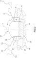
- a loudspeaker according to an embodiment of the present invention is generally indicated with 10 and basically comprises a diaphragm 12, a rigid basket 14, an electric coil 16 (commonly referred to as voice coil and therefore indicated hereinafter with this term), a magnetic circuit 18 and a voice coil support member 20.
- the diaphragm 12 has a conical shape with an upper end (wider end) 12a and a lower end (narrower end) 12b.
- the axis of symmetry of the diaphragm 12, which is indicated z, defines the direction of propagation of the sound waves generated by the loudspeaker 10.
- the loudspeaker 10 is always shown with the axis of symmetry z extending vertically, and terms such as "upper” or "lower” are used with reference to this particular orientation of the loudspeaker.
- the loudspeaker 10 may be used with any orientation, and therefore the axis of symmetry z may extend in any direction other than the vertical one, even in the horizontal direction.
- the voice coil support member 20 is connected to the lower end 12b of the diaphragm 12 and supports the voice coil 16, so that the voice coil support member 20 and the voice coil 16 are movable as a single piece with respect to the magnetic circuit 18 and the basket 14.
- the diaphragm 12, the voice coil 16 and the voice coil support member 20 form a suspended (or movable) part of the loudspeaker 10, while the basket 14 and the magnetic circuit 18 form a non-suspended (or stationary) part of the loudspeaker 10.
- the suspended part and the non-suspended part of the loudspeaker 10 are connected to each other via a first flexible suspension member 22 and a second flexible suspension member 24, which suspension members are configured in such a manner as to constrain the voice coil 16, carried by the voice coil support member 20, to move axially (i.e., parallel to the axis of symmetry z) through a cylindrical air gap 26 of the magnetic circuit 16.
- the first and second flexible suspension members 22 and 24 may be made of any suitable material, for example fabric, rubber or foam.
- the first flexible suspension member 22 connects the upper end 12a of the diaphragm 12 with the basket 14, in particular with an upper portion 14a thereof.
- the second flexible suspension member 24 it is not connected at its inner edge to the voice coil support member 20, as it is the case with the prior art discussed in the introductory part of the present description, but to an annular mounting member 28 which is arranged around the voice coil support member 20 (and has, therefore, a diameter larger than that of the voice coil support member 20) and is attached at its upper end to the diaphragm 12.
- the second flexible suspension member 24 is thus connected at its inner edge to the mounting member 28, in particular to a lower end thereof, and at its outer edge to the basket 14, in particular to a lower portion 14b thereof.
- the mounting member 28 may be made for example of aluminium or polymeric material, such as polyimide.
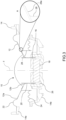
- the mounting member 28 is made as a separate piece with respect to the diaphragm 12.
- the mounting member 28 is a separate piece not only with respect to the diaphragm 12, but also with respect to the second flexible suspension member 24.
- the mounting member 28 is thus attached both to the diaphragm 12 and to the second flexible suspension member 24 using suitable means, for example by gluing.
- the mounting member 28 has at its top a crenelated structure, thereby forming a plurality of protrusions 30, spaced apart from each other, configured to be inserted into corresponding slits 32 provided in the diaphragm 12 so as to ensure better positioning and connection of the mounting member 28 and the diaphragm 12.
- the mounting member 28 has a plurality of inclined upper tabs 28a (better shown in the detail A), each of which is arranged between a respective pair of adjacent protrusions (not shown in Figure 3 , but similar to the protrusions 30 of Figures 1 and 2 ) of the mounting member 28 and extends parallel to the diaphragm 12. This allows to enlarge the adhesion area between the mounting member 28 and the diaphragm 12 and thus strengthen the connection between these two components.
- the upper tabs 28a are shown in Figure 3 as extending outwards, i.e., as facing the upper or wider end 12a of the diaphragm 12, but might also be configured so as to extend inwards, i.e., facing the lower or narrower end 12b of the diaphragm 12.
- FIG 4 shows another embodiment of the present invention, in which the mounting member 28 is formed in one piece with the second flexible suspension member 24. Also in this case, as in the embodiment of Figure 3 , the mounting member 28 has a plurality of inclined upper tabs 28a, each interposed between a respective pair of adjacent protrusions (not shown in Figure 4 , but similar to the protrusions 30 of Figures 1 and 2 ) of the mounting member 28. In this embodiment the inclined upped tabs 28a extend inwards, i.e., towards the lower or narrower end 12b of the diaphragm 12.
- Figure 5 shows another embodiment of the present invention, which is similar to the embodiment of Figure 4 , in that the mounting member 28 is still formed in one piece with the second flexible suspension member 24 and has a plurality of inclined upper tabs 28a extending inwards, i.e., towards the lower or narrower end 12b of the diaphragm 12, and each interposed between a respective pair of adjacent protrusions (not shown in Figure 4 , but similar to the protrusions 30 of Figures 1 and 2 ) of the mounting member 28.
- the difference between the embodiment of Figure 4 and the one of Figure 5 is that in this latter the mounting member 28 is attached with its inclined upper tabs 28a not only to the diaphragm 12 but also to the voice coil support member 20.
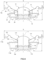
- Figure 6 shows the loudspeaker 10 of Figures 1 and 2 compared to a loudspeaker 110 according to the prior art.
- parts and elements of the loudspeaker 110 of the prior art identical or corresponding to those of the loudspeaker 10 of the invention are indicated with the same reference numerals, increased by 100.
- the two loudspeakers 10 and 110 have the same basket (and hence the same nominal diameter D), the same diaphragm, the same magnetic circuit, the same vertical distance d between the outer edge of the first flexible suspension member and the outer edge of the second flexible suspension member, as well as the same maximum travel t MAX of the voice coil (which in the loudspeaker 10 corresponds to the vertical distance between the lower end 12b of the diaphragm 12 and the upper end of the magnetic circuit 18, while in the loudspeaker 110 corresponds to the vertical distance between the lower end of the second flexible suspension member 124 and the upper end of the magnetic circuit 118).
- the loudspeaker 10 i.e., the loudspeaker of the invention
- the loudspeaker 10 has a voice coil support member 20 with reduced height compared to the voice coil support member 120 of the loudspeaker 110 of the prior art. This allows to reduce the overall height of the loudspeaker (indicated with H for the loudspeaker of the prior art and with h for the loudspeaker of the invention), and hence to obtain a loudspeaker which is more compact in the axial direction (i.e., in the direction of propagation of the sound waves generated by the loudspeaker).
Landscapes
- Engineering & Computer Science (AREA)
- Physics & Mathematics (AREA)
- Acoustics & Sound (AREA)
- Signal Processing (AREA)
- Manufacturing & Machinery (AREA)
- Audible-Bandwidth Dynamoelectric Transducers Other Than Pickups (AREA)
Applications Claiming Priority (1)
| Application Number | Priority Date | Filing Date | Title |
|---|---|---|---|
| IT202300020403 | 2023-10-03 |
Publications (1)
| Publication Number | Publication Date |
|---|---|
| EP4535825A1 true EP4535825A1 (de) | 2025-04-09 |
Family
ID=89068542
Family Applications (1)
| Application Number | Title | Priority Date | Filing Date |
|---|---|---|---|
| EP24197342.9A Pending EP4535825A1 (de) | 2023-10-03 | 2024-08-29 | Lautsprecher mit verringerter höhe |
Country Status (1)
| Country | Link |
|---|---|
| EP (1) | EP4535825A1 (de) |
Citations (6)
| Publication number | Priority date | Publication date | Assignee | Title |
|---|---|---|---|---|
| EP0912072A1 (de) * | 1997-10-27 | 1999-04-28 | Lucio Proni | Aufhängunsgssystem aus konzentrischen Rohren für Lautsprecher |
| WO2005015950A1 (en) | 2003-08-08 | 2005-02-17 | Koninklijke Philips Electronics N.V. | Loudspeaker with undulated membrane |
| US20060177091A1 (en) * | 2004-03-08 | 2006-08-10 | Osamu Funahashi | Speaker and method of manufacturing the same |
| US20070121995A1 (en) | 2004-12-14 | 2007-05-31 | Osamu Funahashi | Speaker |
| FR3024630A1 (fr) | 2014-07-30 | 2016-02-05 | Focal Jmlab | Haut-parleur compact incluant une membrane comprenant des plis radiaux |
| US10820111B2 (en) | 2015-12-14 | 2020-10-27 | Focal Jmlab | Acoustic membrane for a loudspeaker and corresponding loudspeaker |
-
2024
- 2024-08-29 EP EP24197342.9A patent/EP4535825A1/de active Pending
Patent Citations (6)
| Publication number | Priority date | Publication date | Assignee | Title |
|---|---|---|---|---|
| EP0912072A1 (de) * | 1997-10-27 | 1999-04-28 | Lucio Proni | Aufhängunsgssystem aus konzentrischen Rohren für Lautsprecher |
| WO2005015950A1 (en) | 2003-08-08 | 2005-02-17 | Koninklijke Philips Electronics N.V. | Loudspeaker with undulated membrane |
| US20060177091A1 (en) * | 2004-03-08 | 2006-08-10 | Osamu Funahashi | Speaker and method of manufacturing the same |
| US20070121995A1 (en) | 2004-12-14 | 2007-05-31 | Osamu Funahashi | Speaker |
| FR3024630A1 (fr) | 2014-07-30 | 2016-02-05 | Focal Jmlab | Haut-parleur compact incluant une membrane comprenant des plis radiaux |
| US10820111B2 (en) | 2015-12-14 | 2020-10-27 | Focal Jmlab | Acoustic membrane for a loudspeaker and corresponding loudspeaker |
Similar Documents
| Publication | Publication Date | Title |
|---|---|---|
| US7599511B2 (en) | Loudspeaker with undulated membrane | |
| EP2512155B1 (de) | Flacher Lautsprecherwandler | |
| US10299035B2 (en) | Acoustic lens system for loudspeakers | |
| EP0843949A1 (de) | Elektrodynamischer lautsprecher und system mit diesem lautsprecher | |
| US9538291B2 (en) | Speaker | |
| EP3383060A1 (de) | Lautsprechervorrichtung | |
| KR101139126B1 (ko) | 합성 진동판 구조를 가진 라우드스피커 | |
| EP2512154B1 (de) | Lautsprechermagnet mit einem Kanal | |
| US3649776A (en) | Omnidirectional horn loudspeaker | |
| JPH099390A (ja) | 高周波数スピーカ | |
| WO2010010225A1 (en) | Nested compound loudspeaker drive unit | |
| US20230188898A1 (en) | Loudspeaker | |
| US20180317014A1 (en) | Rear suspension for speaker drivers | |
| CN115769600B (zh) | 电声换能器 | |
| EP0954199B1 (de) | Lautsprecher | |
| JPH09284886A (ja) | スピーカ | |
| CN111010656A (zh) | 包括格架的电动扬声器 | |
| JP7437002B2 (ja) | 音響パネルアセンブリ | |
| EP1737269B1 (de) | Flacher Lautsprecher | |
| JPH1042392A (ja) | スピーカ | |
| KR102754313B1 (ko) | 진동 안정성을 향상시킨 스피커 | |
| CN101138271A (zh) | 具有可移动的锥形主体的扬声器 | |
| JP2008118331A (ja) | スピーカ | |
| JP2010114734A (ja) | スピーカ | |
| JP2006129278A (ja) | スピーカユニット |
Legal Events
| Date | Code | Title | Description |
|---|---|---|---|
| PUAI | Public reference made under article 153(3) epc to a published international application that has entered the european phase |
Free format text: ORIGINAL CODE: 0009012 |
|
| STAA | Information on the status of an ep patent application or granted ep patent |
Free format text: STATUS: THE APPLICATION HAS BEEN PUBLISHED |
|
| AK | Designated contracting states |
Kind code of ref document: A1 Designated state(s): AL AT BE BG CH CY CZ DE DK EE ES FI FR GB GR HR HU IE IS IT LI LT LU LV MC ME MK MT NL NO PL PT RO RS SE SI SK SM TR |
|
| STAA | Information on the status of an ep patent application or granted ep patent |
Free format text: STATUS: REQUEST FOR EXAMINATION WAS MADE |
|
| 17P | Request for examination filed |
Effective date: 20250930 |
|
| GRAP | Despatch of communication of intention to grant a patent |
Free format text: ORIGINAL CODE: EPIDOSNIGR1 |
|
| STAA | Information on the status of an ep patent application or granted ep patent |
Free format text: STATUS: GRANT OF PATENT IS INTENDED |
|
| RIC1 | Information provided on ipc code assigned before grant |
Ipc: H04R 9/04 20060101AFI20260123BHEP Ipc: H04R 31/00 20060101ALI20260123BHEP |
|
| INTG | Intention to grant announced |
Effective date: 20260206 |