EP4537652A1 - Courroie transporteuse à entraîneur latéralement stable - Google Patents
Courroie transporteuse à entraîneur latéralement stable Download PDFInfo
- Publication number
- EP4537652A1 EP4537652A1 EP24205750.3A EP24205750A EP4537652A1 EP 4537652 A1 EP4537652 A1 EP 4537652A1 EP 24205750 A EP24205750 A EP 24205750A EP 4537652 A1 EP4537652 A1 EP 4537652A1
- Authority
- EP
- European Patent Office
- Prior art keywords
- conveyor belt
- endless conveyor
- flights
- cross
- endless
- Prior art date
- Legal status (The legal status is an assumption and is not a legal conclusion. Google has not performed a legal analysis and makes no representation as to the accuracy of the status listed.)
- Pending
Links
Images


Classifications
-
- A—HUMAN NECESSITIES
- A01—AGRICULTURE; FORESTRY; ANIMAL HUSBANDRY; HUNTING; TRAPPING; FISHING
- A01D—HARVESTING; MOWING
- A01D61/00—Elevators or conveyors for binders or combines
- A01D61/02—Endless belts
-
- B—PERFORMING OPERATIONS; TRANSPORTING
- B29—WORKING OF PLASTICS; WORKING OF SUBSTANCES IN A PLASTIC STATE IN GENERAL
- B29D—PRODUCING PARTICULAR ARTICLES FROM PLASTICS OR FROM SUBSTANCES IN A PLASTIC STATE
- B29D29/00—Producing belts or bands
- B29D29/06—Conveyor belts
-
- B—PERFORMING OPERATIONS; TRANSPORTING
- B65—CONVEYING; PACKING; STORING; HANDLING THIN OR FILAMENTARY MATERIAL
- B65G—TRANSPORT OR STORAGE DEVICES, e.g. CONVEYORS FOR LOADING OR TIPPING, SHOP CONVEYOR SYSTEMS OR PNEUMATIC TUBE CONVEYORS
- B65G15/00—Conveyors having endless load-conveying surfaces, i.e. belts and like continuous members, to which tractive effort is transmitted by means other than endless driving elements of similar configuration
- B65G15/30—Belts or like endless load-carriers
- B65G15/32—Belts or like endless load-carriers made of rubber or plastics
- B65G15/42—Belts or like endless load-carriers made of rubber or plastics having ribs, ridges, or other surface projections
-
- A—HUMAN NECESSITIES
- A01—AGRICULTURE; FORESTRY; ANIMAL HUSBANDRY; HUNTING; TRAPPING; FISHING
- A01D—HARVESTING; MOWING
- A01D61/00—Elevators or conveyors for binders or combines
- A01D61/008—Elevators or conveyors for binders or combines for longitudinal conveying, especially for combines
Definitions
- the present invention relates to a conveyor belt having the features of the preamble of claim 1, a use of the conveyor belt, a conveyor, and a method for producing an endless conveyor belt.
- Conveyor belts with flighting elements arranged on the surface are well known in practice. There are various applications in which the conveyor belts must have a high degree of transverse stability. In agriculture, for example, such transversely stable conveyor belts are used to convey crops. In particular, such conveyor belts can be used in transverse conveyor devices, such as belt rakes. Belt rakes pick up the crop via a pickup device, called a device. These are equipped with tines or rakes and run between receiving surfaces in a plane parallel to the direction of travel. In doing so, they pick up the crop from the ground and feed it to the transverse conveyor belts.
- a pickup device called a device.
- Transverse conveyor devices By means of the transverse conveyor device, the crop is then conveyed sideways to the direction of travel and deposited back on the ground as a swath or similar.
- Transverse conveyor devices are also used in mowers with a mower to convey the mown crop, such as in draper headers.
- transversely stable conveyor belts for example with a Z-shape, which enable conveying with larger gradients.
- Another area of application for particularly transversely stable conveyor belts is trough belt blasting systems, in which the conveyor belt circulates Workpieces are processed in a blasting process for descaling, derusting and deburring.
- conveyor belts made of cross-linked polymers, particularly rubber, with multiple embedded fabric layers are used. It is common practice to manufacture the flight members attached to the conveyor belt from an elastic material. The flight members must be strong enough to withstand the material being transported while not hindering the conveyor belt's rotation around the rollers.
- an endless conveyor belt made of cross-linked polymer has a plurality of flights that are attached, in particular vulcanized or glued, to a supporting side of the endless conveyor belt, wherein the flights have a height that lies in a range between 10 mm and 60 mm, in particular between 10 mm and 40 mm. Preferably, all flights have the same height.
- the flights are made of cross-linked polymer with at least one embedded fabric layer. The flights are therefore particularly transversely stable. Due to the transverse stability of the flights, the endless conveyor belt can be designed much more simply and yet still has the required transverse stability as a whole.
- the endless conveyor belt has a maximum of three embedded fabric layers.
- the carriers are formed from a folded conveyor belt section, wherein the conveyor belt section is formed from cross-linked polymer with a rubber cover layer and at least one, preferably at least two embedded fabric layers, wherein in two foot regions of the carrier, the conveyor belt section is in a single layer.
- the single-layer feature refers to the conveyor belt section and not to the number of fabric layers in the conveyor belt section.
- a rubber cover layer of the conveyor belt section which is located on the inside of the folded double-layer conveyor belt section, is removed. This allows the endless conveyor belt to rotate smoothly even around relatively small-radius deflection rollers.
- the carriers are formed by means of an extruder.
- the outer layer of the carriers, and thus also the upper edge can be formed from a fabric layer, allowing the carrier to function as a sliding element.
- the fabric layer(s) used in the carriers comprise a monofilament in the transverse direction.
- the endless conveyor belt preferably comprises rubber and the maximum three fabric layers are preferably an EP fabric, wherein it is particularly favorable that the fabric layers are formed from multifilaments.
- the endless conveyor belt has a single fabric layer and is therefore particularly simple in construction.
- a conveyor with a previously described endless conveyor belt wherein preferably the carriers are arranged substantially transversely to the longitudinal direction of the endless conveyor belt and are evenly spaced in the longitudinal direction of the endless conveyor belt, and wherein the endless conveyor belt circulates over deflection rollers and a distance between two consecutive carriers is smaller than the longitudinal extent of a removal area of deflection rollers or in the case of support-side guidance, for example In a bend conveyor, the distance is smaller than the distance between the cleats arranged on the support side, so that it is ensured that a carrier is always located in the area of the cleats during conveying and the conveyor belt is therefore particularly dimensionally stable.
- the steps are preferably performed in the order listed.
- the conveyor belt section is vulcanized on the inside during folding.
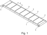
- Figure 1 shows an endless conveyor belt 1 with flights 3 arranged on the supporting side 2.
- the flights 3 extend continuously across almost the entire width of the endless conveyor belt 1 and are arranged at equal spacing along the running direction of the conveyor belt 1.
- the flights 3 are aligned with their longitudinal axes transverse to the running direction of the endless conveyor belt 1.
- the flights 3 are vulcanized onto the upper side of the endless conveyor belt 1. The attachment of the flights 1 by vulcanization makes it impossible for them to detach from the conveyor belt, particularly when the belt is deflected, since no harmful tensile stresses occur due to the elasticity of the material.
- the endless conveyor belt 1 runs on deflection rollers 4.
- the distance a between the flights 3 is selected such that a contact surface on the deflection rollers or the removal area b of the deflection rollers is larger than the distance a between the flights 3. This ensures that at least two consecutive flights 3 are always located within the removal area b.
- the endless conveyor belt 1 is a conveyor belt made of cross-linked polymer, in particular rubber, with at least one embedded fabric layer.
- the conveyor belt 1 must exhibit good transverse stability. This transverse stability can be achieved, for example, by constructing the conveyor belt 1 in multiple layers with several fabric layers.
- Such conveyor belts are expensive to manufacture due to their complex structure. Therefore, according to the invention, particularly transversely stable flights 3 are used, whereby the conveyor belt 1 itself can exhibit lower transverse stability than conventionally required.
- a flight member 3 is shown.
- the flight member 3 is formed from a conveyor belt section made of cross-linked polymer, in particular rubber, with at least one fabric layer.
- the conveyor belt section is folded centrally around the longitudinal axis 100, so that a region 5 with two superimposed layers is formed, in which the conveyor belt section lies twice. Adjacent to this region 5, a foot section 6 of the flight member 3 is formed on both sides.
- the two foot sections 6 lie in a common plane, which extends approximately perpendicular to the double-layered region 5.
- the double-layered region 5 thus forms an elevation that acts as an impact surface when the conveyor belt is in use.
- the conveyor belt section has a rubber cover layer 7 and two schematically illustrated fabric layers 8, 9, wherein the fabric layer 9 remote from the rubber cover layer 7 closes off the conveyor belt section to the outside and is not covered by a second rubber cover layer.
- the rubber cover layer 7 is located on the inside when folded. To simplify folding and to ensure high flexibility when the conveyor belt rotates over the deflection pulley, the rubber cover layer 7 was removed in the two foot regions 6 and at the transition to the double-layer region 5. It is also conceivable to remove or weaken the rubber cover layer only in the bending region (transition between the respective foot region and the double-layer region). In the two foot regions 6, the flight member 3 thus has an embedded fabric layer 8, 9 on the outside and a rubber layer in between.
- the formed flight 3 has a total of four fabric layers 8, 9 in the raised area, which extend in the longitudinal direction of the flight 3 and are approximately parallel to each other in a large part of the double-layered area and approximately perpendicular to the carrying side of the conveyor belt.
- the fold rounds the raised portion of the flight. It is also possible that the fold is flattened when the two layers are joined by vulcanization after folding.
- the conveyor belt section used to manufacture the flight member does not have to be a section of the endless conveyor belt to which the flight member is vulcanized. In other words, the construction can be different.
- the endless conveyor belt preferably has at least two fabric layers, with an inner fabric layer preferably formed from monofilaments.
- the fabric layers are EP fabrics with polyester in the longitudinal direction and polyamide in the transverse direction.
- other fabrics are also conceivable, with a monofilament being preferred in the transverse direction.
- the conveyor belt can be provided with a slit protection system.
- a steel cable cross reinforcement can be incorporated into the rubber cover layer on the load-bearing side, which significantly impedes the penetration of foreign bodies and sharp-edged objects into the strength member of the conveyor belt.
- the steel cable cross reinforcement also called a steel breaker
- the conveyor belt preferably has a maximum of three fabric layers, preferably a single fabric layer. This makes the conveyor belt's structure less complex and significantly more cost-effective to manufacture.
- the conveyor belt section that forms the flight is preferably made of a maximum of five fabric layers.
- the height of the flight is preferably in a range between 10 mm and 60 mm. The height is the distance between the carrying side of the conveyor belt and an upper edge of the flight.
- the conveyor belts have a width of between 0.2 and 2.5 m.
- the drivers can, as in Figure 1 shown, be formed continuously across the belt width. However, it is also conceivable that the flights are divided across the width of the conveyor belt. In this case, the flights preferably have an overlap in the transverse direction. The flights preferably have a constant height across the conveyor belt width. However, it is also It is conceivable that the drivers have recesses or the like in the area of the elevation and that the height of the drivers varies.
- the carriers are preferably designed as described above.
- the at least one fabric layer can be placed in a mold, and a cross-linked polymer, in particular rubber, can be molded around the fabric layer.
- the mold is selected such that foot regions are also formed.
- the carriers can be designed such that the outer layer or outer side is formed by a fabric layer, allowing the carrier to function as a sliding element.
Landscapes
- Engineering & Computer Science (AREA)
- Mechanical Engineering (AREA)
- Life Sciences & Earth Sciences (AREA)
- Environmental Sciences (AREA)
- Extrusion Moulding Of Plastics Or The Like (AREA)
Applications Claiming Priority (1)
| Application Number | Priority Date | Filing Date | Title |
|---|---|---|---|
| DE102023127842.8A DE102023127842A1 (de) | 2023-10-12 | 2023-10-12 | Fördergurt mit querstabilem Mitnehmer |
Publications (1)
| Publication Number | Publication Date |
|---|---|
| EP4537652A1 true EP4537652A1 (fr) | 2025-04-16 |
Family
ID=93099918
Family Applications (1)
| Application Number | Title | Priority Date | Filing Date |
|---|---|---|---|
| EP24205750.3A Pending EP4537652A1 (fr) | 2023-10-12 | 2024-10-10 | Courroie transporteuse à entraîneur latéralement stable |
Country Status (2)
| Country | Link |
|---|---|
| EP (1) | EP4537652A1 (fr) |
| DE (1) | DE102023127842A1 (fr) |
Citations (7)
| Publication number | Priority date | Publication date | Assignee | Title |
|---|---|---|---|---|
| GB712901A (en) * | 1951-03-12 | 1954-08-04 | Helge Fabian Rost | Improvements in or relating to endless conveyer belts |
| US2841515A (en) * | 1956-05-18 | 1958-07-01 | Russell Mfg Co | Conveyor belts |
| US2856064A (en) * | 1953-05-29 | 1958-10-14 | Ton Tex Corp | Conveyor flight belt |
| EP0259244B1 (fr) * | 1986-09-04 | 1991-10-23 | The Goodyear Tire & Rubber Company | Convoyeur pour moissonneuse-batteuse |
| EP2140752B1 (fr) * | 2008-06-30 | 2018-08-22 | Deere & Company | Courroie de convoyeur sans interruption |
| WO2018172963A1 (fr) * | 2017-03-21 | 2018-09-27 | Soucy International Inc. | Courroie de convoyeur à toile |
| WO2023028673A1 (fr) * | 2021-09-01 | 2023-03-09 | Gts Do Brasil Ltda. | Tasseau de courroie de transport |
-
2023
- 2023-10-12 DE DE102023127842.8A patent/DE102023127842A1/de active Pending
-
2024
- 2024-10-10 EP EP24205750.3A patent/EP4537652A1/fr active Pending
Patent Citations (7)
| Publication number | Priority date | Publication date | Assignee | Title |
|---|---|---|---|---|
| GB712901A (en) * | 1951-03-12 | 1954-08-04 | Helge Fabian Rost | Improvements in or relating to endless conveyer belts |
| US2856064A (en) * | 1953-05-29 | 1958-10-14 | Ton Tex Corp | Conveyor flight belt |
| US2841515A (en) * | 1956-05-18 | 1958-07-01 | Russell Mfg Co | Conveyor belts |
| EP0259244B1 (fr) * | 1986-09-04 | 1991-10-23 | The Goodyear Tire & Rubber Company | Convoyeur pour moissonneuse-batteuse |
| EP2140752B1 (fr) * | 2008-06-30 | 2018-08-22 | Deere & Company | Courroie de convoyeur sans interruption |
| WO2018172963A1 (fr) * | 2017-03-21 | 2018-09-27 | Soucy International Inc. | Courroie de convoyeur à toile |
| WO2023028673A1 (fr) * | 2021-09-01 | 2023-03-09 | Gts Do Brasil Ltda. | Tasseau de courroie de transport |
Also Published As
| Publication number | Publication date |
|---|---|
| DE102023127842A1 (de) | 2025-04-17 |
Similar Documents
| Publication | Publication Date | Title |
|---|---|---|
| EP2420125B1 (fr) | Dispositif de transport pour machines de récolte de fruits hachés | |
| DE102019213022A1 (de) | Fördersystem | |
| DE102018108877A1 (de) | Siebbandeinheit | |
| EP2298057B1 (fr) | Dispositif de transport et de nettoyage de produits de récolte sous forme de plantes à racines, notamment sous forme de betteraves sucrières, et chargeuse nettoyeuse dotée d'un tel dispositif | |
| EP3673724A1 (fr) | Moyen de traction, de préférence courroie, pour un convoyeur incliné d'une moissonneuse-batteuse | |
| DE19753510A1 (de) | Steilförderer für landwirtschaftliche Erntemaschinen | |
| DE69329659T2 (de) | Gummi-raupenband mit verbindungsglied | |
| EP4537652A1 (fr) | Courroie transporteuse à entraîneur latéralement stable | |
| WO2021004706A1 (fr) | Élément de transport de type bande ou courroie | |
| EP3216529B1 (fr) | Système de tamis à bande pour un véhicule de nettoyage de plage et véhicule de nettoyage de plage | |
| EP1306000B1 (fr) | Procédé pour l'optimisation de la recolte de fourrage de qualité supérieure | |
| DE3636668C2 (fr) | ||
| EP1300062A1 (fr) | Bande transporteuse | |
| DE102007003195A1 (de) | Erntemaschine | |
| DE3923637C2 (fr) | ||
| DE2828641C2 (fr) | ||
| EP3763194B1 (fr) | Convoyeur transversal d'une machine de récolte agricole | |
| EP3153003A1 (fr) | Barre de coupe comprenant une bande centrale et un dispositif auxiliaire destiné à limiter la perte de grains | |
| EP3800983A1 (fr) | Élément de transport de type bande ou courroie | |
| EP3753869A1 (fr) | Bande transporteuse, utilisation, procédé et dispositif d'empilage ou transport de découpe carton | |
| EP0357877B1 (fr) | Arracheuse de pommes de terre poussée | |
| EP4178888B1 (fr) | Dispositif pour séparer et transporter des plantes racines | |
| DE102018222491A1 (de) | Zahnscheibe für ein Antriebssystem eines Schrägförderers eines Mähdreschers | |
| EP0432701B1 (fr) | Bande transporteuse à lattes | |
| CH670608A5 (fr) |
Legal Events
| Date | Code | Title | Description |
|---|---|---|---|
| PUAI | Public reference made under article 153(3) epc to a published international application that has entered the european phase |
Free format text: ORIGINAL CODE: 0009012 |
|
| STAA | Information on the status of an ep patent application or granted ep patent |
Free format text: STATUS: THE APPLICATION HAS BEEN PUBLISHED |
|
| AK | Designated contracting states |
Kind code of ref document: A1 Designated state(s): AL AT BE BG CH CY CZ DE DK EE ES FI FR GB GR HR HU IE IS IT LI LT LU LV MC ME MK MT NL NO PL PT RO RS SE SI SK SM TR |
|
| STAA | Information on the status of an ep patent application or granted ep patent |
Free format text: STATUS: REQUEST FOR EXAMINATION WAS MADE |
|
| 17P | Request for examination filed |
Effective date: 20251013 |
|
| STAA | Information on the status of an ep patent application or granted ep patent |
Free format text: STATUS: EXAMINATION IS IN PROGRESS |
|
| 17Q | First examination report despatched |
Effective date: 20260327 |