EP4537679A1 - Dispositif de chauffage et dispositif de génération d'aérosol le comprenant - Google Patents
Dispositif de chauffage et dispositif de génération d'aérosol le comprenant Download PDFInfo
- Publication number
- EP4537679A1 EP4537679A1 EP23842127.5A EP23842127A EP4537679A1 EP 4537679 A1 EP4537679 A1 EP 4537679A1 EP 23842127 A EP23842127 A EP 23842127A EP 4537679 A1 EP4537679 A1 EP 4537679A1
- Authority
- EP
- European Patent Office
- Prior art keywords
- electrode
- infrared electrothermal
- conductive electrode
- base body
- coating
- Prior art date
- Legal status (The legal status is an assumption and is not a legal conclusion. Google has not performed a legal analysis and makes no representation as to the accuracy of the status listed.)
- Pending
Links
Images




Classifications
-
- A—HUMAN NECESSITIES
- A24—TOBACCO; CIGARS; CIGARETTES; SIMULATED SMOKING DEVICES; SMOKERS' REQUISITES
- A24F—SMOKERS' REQUISITES; MATCH BOXES; SIMULATED SMOKING DEVICES
- A24F40/00—Electrically operated smoking devices; Component parts thereof; Manufacture thereof; Maintenance or testing thereof; Charging means specially adapted therefor
- A24F40/40—Constructional details, e.g. connection of cartridges and battery parts
- A24F40/46—Shape or structure of electric heating means
-
- A—HUMAN NECESSITIES
- A24—TOBACCO; CIGARS; CIGARETTES; SIMULATED SMOKING DEVICES; SMOKERS' REQUISITES
- A24F—SMOKERS' REQUISITES; MATCH BOXES; SIMULATED SMOKING DEVICES
- A24F40/00—Electrically operated smoking devices; Component parts thereof; Manufacture thereof; Maintenance or testing thereof; Charging means specially adapted therefor
- A24F40/10—Devices using liquid inhalable precursors
-
- A—HUMAN NECESSITIES
- A24—TOBACCO; CIGARS; CIGARETTES; SIMULATED SMOKING DEVICES; SMOKERS' REQUISITES
- A24F—SMOKERS' REQUISITES; MATCH BOXES; SIMULATED SMOKING DEVICES
- A24F40/00—Electrically operated smoking devices; Component parts thereof; Manufacture thereof; Maintenance or testing thereof; Charging means specially adapted therefor
- A24F40/20—Devices using solid inhalable precursors
-
- A—HUMAN NECESSITIES
- A24—TOBACCO; CIGARS; CIGARETTES; SIMULATED SMOKING DEVICES; SMOKERS' REQUISITES
- A24F—SMOKERS' REQUISITES; MATCH BOXES; SIMULATED SMOKING DEVICES
- A24F40/00—Electrically operated smoking devices; Component parts thereof; Manufacture thereof; Maintenance or testing thereof; Charging means specially adapted therefor
- A24F40/40—Constructional details, e.g. connection of cartridges and battery parts
-
- A—HUMAN NECESSITIES
- A24—TOBACCO; CIGARS; CIGARETTES; SIMULATED SMOKING DEVICES; SMOKERS' REQUISITES
- A24F—SMOKERS' REQUISITES; MATCH BOXES; SIMULATED SMOKING DEVICES
- A24F40/00—Electrically operated smoking devices; Component parts thereof; Manufacture thereof; Maintenance or testing thereof; Charging means specially adapted therefor
- A24F40/50—Control or monitoring
- A24F40/51—Arrangement of sensors
-
- A—HUMAN NECESSITIES
- A24—TOBACCO; CIGARS; CIGARETTES; SIMULATED SMOKING DEVICES; SMOKERS' REQUISITES
- A24F—SMOKERS' REQUISITES; MATCH BOXES; SIMULATED SMOKING DEVICES
- A24F40/00—Electrically operated smoking devices; Component parts thereof; Manufacture thereof; Maintenance or testing thereof; Charging means specially adapted therefor
- A24F40/50—Control or monitoring
- A24F40/53—Monitoring, e.g. fault detection
-
- A—HUMAN NECESSITIES
- A24—TOBACCO; CIGARS; CIGARETTES; SIMULATED SMOKING DEVICES; SMOKERS' REQUISITES
- A24F—SMOKERS' REQUISITES; MATCH BOXES; SIMULATED SMOKING DEVICES
- A24F40/00—Electrically operated smoking devices; Component parts thereof; Manufacture thereof; Maintenance or testing thereof; Charging means specially adapted therefor
- A24F40/50—Control or monitoring
- A24F40/57—Temperature control
-
- H—ELECTRICITY
- H05—ELECTRIC TECHNIQUES NOT OTHERWISE PROVIDED FOR
- H05B—ELECTRIC HEATING; ELECTRIC LIGHT SOURCES NOT OTHERWISE PROVIDED FOR; CIRCUIT ARRANGEMENTS FOR ELECTRIC LIGHT SOURCES, IN GENERAL
- H05B3/00—Ohmic-resistance heating
- H05B3/02—Details
- H05B3/06—Heater elements structurally combined with coupling elements or holders
-
- H—ELECTRICITY
- H05—ELECTRIC TECHNIQUES NOT OTHERWISE PROVIDED FOR
- H05B—ELECTRIC HEATING; ELECTRIC LIGHT SOURCES NOT OTHERWISE PROVIDED FOR; CIRCUIT ARRANGEMENTS FOR ELECTRIC LIGHT SOURCES, IN GENERAL
- H05B3/00—Ohmic-resistance heating
- H05B3/40—Heating elements having the shape of rods or tubes
-
- H—ELECTRICITY
- H05—ELECTRIC TECHNIQUES NOT OTHERWISE PROVIDED FOR
- H05B—ELECTRIC HEATING; ELECTRIC LIGHT SOURCES NOT OTHERWISE PROVIDED FOR; CIRCUIT ARRANGEMENTS FOR ELECTRIC LIGHT SOURCES, IN GENERAL
- H05B3/00—Ohmic-resistance heating
- H05B3/40—Heating elements having the shape of rods or tubes
- H05B3/42—Heating elements having the shape of rods or tubes non-flexible
- H05B3/46—Heating elements having the shape of rods or tubes non-flexible heating conductor mounted on insulating base
-
- H—ELECTRICITY
- H05—ELECTRIC TECHNIQUES NOT OTHERWISE PROVIDED FOR
- H05B—ELECTRIC HEATING; ELECTRIC LIGHT SOURCES NOT OTHERWISE PROVIDED FOR; CIRCUIT ARRANGEMENTS FOR ELECTRIC LIGHT SOURCES, IN GENERAL
- H05B2203/00—Aspects relating to Ohmic resistive heating covered by group H05B3/00
- H05B2203/013—Heaters using resistive films or coatings
-
- H—ELECTRICITY
- H05—ELECTRIC TECHNIQUES NOT OTHERWISE PROVIDED FOR
- H05B—ELECTRIC HEATING; ELECTRIC LIGHT SOURCES NOT OTHERWISE PROVIDED FOR; CIRCUIT ARRANGEMENTS FOR ELECTRIC LIGHT SOURCES, IN GENERAL
- H05B2203/00—Aspects relating to Ohmic resistive heating covered by group H05B3/00
- H05B2203/016—Heaters using particular connecting means
-
- H—ELECTRICITY
- H05—ELECTRIC TECHNIQUES NOT OTHERWISE PROVIDED FOR
- H05B—ELECTRIC HEATING; ELECTRIC LIGHT SOURCES NOT OTHERWISE PROVIDED FOR; CIRCUIT ARRANGEMENTS FOR ELECTRIC LIGHT SOURCES, IN GENERAL
- H05B2203/00—Aspects relating to Ohmic resistive heating covered by group H05B3/00
- H05B2203/032—Heaters specially adapted for heating by radiation heating
Definitions
- This application relates to the field of electronic atomization technologies, and in particular, to a heater and an aerosol generating device including the heater.
- the far-infrared coating has a large resistance value, leading to long preheating time of the aerosol-forming substrate, affecting inhalation experience of a user.
- a heater including:
- the connecting electrode divides the infrared electrothermal coating into at least two infrared electrothermal sub-coatings connected in series between the first conductive electrode and the second conductive electrode, and the infrared electrothermal sub-coatings connected in series start heating the aerosol-forming substrate simultaneously. In this way, the problem of a large resistance value of a far-infrared coating is avoided, and inhalation experience of a user is improved.
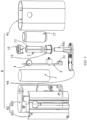
- the housing assembly 6 includes an outer housing 61, a fixing housing 62, a base, and a bottom cover 64, where the fixing housing 62 and the base are fixed in the outer housing 61, the base is configured to fix the heater 11, the base is arranged in the fixing housing 62, and the bottom cover 64 is arranged at an end of the outer housing 61 and covers the outer housing 61.
- An insertion port is provided on the fixing housing 62, and the aerosol-forming substrate is removably received or inserted in the heater 11 through the insertion port.
- the base includes a base 15 sleeved on an upper end of the heater 11 and a base 13 sleeved on a lower end of the heater 11, and the base 15 and the base 13 are arranged in the fixing housing 62.
- An air inlet tube 641 is convexly provided on the bottom cover 64, one end of the base 13 facing away from the base 15 is connected to the air inlet tube 641, the base 15, the heater 11, the base 13, and the air inlet tube 641 are coaxially arranged, the heater 11 is sealed with the base 15 and the base 13 through sealing members, the base 13 and the air inlet tube 641 are also sealed, and the air inlet tube 641 is in communication with external air, so that smooth air intake can be implemented during inhalation by a user.
- the aerosol generating device 100 further includes a circuit board 3 and a battery core 7.
- the fixing housing 62 includes a front housing 621 and a rear housing 622, the front housing 621 is fixedly connected to the rear housing 622, the circuit board 3 and the battery core 7 are arranged in the fixing housing 62, the battery core 7 is electrically connected to the circuit board 3, a key 4 is convexly arranged on the outer housing 61, and the heater 11 can be powered on or off by pressing the key 4.
- the circuit board 3 is further connected to a charging interface 31, the charging interface 31 is exposed on the bottom cover 64, and the user may charge or upgrade the aerosol generating device 100 through the charging interface 31, to ensure continuous use of the aerosol generating device 100.
- the aerosol generating device 100 further includes a temperature sensor 2, for example, an NTC temperature sensor, to detect a real-time temperature of the heater 11, and transmit the detected real-time temperature to the circuit board 3, and the circuit board 3 adjusts a magnitude of a current flowing through the heater 11 according to the real-time temperature.
- a temperature sensor for example, an NTC temperature sensor
- the circuit board 3 controls the battery core 7 to output a high voltage to a conductive element, to further increase a current fed into the heater 11, improve heating power to the aerosol-forming substrate, and reduce time for which the user needs to wait before inhalation is performed.
- the circuit board 3 controls the battery core 7 to output a normal voltage to the heater 11.
- the circuit board 3 controls the battery core 7 to output a low voltage to the heater 11.
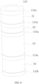
- FIG. 3 and FIG. 4 are a first heater according to an implementation of this application.
- the heater 11 includes: a base body 110, an infrared electrothermal coating 111, and a conductive element.
- the base body 110 may be made of a high-temperature-resistant and transparent material such as silica glass, ceramic, or mica, or may be made of another material with a high infrared ray transmittance, for example, a high-temperature-resistant material with an infrared ray transmittance of 95% or higher. This is not specifically limited herein.
- the base body 110 is approximately in a shape of a tube, and preferably, a shape of a round tube.
- a hollow portion in the base body 110 defines or forms a chamber receiving the aerosol-forming substrate.
- An inner diameter of the base body 110 ranges from 7 mm to 14 mm, or ranges from 7 mm to 12 mm, or ranges from 7 mm to 10 mm.
- the aerosol-forming substrate is a substrate that can release volatile compounds forming aerosols.
- the volatile compounds may be released by heating the aerosol-forming substrate.
- the aerosol-forming substrate may be solid, liquid, or include solid and liquid components.
- the aerosol-forming substrate may be carried on a carrier or a support through absorption, coating, impregnation, or other manners.
- the aerosol-forming substrate may conveniently be a part of an aerosol generating article.
- the aerosol-forming substrate may include nicotine.
- the aerosol-forming substrate may include tobaccos, for example, may include a tobacco-contained material including volatile tobacco-flavor compounds, and the volatile tobacco-flavor compounds are released from the aerosol-forming substrate when the aerosol-forming substrate is heated.
- the aerosol-forming substrate may include at least one aerosol forming agent, and the aerosol forming agent may be any suitable known compound or a mixture of compounds. During use, the compound or the mixture of compounds facilitates formation of dense and stable aerosols and is basically resistant to thermal decomposition under an operating temperature of an aerosol generating system.
- a suitable aerosol forming agent is well known in the art, which includes, but not limited to: polyol, such as triethylene glycol, 1,3-butanediol, and glycerin; polyol ester, such as monoglyceride and diacetate or triacetate; and monobasic carboxylic acid, dibasic carboxylic acid, and polybasic carboxylic acid fatty acid ester, such as dimethyl dodecane dibasic ester and dimethyl tetradecane dibasic ester.
- polyol such as triethylene glycol, 1,3-butanediol, and glycerin
- polyol ester such as monoglyceride and diacetate or triacetate
- monobasic carboxylic acid, dibasic carboxylic acid, and polybasic carboxylic acid fatty acid ester such as dimethyl dodecane dibasic ester and dimethyl tetradecane dibasic ester.
- the infrared electrothermal coating 111 is formed on a surface of the base body 110.
- the infrared electrothermal coating 111 may be formed on an outer surface of the base body 110, or may be formed on an inner surface of the base body 110.
- the infrared electrothermal coating 111 is formed on the outer surface of the base body 110.
- An extension length of the infrared electrothermal coating 111 in an axial direction of the base body 110 ranges from 5 mm to 40 mm; or ranges from 5 mm to 30 mm; or ranges from 5 mm to 20 mm; or ranges from 10 mm to 20 mm.
- the infrared electrothermal coating 111 receives electrical power and generates heat, to radiate an infrared ray having a specific wavelength, for example, a far-infrared ray whose wavelength ranges from 8 ⁇ m to 15 ⁇ m.
- a specific wavelength for example, a far-infrared ray whose wavelength ranges from 8 ⁇ m to 15 ⁇ m.
- the wavelength of the infrared ray is not limited, and the infrared ray may be an infrared ray whose wavelength ranges from 0.75 ⁇ m to 1000 ⁇ m, and preferably, a far-infrared ray whose wavelength ranges from 1.5 ⁇ m to 400 ⁇ m.
- the infrared electrothermal coating 111 is spaced apart from an upper end of the base body 110, and a spacing distance ranges from 0.2 mm to 1 mm, which is conducive to manufacturing and production.
- the infrared electrothermal coating 111 is also spaced apart from a lower end of the base body 110, and a spacing distance ranges from 1 mm to 4 mm, which is conducive to arrangement of a conductive electrode and also prevents a temperature of the lower end of the base body 110 from being excessively high. It should be noted that, viewing from a flow direction of the aerosols, the upper end of the base body 110 is located downstream of the lower end of the base body 110.
- the conductive element includes a conductive electrode 112a, a conductive electrode 112b, a connecting electrode 113a, and a connecting electrode 113b that are arranged at intervals on the surface of the base body 110. That being arranged at intervals refers to that any two of the electrodes are not in direct contact to form a short circuit.
- the conductive electrode 112a includes a coupling portion 112a1 extending in a circumferential direction of the base body 110 and a conductive portion 112a2 extending in an axial direction from the coupling portion 112a1 toward the upper end of the base body 110.
- the conductive portion 112a2 is strip-shaped, and an extension length of the conductive portion in the axial direction is greater than an extension length of the infrared electrothermal coating 111 in the axial direction; and the conductive portion 112a2 remains in contact with the infrared electrothermal coating 111 to form an electrical connection.
- a structure of the conductive electrode 112b is similar to the structure of the conductive electrode 112a, and the conductive electrode 112b and the conductive electrode 112a are symmetrically arranged on the base body 110.
- the conductive portion 112a2 and the conductive portion 112b2 divide the infrared electrothermal coating 111 into a left half part and a right half part.
- the connecting electrode 113a is arranged in the right halt infrared electrothermal coating 111
- the connecting electrode 113b is arranged in the left half infrared electrothermal coating 111.
- the left half infrared electrothermal coating 111 and the right half infrared electrothermal coating 111 are connected in parallel between the conductive portion 112a2 and the conductive portion 112b2.
- the connecting electrode 113a is strip-shaped, and an extension length of the connecting electrode in the axial direction is the same as an extension length of the right half infrared electrothermal coating 111 in the axial direction.
- the connecting electrode 113a divides the right half infrared electrothermal coating 111 into two infrared electrothermal sub-coatings (as shown by A1 and A2 in FIG.
- an equivalent resistance of the infrared electrothermal sub-coating A1 and an equivalent resistance of the infrared electrothermal sub-coating A2 may be the same or may be different.
- an overall resistance of the right half infrared electrothermal coating 111 may be reduced. For example, by arranging one connecting electrode 113a between the conductive portion 112a2 and the conductive portion 112b2, the overall resistance of the right half infrared electrothermal coating 111 may be reduced by about 20%.
- a plurality of connecting electrodes 113a may be arranged in the right half infrared electrothermal coating 111 as required, to divide the right half infrared electrothermal coating 111 into a plurality of infrared electrothermal sub-coatings connected in series between the conductive portion 112a2 and the conductive portion 112b2.
- the connecting electrode 113b is similar to the connecting electrode 113a, and for infrared electrothermal sub-coatings obtained through division, reference may be made to A3 and A4 shown in FIG. 4 .
- the coupling portion 112a1 is electrically connected to a positive electrode of a power supply
- the coupling portion 112b1 is electrically connected to a negative electrode of the power supply (or vice versa)
- a current flows in from the conductive portion 112a2, flows through the infrared electrothermal sub-coating A1 and the infrared electrothermal sub-coating A2 sequentially or flows through the infrared electrothermal sub-coating A3 and the infrared electrothermal sub-coating A4 sequentially, and then flows out from the conductive portion 112b2.
- the connecting electrode 113a and the connecting electrode 113b are not connected to a power supply or a circuit outside the heater 11. That is, the connecting electrode 113a and the connecting electrode 113b are suspended, and the current cannot directly flow in from the connecting electrode 113a and then flow out from the conductive portion 112b2 or the conductive portion 112a2.
- the conductive electrode 112a, the conductive electrode 112b, the connecting electrode 113a, and the connecting electrode 113b are preferably consecutive conductive coatings.
- the conductive coating may be a metal coating, and the metal coating may include silver, gold, palladium, platinum, copper, nickel, molybdenum, tungsten, niobium, or alloy materials of the foregoing metals.
- a width of each of the connecting electrode 113a and the connecting electrode 113b ranges from 0.5 mm to 3 mm; or ranges from 0.5 mm to 2.5 mm. In a specific example, the width may be 1 mm or 2 mm.
- the connecting electrode 113a and/or the connecting electrode 113b may alternatively be non-consecutive conductive coatings, for example, a conductive coating with meshes shown in FIG. 5 .
- the connecting electrode 113a and/or the connecting electrode 113b may be arranged between the base body 110 and the infrared electrothermal coating 111 in a direction perpendicular to the surface of the base body 110; or the infrared electrothermal coating 111 may be arranged between the base body 110 and the connecting electrode.
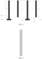
- FIG. 6 shows a second heater according to an implementation of this application.
- an arc-shaped connecting electrode 113a is also feasible.
- FIG. 7 shows a third heater according to an implementation of this application.
- the conductive element includes a conductive electrode 112c arranged at intervals with other conductive electrodes and connecting electrodes.
- the conductive electrode 112a, the conductive electrode 112b, and the conductive electrode 112c divide the infrared electrothermal coating 111 into upper and lower independent heating regions.
- the aerosol-forming substrate may be heated in a segmented manner. For example, the upper half heating region is started first to heat a corresponding upper half part of an article; and the lower half heating region is then started to heat a corresponding lower part of the article. Alternatively, the upper half heating region is started first to heat the corresponding upper half part of the article; and the entire heating region is then started to heat the entire article.
- the connecting electrode 113b is arranged between the conductive electrode 112c and the conductive electrode 112b, and the connecting electrode 113b divides the lower half heating region into two infrared electrothermal sub-coatings (as shown by A3 and A4 in the figure) connected in series between the conductive electrode 112c and the conductive electrode 112b.
- the conductive electrode 112a is electrically connected to a positive electrode of a power supply
- the conductive electrode 112c is electrically connected to a negative electrode of the power supply
- a current flows in from the conductive electrode 112a, flows through the infrared electrothermal sub-coating A1 and the infrared electrothermal sub-coating A2 sequentially, and then flows out from the conductive electrode 112c.
- the conductive electrode 112c is electrically connected to a positive electrode of a power supply
- the conductive electrode 112b is electrically connected to a negative electrode of the power supply
- a current flows in from the conductive electrode 112c, flows through the infrared electrothermal sub-coating A3 and the infrared electrothermal sub-coating A4 sequentially, and flows out from the conductive electrode 112b.
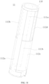
- FIG. 8 shows a fourth heater according to an implementation of this application.
- the conductive electrode 112a and the conductive electrode 112b spirally extend in the axial direction of the base body 110; one connecting electrode 113a is arranged between the conductive electrode 112a and the conductive electrode 112b, the connecting electrode 113a also spirally extends in the axial direction of the base body 110, and a spiral extending height of the connecting electrode is the same as an extension length of the infrared electrothermal coating 111 in the axial direction of the base body 110; and the connecting electrode 113a divides the infrared electrothermal coating 111 into two infrared electrothermal sub-coatings (as shown by A1 and A2 in the figure) connected in series between the conductive electrode 112a and the conductive electrode 112b.
- the conductive electrode 112a is electrically connected to a positive electrode of a power supply
- the conductive electrode 112b is electrically connected to a negative electrode of the power supply
- a current flows in from the conductive electrode 112a, flows through the infrared electrothermal sub-coating A1 and the infrared electrothermal sub-coating A2 sequentially, and then flows out from the conductive electrode 112b.
- adding the conductive electrode 112c to heat the aerosol-forming substrate in a segmented manner in FIG. 7 is also applicable to the heaters in FIG. 3 and FIG. 4 and FIG. 8 . It may be understood that, heating in a plurality of segments may be implemented through a plurality of conductive electrodes.
- the infrared electrothermal coating 111 includes two infrared electrothermal coatings spaced apart from each other, as shown by an infrared electrothermal coating 111a and an infrared electrothermal coating 111b shown in the figure.
- the infrared electrothermal coating 111a is closer to a nozzle end of the aerosol generating device 100 relative to the infrared electrothermal coating 111b.
- a spacing distance between the infrared electrothermal coating 111a and the infrared electrothermal coating 111b ranges from 0.2 mm to 1 mm.
- the conductive electrode 112a includes a coupling portion 112a1 extending in the circumferential direction of the base body 110 and a conductive portion 112a2 extending in the axial direction from the coupling portion 112a1 toward the upper end of the base body 110.
- the coupling portion 112a1 is arc-shaped, the coupling portion 112a1 is spaced apart from the infrared electrothermal coating 111b, and the coupling portion 112a1 is arranged between the infrared electrothermal coating 111b and the lower end of the base body 110; and a wire may be welded on the coupling portion 112a1, to form an electrical connection with a power supply outside the heater 11, for example, the battery core 7 or a voltage converted by the battery core 7, or to form an electrical connection with the power supply through another electrical connector.
- the conductive portion 112a2 is strip-shaped, an extension length of the conductive portion in the axial direction is greater than an extension length of the infrared electrothermal coating 111b in the axial direction, and an upper end of the conductive portion 112a2 is flush with an upper end of the infrared electrothermal coating 111b; and the conductive portion 112a2 remains in contact with the infrared electrothermal coating 111b to form an electrical connection.
- the conductive electrode 112b is strip-shaped, and an extension length of the conductive electrode in the axial direction is the same as an extension length of the infrared electrothermal coating 111a in the axial direction.
- the conductive electrode 112b remains in contact with the infrared electrothermal coating 111a to form an electrical connection.
- a structure of the conductive electrode 112c is similar to that of the conductive electrode 112a.
- a coupling portion 112c1 of the conductive electrode 112c is arranged between the infrared electrothermal coating 111b and the lower end of the base body 110, a conductive portion 112c2 is strip-shaped, but an extension length of the conductive portion in the axial direction is greater than a sum of the extension length of the infrared electrothermal coating 111a in the axial direction and the extension length of the infrared electrothermal coating 111b in the axial direction, and an upper end of the conductive portion 112c2 is flush with an upper end of the infrared electrothermal coating 111a.
- the conductive portion 112c2 remains in contact with the infrared electrothermal coating 111a and the infrared electrothermal coating 111b to form an electrical connection.
- the connecting electrode 113a and the connecting electrode 113b are strip-shaped and are arranged in the infrared electrothermal coating 111b. Extension lengths of the connecting electrode 113a and the connecting electrode 113b in the axial direction are the same as the extension length of the infrared electrothermal coating 111b in the axial direction.
- the connecting electrode 113a is arranged between the conductive electrode 112a and the conductive electrode 112c.
- the connecting electrode 113a divides the infrared electrothermal coating between the conductive electrode 112a and the conductive electrode 112c into two infrared electrothermal sub-coatings (as shown by B1 and B2 in FIG.
- the connecting electrode 113b is also arranged between the conductive electrode 112a and the conductive electrode 112c.
- the connecting electrode 113b divides the infrared electrothermal coating between the conductive electrode 112a and the conductive electrode 112c into two infrared electrothermal sub-coatings (as shown by B3 and B4 in FIG.
- an equivalent resistance of the infrared electrothermal sub-coating B3 and an equivalent resistance of the infrared electrothermal sub-coating B4 may be the same or may be different.
- the infrared electrothermal coating 111a and the infrared electrothermal coating 111b may be independently controlled. Specifically, a power supply may be controlled to provide heating power to the infrared electrothermal coating 111a and/or the infrared electrothermal coating 111b.
- the power supply is first controlled to provide heating power to the infrared electrothermal coating 111a to heat an upper half part (a part corresponding to a region of the infrared electrothermal coating 111a) of an aerosol generating article; and the power supply is then controlled to provide heating power to the infrared electrothermal coating 111b to heat a lower half part (a part corresponding to a region of the infrared electrothermal coating 111b) of the aerosol generating article; or vice versa.
- the power supply is first controlled to provide heating power to the infrared electrothermal coating 111a to heat the upper half part of the aerosol generating article; and the power supply is then controlled to provide heating power to the infrared electrothermal coating 111a and the infrared electrothermal coating 111b simultaneously to heat the entire aerosol generating article.
- the conductive electrode 112b is electrically connected to a positive electrode of the power supply, and the coupling portion 112c1 is electrically connected to a negative electrode of the power supply.
- a current flows in from the conductive electrode 112b, flows through the infrared electrothermal sub-coating A1 or the infrared electrothermal sub-coating A2 in the circumferential direction of the base body 110, and flows out from the conductive portion 112c2.
- the coupling portion 112a1 is electrically connected to the positive electrode of the power supply
- the coupling portion 112c1 is electrically connected to the negative electrode of the power supply
- a current flows in from the conductive portion 112a2
- the connecting electrode 113a and the connecting electrode 113b are not connected to a power supply or a circuit outside the heater 11.
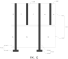
- FIG. 11 and FIG. 12 show a sixth heater according to an implementation of this application.
- an extension length of the conductive portion 112a2 of the conductive electrode 112a in the axial direction is greater than the sum of the extension length of the infrared electrothermal coating 111a in the axial direction and the extension length of the infrared electrothermal coating 111b in the axial direction, and the upper end of the conductive portion 112a2 is flush with the upper end of the infrared electrothermal coating 111a.
- the conductive portion 112a2 remains in contact with the infrared electrothermal coating 111a and the infrared electrothermal coating 111b to form an electrical connection.
- the conductive electrode 112b and a conductive electrode 112d are arranged in the region of the infrared electrothermal coating 111a, and remain in contact with the infrared electrothermal coating 111a to form an electrical connection.
- the conductive electrode 112b, the conductive portion 112a2, the conductive electrode 112d, and the conductive portion 112c2 are arranged at intervals sequentially in the circumferential direction of the base body 110.
- a power supply is first controlled through the conductive electrode 112b and the conductive electrode 112d to provide heating power to the infrared electrothermal coating 111a; and the power supply is then controlled through the conductive electrode 112a and the conductive electrode 112c to provide heating power to the infrared electrothermal coating 111a and the infrared electrothermal coating 111b simultaneously.
- a conductive portion (the conductive portion 112a2 of the conductive electrode 112a and the conductive portion 112c2 of the conductive electrode 112c) between the conductive electrode 112b and the conductive electrode 112d are not powered on, and the conductive portion is equivalent to the connecting electrode in the example of FIG. 9 and FIG. 10 . Therefore, the overall resistance of the infrared electrothermal coating 111a is reduced, so that a temperature of the infrared electrothermal coating 111a is increased rapidly, and the upper half part of the aerosol generating article can be heated rapidly, achieving an objective of producing aerosols rapidly.
- the conductive electrode 112a and the conductive electrode 112c are powered on, the conductive electrode 112b and the conductive electrode 112d between the conductive electrode 112a and the conductive electrode 112c are not powered on, which are also equivalent to the connecting electrode in the example of FIG. 9 and FIG. 10 , so that the overall resistance of the infrared electrothermal coating 111a is reduced.
- the infrared electrothermal coating 111a and the infrared electrothermal coating 111b perform heating simultaneously or the entire infrared electrothermal coating 111 performs heating, due to the existence of the conductive electrode 112b and the conductive electrode 112d, the overall resistance of the infrared electrothermal coating 111a is reduced, so that a temperature in the region of the infrared electrothermal coating 111a is improved, thereby changing a temperature field in the region of the entire infrared electrothermal coating 111.
Landscapes
- Resistance Heating (AREA)
Applications Claiming Priority (2)
| Application Number | Priority Date | Filing Date | Title |
|---|---|---|---|
| CN202210862107.1A CN117461886A (zh) | 2022-07-21 | 2022-07-21 | 加热器以及包括该加热器的气溶胶生成装置 |
| PCT/CN2023/105867 WO2024017062A1 (fr) | 2022-07-21 | 2023-07-05 | Dispositif de chauffage et dispositif de génération d'aérosol le comprenant |
Publications (2)
| Publication Number | Publication Date |
|---|---|
| EP4537679A1 true EP4537679A1 (fr) | 2025-04-16 |
| EP4537679A4 EP4537679A4 (fr) | 2025-11-19 |
Family
ID=89616991
Family Applications (1)
| Application Number | Title | Priority Date | Filing Date |
|---|---|---|---|
| EP23842127.5A Pending EP4537679A4 (fr) | 2022-07-21 | 2023-07-05 | Dispositif de chauffage et dispositif de génération d'aérosol le comprenant |
Country Status (5)
| Country | Link |
|---|---|
| EP (1) | EP4537679A4 (fr) |
| JP (1) | JP2025523699A (fr) |
| KR (1) | KR20250041144A (fr) |
| CN (1) | CN117461886A (fr) |
| WO (1) | WO2024017062A1 (fr) |
Family Cites Families (12)
| Publication number | Priority date | Publication date | Assignee | Title |
|---|---|---|---|---|
| KR20200011723A (ko) * | 2018-07-25 | 2020-02-04 | (주)인터플렉스 | 발열장치 |
| CN110384264A (zh) * | 2019-07-15 | 2019-10-29 | 深圳市合元科技有限公司 | 加热器及低温加热烟具 |
| CN213344347U (zh) * | 2020-07-17 | 2021-06-04 | 深圳市合元科技有限公司 | 加热器以及包括该加热器的烟具 |
| CN114098166A (zh) * | 2020-09-01 | 2022-03-01 | 深圳市合元科技有限公司 | 气溶胶生成装置以及红外加热器 |
| JP2022067751A (ja) * | 2020-10-21 | 2022-05-09 | Future Technology株式会社 | 喫煙カートリッジ用加熱器 |
| CN215958354U (zh) * | 2021-05-12 | 2022-03-08 | 深圳市合元科技有限公司 | 加热器以及包括该加热器的烟具 |
| CN113647691B (zh) * | 2021-07-23 | 2024-08-02 | 深圳麦时科技有限公司 | 加热组件和气溶胶产生装置 |
| CN113633033A (zh) * | 2021-08-25 | 2021-11-12 | 浙江中烟工业有限责任公司 | 加热器及其制备方法以及包含该加热器的气溶胶生成装置 |
| CN216983586U (zh) * | 2021-12-13 | 2022-07-19 | 深圳市合元科技有限公司 | 加热器以及包括该加热器的烟具 |
| CN216875043U (zh) * | 2021-12-31 | 2022-07-05 | 芜湖艾尔达科技有限责任公司 | 加热组件、气溶胶生成装置及流体加热装置 |
| CN114304749B (zh) * | 2021-12-31 | 2024-08-09 | 深圳麦时科技有限公司 | 加热不燃烧气溶胶形成装置及其加热件 |
| CN218354597U (zh) * | 2022-07-21 | 2023-01-24 | 深圳市合元科技有限公司 | 加热器以及包括该加热器的气溶胶生成装置 |
-
2022
- 2022-07-21 CN CN202210862107.1A patent/CN117461886A/zh active Pending
-
2023
- 2023-07-05 EP EP23842127.5A patent/EP4537679A4/fr active Pending
- 2023-07-05 KR KR1020257005621A patent/KR20250041144A/ko active Pending
- 2023-07-05 JP JP2025502453A patent/JP2025523699A/ja active Pending
- 2023-07-05 WO PCT/CN2023/105867 patent/WO2024017062A1/fr not_active Ceased
Also Published As
| Publication number | Publication date |
|---|---|
| JP2025523699A (ja) | 2025-07-23 |
| EP4537679A4 (fr) | 2025-11-19 |
| CN117461886A (zh) | 2024-01-30 |
| WO2024017062A1 (fr) | 2024-01-25 |
| KR20250041144A (ko) | 2025-03-25 |
Similar Documents
| Publication | Publication Date | Title |
|---|---|---|
| EP4209137A1 (fr) | Appareil de génération d'aérosol et dispositif de chauffage infrarouge | |
| KR102865696B1 (ko) | 히터 및 해당 히터를 포함하는 스모킹 세트 | |
| US20220322743A1 (en) | Heater and smoking device including the heater | |
| CN218354597U (zh) | 加热器以及包括该加热器的气溶胶生成装置 | |
| CN211910527U (zh) | 加热器以及包括该加热器的烟具 | |
| US12161163B2 (en) | Heater and cigarette device having same | |
| EP4190184A1 (fr) | Élément chauffant et accessoire de cigarette le contenant | |
| EP4085775A1 (fr) | Élément chauffant et dispositif à fumer comprenant l'élément chauffant | |
| EP4529780A1 (fr) | Ensemble chauffage et appareil de génération d'aérosol | |
| CN113068866B (zh) | 加热器以及包括该加热器的烟具 | |
| EP4241589A1 (fr) | Dispositif de génération d'aérosol | |
| CN219353089U (zh) | 加热器及气溶胶生成装置 | |
| EP4066663A1 (fr) | Atomiseur et cigarette électronique | |
| EP4324348A1 (fr) | Appareil de génération d'aérosol et élément chauffant à infrarouge | |
| CN215347048U (zh) | 气溶胶生成装置以及红外加热器 | |
| JP2025523900A (ja) | エアロゾル発生装置及びその制御方法、並びにエアロゾル発生方法 | |
| EP4537679A1 (fr) | Dispositif de chauffage et dispositif de génération d'aérosol le comprenant | |
| RU2854324C2 (ru) | Устройство для генерации аэрозоля и нагреватель для указанного устройства | |
| CN223614215U (zh) | 加热器以及气溶胶生成装置 | |
| EP4544937A1 (fr) | Ensemble de chauffage et appareil de génération d'aérosol | |
| EP4609736A1 (fr) | Dispositif de chauffage et appareil de génération d'aérosol | |
| EP4613132A1 (fr) | Dispositif de chauffage et son procédé de fabrication, et dispositif de génération d'aérosol | |
| CN121910193A (zh) | 加热器及其制备方法、气溶胶生成装置 |
Legal Events
| Date | Code | Title | Description |
|---|---|---|---|
| STAA | Information on the status of an ep patent application or granted ep patent |
Free format text: STATUS: THE INTERNATIONAL PUBLICATION HAS BEEN MADE |
|
| PUAI | Public reference made under article 153(3) epc to a published international application that has entered the european phase |
Free format text: ORIGINAL CODE: 0009012 |
|
| STAA | Information on the status of an ep patent application or granted ep patent |
Free format text: STATUS: REQUEST FOR EXAMINATION WAS MADE |
|
| 17P | Request for examination filed |
Effective date: 20250107 |
|
| AK | Designated contracting states |
Kind code of ref document: A1 Designated state(s): AL AT BE BG CH CY CZ DE DK EE ES FI FR GB GR HR HU IE IS IT LI LT LU LV MC ME MK MT NL NO PL PT RO RS SE SI SK SM TR |
|
| DAV | Request for validation of the european patent (deleted) | ||
| DAX | Request for extension of the european patent (deleted) | ||
| A4 | Supplementary search report drawn up and despatched |
Effective date: 20251021 |
|
| RIC1 | Information provided on ipc code assigned before grant |
Ipc: A24F 40/10 20200101AFI20251015BHEP Ipc: A24F 40/20 20200101ALI20251015BHEP Ipc: A24F 40/40 20200101ALI20251015BHEP Ipc: A24F 40/46 20200101ALI20251015BHEP Ipc: A24F 40/51 20200101ALI20251015BHEP Ipc: A24F 40/53 20200101ALI20251015BHEP Ipc: A24F 40/57 20200101ALI20251015BHEP Ipc: C09D 5/24 20060101ALI20251015BHEP |