EP4544937A1 - Ensemble de chauffage et appareil de génération d'aérosol - Google Patents
Ensemble de chauffage et appareil de génération d'aérosol Download PDFInfo
- Publication number
- EP4544937A1 EP4544937A1 EP23867273.7A EP23867273A EP4544937A1 EP 4544937 A1 EP4544937 A1 EP 4544937A1 EP 23867273 A EP23867273 A EP 23867273A EP 4544937 A1 EP4544937 A1 EP 4544937A1
- Authority
- EP
- European Patent Office
- Prior art keywords
- electric heating
- film layer
- electrode
- heating film
- matrix
- Prior art date
- Legal status (The legal status is an assumption and is not a legal conclusion. Google has not performed a legal analysis and makes no representation as to the accuracy of the status listed.)
- Pending
Links
Images


Classifications
-
- A—HUMAN NECESSITIES
- A24—TOBACCO; CIGARS; CIGARETTES; SIMULATED SMOKING DEVICES; SMOKERS' REQUISITES
- A24F—SMOKERS' REQUISITES; MATCH BOXES; SIMULATED SMOKING DEVICES
- A24F40/00—Electrically operated smoking devices; Component parts thereof; Manufacture thereof; Maintenance or testing thereof; Charging means specially adapted therefor
- A24F40/40—Constructional details, e.g. connection of cartridges and battery parts
- A24F40/46—Shape or structure of electric heating means
-
- A—HUMAN NECESSITIES
- A24—TOBACCO; CIGARS; CIGARETTES; SIMULATED SMOKING DEVICES; SMOKERS' REQUISITES
- A24F—SMOKERS' REQUISITES; MATCH BOXES; SIMULATED SMOKING DEVICES
- A24F40/00—Electrically operated smoking devices; Component parts thereof; Manufacture thereof; Maintenance or testing thereof; Charging means specially adapted therefor
- A24F40/40—Constructional details, e.g. connection of cartridges and battery parts
-
- A—HUMAN NECESSITIES
- A24—TOBACCO; CIGARS; CIGARETTES; SIMULATED SMOKING DEVICES; SMOKERS' REQUISITES
- A24F—SMOKERS' REQUISITES; MATCH BOXES; SIMULATED SMOKING DEVICES
- A24F40/00—Electrically operated smoking devices; Component parts thereof; Manufacture thereof; Maintenance or testing thereof; Charging means specially adapted therefor
- A24F40/50—Control or monitoring
- A24F40/53—Monitoring, e.g. fault detection
-
- H—ELECTRICITY
- H05—ELECTRIC TECHNIQUES NOT OTHERWISE PROVIDED FOR
- H05B—ELECTRIC HEATING; ELECTRIC LIGHT SOURCES NOT OTHERWISE PROVIDED FOR; CIRCUIT ARRANGEMENTS FOR ELECTRIC LIGHT SOURCES, IN GENERAL
- H05B3/00—Ohmic-resistance heating
- H05B3/0019—Circuit arrangements
-
- H—ELECTRICITY
- H05—ELECTRIC TECHNIQUES NOT OTHERWISE PROVIDED FOR
- H05B—ELECTRIC HEATING; ELECTRIC LIGHT SOURCES NOT OTHERWISE PROVIDED FOR; CIRCUIT ARRANGEMENTS FOR ELECTRIC LIGHT SOURCES, IN GENERAL
- H05B3/00—Ohmic-resistance heating
- H05B3/20—Heating elements having extended surface area substantially in a two-dimensional [2D] plane, e.g. plate-heater
- H05B3/34—Heating elements having extended surface area substantially in a two-dimensional [2D] plane, e.g. plate-heater flexible, e.g. heating nets or webs
-
- H—ELECTRICITY
- H05—ELECTRIC TECHNIQUES NOT OTHERWISE PROVIDED FOR
- H05B—ELECTRIC HEATING; ELECTRIC LIGHT SOURCES NOT OTHERWISE PROVIDED FOR; CIRCUIT ARRANGEMENTS FOR ELECTRIC LIGHT SOURCES, IN GENERAL
- H05B3/00—Ohmic-resistance heating
- H05B3/40—Heating elements having the shape of rods or tubes
- H05B3/42—Heating elements having the shape of rods or tubes non-flexible
- H05B3/46—Heating elements having the shape of rods or tubes non-flexible heating conductor mounted on insulating base
-
- H—ELECTRICITY
- H05—ELECTRIC TECHNIQUES NOT OTHERWISE PROVIDED FOR
- H05B—ELECTRIC HEATING; ELECTRIC LIGHT SOURCES NOT OTHERWISE PROVIDED FOR; CIRCUIT ARRANGEMENTS FOR ELECTRIC LIGHT SOURCES, IN GENERAL
- H05B2203/00—Aspects relating to Ohmic resistive heating covered by group H05B3/00
- H05B2203/013—Heaters using resistive films or coatings
-
- H—ELECTRICITY
- H05—ELECTRIC TECHNIQUES NOT OTHERWISE PROVIDED FOR
- H05B—ELECTRIC HEATING; ELECTRIC LIGHT SOURCES NOT OTHERWISE PROVIDED FOR; CIRCUIT ARRANGEMENTS FOR ELECTRIC LIGHT SOURCES, IN GENERAL
- H05B2203/00—Aspects relating to Ohmic resistive heating covered by group H05B3/00
- H05B2203/032—Heaters specially adapted for heating by radiation heating
-
- H—ELECTRICITY
- H05—ELECTRIC TECHNIQUES NOT OTHERWISE PROVIDED FOR
- H05B—ELECTRIC HEATING; ELECTRIC LIGHT SOURCES NOT OTHERWISE PROVIDED FOR; CIRCUIT ARRANGEMENTS FOR ELECTRIC LIGHT SOURCES, IN GENERAL
- H05B2203/00—Aspects relating to Ohmic resistive heating covered by group H05B3/00
- H05B2203/037—Heaters with zones of different power density
Definitions
- This application relates to the field of electronic atomization technologies, and in particular, to a heating assembly and an aerosol generating apparatus.
- An existing aerosol generating apparatus has the problems of long preheating time for an aerosol-forming substrate and low user experience.
- This application provides a heating assembly and an aerosol generating apparatus, aiming at solving the problems of long preheating time and low user experience that exist in an existing aerosol generating apparatus.
- An aspect of this application provides a heating assembly, including:
- a heating assembly including:
- Another aspect of this application further provides an aerosol generating apparatus, including:
- Another aspect of this application further provides an aerosol generating apparatus, including:
- Another aspect of this application further provides an aerosol generating apparatus, including:
- the electric heating film layers are different in resistance or heating power, so that a temperature of a part of the electric heating film layers can rapidly rise relative to a temperature of another part of the electric heating film layers, so that part of an aerosol-forming substrate can rapidly reach a preheating temperature, a preheating time for the aerosol-forming substrate is shortened, and a vaping waiting time is reduced, thereby improving user experience.
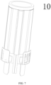
- FIG. 1 and FIG. 2 each show an aerosol generating apparatus 100 according to an implementation of this application, which includes a housing assembly 6 and a heater.
- the heater is arranged in the housing assembly 6.
- the aerosol generating apparatus 100 further includes a circuit 3 and a battery cell 7.
- the fixed housing 62 includes a front housing 621 and a rear housing 622.
- the front housing 621 is fixedly connected to the rear housing 622.
- the circuit 3 and the battery cell 7 are both arranged in the fixed housing 62, and the battery cell 7 is electrically connected to the circuit 3.
- a button 4 protrudes from the housing 61.
- An electric heating film layer on a surface of the matrix 111 such as a resistance heating film layer and an infrared electric heating coating, can be powered on or off by pressing the button 4.
- a charging interface 31 is further connected to the circuit 3, and the charging interface 31 is exposed on the bottom cap 64. The user may charge or upgrade the aerosol generating apparatus 100 through the charging interface 31 to ensure continuous use of the aerosol generating apparatus 100.
- the aerosol generating apparatus 100 further includes a heat insulation tube 17, and the heat insulation tube 17 is arranged in the fixed housing 62.
- the heat insulation tube 17 is arranged on a periphery of the matrix 111.
- the heat insulation tube 17 can prevent a large amount of heat from being transferred to the housing 61, which otherwise causes the user to feel hot.
- the heat insulation tube includes a heat insulation material, and the heat insulation material may be heat insulation glue, an aerogel, aerogel felt, asbestos, aluminum silicate, calcium silicate, diatomaceous earth, zirconia, or the like.
- the heat insulation tube 17 may alternatively be a vacuum heat insulation tube.
- An infrared reflective coating may be further formed in the heat insulation tube 17 to reflect infrared rays emitted by the infrared electric heating coating on the matrix 111 back to the matrix 111, thereby improving heating efficiency.
- the aerosol generating apparatus 100 further includes a temperature sensor 2, such as an NTC thermistor, a PTC thermistor or a thermocouple, for detecting a real-time temperature of the matrix 111 and transmitting the detected real-time temperature to the circuit 3, such that the circuit 3 adjusts a magnitude of a current flowing through the infrared electric heating coating based on the real-time temperature.
- a temperature sensor 2 such as an NTC thermistor, a PTC thermistor or a thermocouple
- FIG. 3 to FIG. 6 each show a heating assembly according to an implementation of this application.
- the heating assembly 10 includes a heater 11, an electrode connection member 12, a temperature sensor 2, and a holding member 14.
- the heater 11 includes: a matrix 111 in which a chamber suitable for containing an aerosol-forming substrate is formed.
- the matrix 111 may be made of a high-temperature resistant and infrared transparent material such as quartz glass, a ceramic or mica, or another material with high infrared transmittance, such as a high-temperature resistant material with infrared transmittance of 95% or above, which is not specifically limited herein.
- a high-temperature resistant and infrared transparent material such as quartz glass, a ceramic or mica, or another material with high infrared transmittance, such as a high-temperature resistant material with infrared transmittance of 95% or above, which is not specifically limited herein.
- the aerosol-forming substrate is a substrate that can release a volatile compound that can form an aerosol.
- the volatile compound may be released by heating the aerosol-forming substrate.
- the aerosol-forming substrate may be a solid or a liquid, or may include solid and liquid components.
- the aerosol-forming substrate may be loaded onto a carrier or a support through adsorption, coating, or impregnation, or in another manner.
- the aerosol-forming substrate may conveniently be a part of an aerosol generating product.
- the aerosol-forming substrate may include nicotine.
- the aerosol-forming substrate may include tobacco, for example, may include a tobacco-containing material including volatile compounds with a tobacco aroma. The volatile compounds with a tobacco aroma are released from the aerosol-forming substrate when the aerosol-forming substrate is heated.
- the aerosol-forming substrate may include a homogeneous tobacco material, such as deciduous tobacco.
- the aerosol-forming substrate may include at least one aerosol-forming agent.
- the aerosol-forming agent may be any suitable known compound or a mixture of compounds. During use, the compound or the mixture of compounds facilitates dense and stable aerosol formation, and is substantially resistant to thermal degradation at an operating temperature of an aerosol-generating system.
- Suitable aerosol-forming agents are well known in this field, including but not limited to: a polyol, such as triethylene glycol, 1,3-butanediol, and glycerol; a polyol ester, such as glycerol monoacetate, glycerol diacetate, or glycerol triacetate; and a fatty acid ester of a monocarboxylic acid, a dicarboxylic acid, or a polycarboxylic acid, such as dimethyl dodecanedioate and dimethyl tetradecanedioate.
- the aerosol-forming agent is polyhydric alcohol or a mixture thereof, such as triethylene glycol, or 1,3-butanediol, and most preferably, glycerol.
- An infrared electric heating coating 112 is formed on a surface of the matrix 111.
- the infrared electric heating coating 112 may be formed on an outer surface of the matrix 111 or an inner surface of the matrix 111.
- the infrared electric heating coating 112 is formed on the outer surface of the matrix 111.
- the infrared electric heating coating 112 receives electric power to generate heat, and then generate infrared rays with a certain wavelength, such as far infrared rays with a wavelength ranging from 8 ⁇ m to 15 ⁇ m.
- a certain wavelength such as far infrared rays with a wavelength ranging from 8 ⁇ m to 15 ⁇ m.
- the infrared electric heating coating 112 is preferably made of far infrared electrothermal ink, ceramic powder and an inorganic binder which are fully and evenly stirred and then coated on the outer surface of the matrix 111, and then dried and cured for a certain period of time.
- the infrared electric heating coating 112 has a thickness ranging from 30 ⁇ m to 50 ⁇ m.
- the infrared electric heating coating 112 may alternatively be made of tin tetrachloride, tin oxide, antimony trichloride, titanium tetrachloride and cupric sulfate anhydrous which are mixed in a certain proportion and then coated on the outer surface of the matrix 111, or is one of a silicon carbide ceramic layer, a carbon fiber composite layer, a zirconium titanium oxide ceramic layer, a zirconium titanium nitride ceramic layer, a zirconium titanium boride ceramic layer, a zirconium titanium carbide ceramic layer, an iron oxide ceramic layer, an iron nitride ceramic layer, an iron boride ceramic layer, an iron carbide ceramic layer, a rare earth oxide ceramic layer, a rare earth nitride ceramic layer, a rare earth boride ceramic layer, a rare earth carbide ceramic layer, a nickel cobalt oxide ceramic layer, a nickel cobalt nitride ceramic layer, a nickel cobalt boride ceramic
- a conductive element includes an electrode 113 and an electrode 114 that are spaced apart on the matrix 111, and is used for feeding electric power provided by the battery cell 7 to the infrared electric heating coating 112.
- the electrode 113 and the electrode 114 remain in contact with the infrared electric heating coating 112 to form an electrical connection.
- the electrode 113 and the electrode 114 may be conductive coatings, and each conductive coating may be a metal coating.
- the metal coating may include silver, gold, palladium, platinum, copper, nickel, molybdenum, tungsten, niobium or an alloy material thereof.
- the electrode 113 and the electrode 114 extend in an axial direction of the matrix 111 and are elongated.
- Axial extension lengths of the electrode 113 and the electrode 114 are the same as an axial extension length of the infrared electric heating coating 112.
- a circumferential extension length or width of each of the electrode 113 and the electrode 114 ranges from 0.2 mm and 5 mm, preferably from 0.2 mm to 4 mm, further preferably from 0.2 mm to 3 mm, further preferably from 0.2 mm to 2 mm, and further preferably from 0.5 mm to 2 mm.
- the electrode 113 and the electrode 114 divide the infrared electric heating coating 112 into two infrared electric heating coatings in a circumferential direction of the matrix 111, namely, a first infrared electric heating coating and a second infrared electric heating coating.
- the two separated infrared electric heating coatings are distributed in the circumferential direction of the matrix 111 and connected in parallel between the electrode 113 and the electrode 114.
- the electrode 113 and the electrode 114 simultaneously feed electric power provided by the battery cell 7 to the first infrared electric heating coating and the second infrared electric heating coating.
- a current may flow from one of the electrodes to the other electrode roughly in a circumferential direction of the matrix 111 through the first infrared electric heating coating.
- the current may also flow from one of the electrodes to the other electrode roughly in another circumferential direction (a direction opposite to the aforementioned circumferential direction.) of the matrix 111 through the second infrared electric heating coating.
- first circumferential distance d1 between the electrode 113 and the electrode 114 in a first circumferential direction of the matrix 111 such as a clockwise direction in FIG. 6 .
- an infrared electric heating coating between the electrode 113 and the electrode 114 is the first infrared electric heating coating.
- second circumferential distance d2 between the electrode 113 and the electrode 114 in a second circumferential direction opposite to the first circumferential direction such as a counterclockwise direction in FIG. 6 .
- an infrared electric heating coating between the electrode 113 and the electrode 114 is the second infrared electric heating coating.
- the first circumferential distance d1 is different from the second circumferential distance d2. If the first infrared electric heating coating has a circumferential extension length of d1 and the second infrared electric heating coating has a circumferential extension length of d2, while an axial extension length of the first infrared electric heating coating is the same as an axial extension length of the second infrared electric heating coating, a flow distance of the current in the first circumferential direction is also different from a flow distance thereof in the second circumferential direction.
- resistance of the first infrared electric heating coating is greater than resistance of the second infrared electric heating coating, that is, the two adjacent infrared electric heating coatings have different resistance in the circumferential direction of the matrix 111.
- heating power of the first infrared electric heating coating is less than heating power of the second infrared electric heating coating, that is, the two adjacent infrared electric heating coatings have different heating power in the circumferential direction of the matrix 111.
- a heating speed of the second infrared electric heating coating is greater than a heating speed of the first infrared electric heating coating.
- the temperature of part of the aerosol-forming substrate corresponding to the second infrared electric heating coating can rise rapidly and an aerosol that can be vaped is generated, thereby shortening a preheating time for the aerosol-forming substrate and reducing a vaping waiting time.
- the heating speed of the second infrared electric heating coating is greater than the heating speed of the first infrared electric heating coating, which can be verified in the following manner:
- the same preset temperature is set, and when the temperature of the second infrared electric heating coating reaches a preset temperature from an initial temperature (such as an ambient temperature), if the temperature of the first infrared electric heating coating is less than the preset temperature, it may indicate that the heating speed of the second infrared electric heating coating is greater than that of the first infrared electric heating coating.
- the preset temperature may be a maximum temperature of the aerosol generating apparatus 100 or an operating temperature, that is, a temperature at which the aerosol-forming substrate can generate an aerosol.
- the above-mentioned preheating stage, thermal insulation stage, or vaping stage are different duration periods in a curve of a temperature change of the aerosol-forming product or infrared electric heating coating with time.
- the first circumferential distance d1 is 1.5-6 times, or twice, or 4 times, or different times as large as the second circumferential distance d2.
- the resistance of one of the infrared electric heating coatings is twice that of the other infrared electric heating coating (assuming the infrared electric heating coating has a uniform thickness).
- the infrared electric heating coating 112 and the proximal end or distal end of the matrix 111 may be spaced apart.
- a portion B1 and a portion B2 on the outer surface of the matrix 111 are provided with no electrode and no infrared electric heating coating 112; and axial extension lengths of the portion B1 and the portion B2 may be as small as possible.
- the axial extension length of each of the portion B1 and the portion B2 ranges from 0 mm to 1 mm, that is, greater than 0 mm and less than or equal to 1 mm, and may be 0.2 mm, 0.4 mm, 0.5 mm, 0.7 mm, or the like in a specific example.
- the infrared electric heating coating 112 and the proximal end or distal end of the matrix 111 are not spaced apart, that is, it is also feasible that the axial extension length of the electrode or infrared electric heating coating 112 is the same as the axial extension length of the matrix 111. In this way, on the one hand, a coating area of the infrared electric heating coating 112 can be increased, and on the other hand, a loss of heat can be avoided.
- the electrode connection member 12 remains in contact with the conductive element to form an electrical connection.
- a quantity of electrode connection members 12 is consistent with a quantity of conductive elements, that is, the electrode 113 has a corresponding electrode connection member 12 and the electrode 114 has a corresponding electrode connection member 12.
- the electrode connection member 12 may be electrically connected to the battery cell 7 through a wire. For example, one end of the wire is welded to the electrode connection member 12, and the other end of the wire is electrically connected to the battery cell 7 (may be electrically connected to the battery cell 7 through a circuit board 3, or may be directly connected to the battery cell 7).
- the electrode connection member 12 is preferably made of copper, a copper alloy, aluminum or an aluminum alloy material with good conductivity, with a surface plated with silver or gold to reduce contact resistance and improve welding performance of the material surface.
- the electrode connection member 12 extends in the axial direction of the matrix 111 and is in the shape of a strip.
- the axial extension length of the electrode connection member 12 and the axial extension length of the conductive element may be the same.
- the circumferential extension length or width of the electrode connection member 12 ranges from 0.2 mm to 5 mm, preferably from 0.2 mm to 4 mm, further preferably from 0.2 mm to 3 mm, further preferably from 0.2 mm to 2 mm, and further preferably from 0.5 mm to 2 mm.
- the thickness of the electrode connection member 12 ranges from 0.05 mm to 1 mm, and may be smaller.
- the thickness of the electrode connection member 12 may be 0.1 mm, 0.2 mm, 0.4 mm, 0.5 mm, or the like.
- the axial extension length of the electrode connection member 12 is greater than the axial extension length of the conductive element, but less than the sum of the axial extension length of the conductive element and the axial extension length of the portion B2.
- the axial extension length of the electrode connection member 12 is greater than the sum of the axial extension length of the conductive element and the axial extension length of the portion B2, that is, an upper end of the electrode connection member 12 is flush with an upper end of the infrared electric heating coating 112, and a lower end of the electrode connection member 12 extends out of the distal end of the matrix 111. This facilitates welding of the wire to the electrode connection member 12.
- a distance between the lower end of the electrode connection member 12 and the distal end of the matrix 111 ranges from 1 mm to 10 mm, preferably from 1 mm to 8 mm, further preferably from 1 mm to 6 mm, and further preferably from 1 mm to 4 mm.
- the outer surface of the matrix 111 has a mark A at a preset position, so that the user can assemble the temperature sensor 2 to the preset position based on the mark A, that is, locate the temperature sensor.
- the mark A can mark a pigment at the preset position by printing or spraying or in another manner.
- the mark A is located between the electrode 113 and the electrode 114 in a direction opposite to the first circumferential direction, that is, a region in which the second infrared electric heating coating is located, or a region in which the infrared electric heating coating with smaller resistance or higher heating power is located.
- the mark A is provided near a central point. In this way, temperature information of the second infrared electric heating coating can be obtained by the temperature sensor 2, so that the circuit 3 can control the battery cell 7 to provide electric power to the first infrared electric heating coating and the second infrared electric heating coating.
- the holding member 14 is used for holding the electrode connection member 12 on the electrode 113 and the electrode 114, and holding the temperature sensor 2 on the mark A.
- the holding member 14 includes a high-temperature adhesive tape or a heat shrinkable tube.
- the high-temperature adhesive tape can be directly wound around the electrode connection member 12 and the temperature sensor 2, or the heat shrinkable tube is sleeved outside the electrode connection member 12 and the temperature sensor 2, and then is shrunk by heating up to fasten the electrode connection member 12 and the temperature sensor 2.
- the electrode connection member 12 is partially exposed outside the holding member 14. This facilitates welding of the wire to the electrode connection member 12.
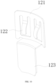
- FIG. 7 to FIG. 10 each show another heating assembly according to another implementation of this application. Different from the examples in FIG. 3 to FIG. 6 ,
- a conductive element further includes an electrode 115 and an electrode 116 that extend in a circumferential direction of the matrix 111.
- the electrode 115 is connected to the electrode 113, and the electrode 116 is connected to the electrode 114.
- the electrode 115 and the electrode 113 may be integrally formed, and the electrode 116 and the electrode 114 may be integrally formed.
- the electrode 115 and the electrode 116 are spaced apart from the infrared electric heating coating 112.
- the portion B2 on the outer surface of the matrix 111 may be wider, and the electrode 115 and the electrode 116 may be both arranged on the portion B2 on the outer surface of the matrix 111, that is, the electrode 115 and the electrode 116 are arranged at the same end of the matrix 111.
- the electrode 115 and the electrode 116 may alternatively be arranged on the portion B1 on the outer surface of the matrix 111, or the electrode 115 and the electrode 116 are arranged at different ends of the matrix 111.
- the electrode connection member 12 includes a contact portion and an extension 123.
- the contact portion includes a body 121 and one or more cantilevers 122 hollowed out on the body 121, and the plurality of cantilevers 122 are distributed in a manner of spacing apart in the circumferential direction of the matrix 111.
- the cantilever 122 can generate an elastic force to achieve an electrical connection with the electrode 115 or the electrode 116.
- the extension 123 extends from the body 121 to a position away from the matrix 111.
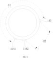
- FIG. 11 shows a heater according to another implementation of this application.
- an electrode 114 includes an electrode 1141 and an electrode 1142.
- the first circumferential distance d1 is different from the second circumferential distance d2.
- the infrared electric heating coating 112 includes a first infrared electric heating coating between the electrode 113 and the electrode 1141, and a second infrared electric heating coating between the electrode 113 and the electrode 1142.
- the resistance of the second infrared electric heating coating is less than the resistance of the first infrared electric heating coating, the heating power of the second infrared electric heating coating is greater than the heating power of the first infrared electric heating coating, and the heating speed of the second infrared electric heating coating is greater than the heating speed of the first infrared electric heating coating.
- three electrodes are taken as an example, and in another example, there may alternatively be four or more electrodes, which can also be implemented.
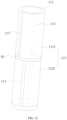
- FIG. 12 shows a heater according to another implementation of this application. Different from the examples in FIG. 3 to FIG. 6 ,
- a portion B3 on the outer surface of the matrix 111 divides the infrared electric heating coating 112 into two independently controllable heating regions, namely, an infrared electric heating coating 1121 and an infrared electric heating coating 1122.
- An axial extension length of the portion B3 may be as small as possible, for example, 0.4 mm to 1 mm, preferably 0.4 mm to 0.8 mm, and further preferably 0.5 mm.
- the electrode further includes an electrode 115 spaced apart on the matrix 111, that is, the electrode 113, the electrode 114 and the electrode 115 are all spaced apart from each other.
- the electrode 115 remains in contact with both the infrared electric heating coating 1121 and the infrared electric heating coating 1122 to form an electrical connection
- the electrode 113 remains in contact with the infrared electric heating coating 1121 to form an electrical connection
- the electrode 114 remains in contact with the infrared electric heating coating 1122 to form an electrical connection.
- the aerosol-forming substrate can be heated segmentally.
- the infrared electric heating coating 1121 is first started for heating (the electrode 113 and the electrode 115 are controlled to be electrified), and then the infrared electric heating coating 1122 is started for heating (the electrode 114 and the electrode 115 are controlled to be electrified), or the infrared electric heating coating 1121 is first started for heating (the electrode 113 and the electrode 115 are controlled to be electrified), and then the infrared electric heating coating 1121 and the infrared electric heating coating 1122 are started for heating together (the electrode 113, the electrode 114 and the electrode 115 are controlled to be electrified together).
- the electrode 113 and the electrode 115 divide the infrared electric heating coating 1121 into two infrared electric heating coatings in the circumferential direction of the matrix 111. Resistance of one of the two infrared electric heating coatings obtained by separation is less than resistance of the other infrared electric heating coating. After the electrode 113 and the electrode 115 conduct electricity, heating power of one of the infrared electric heating coatings is greater than heating power of the other infrared electric heating coating. Therefore, a heating speed of one of the infrared electric heating coatings is greater than a heating speed of the other infrared electric heating coating.
Landscapes
- Resistance Heating (AREA)
Applications Claiming Priority (2)
| Application Number | Priority Date | Filing Date | Title |
|---|---|---|---|
| CN202211160685.7A CN117770526A (zh) | 2022-09-22 | 2022-09-22 | 加热组件以及气溶胶生成装置 |
| PCT/CN2023/116811 WO2024060982A1 (fr) | 2022-09-22 | 2023-09-04 | Ensemble de chauffage et appareil de génération d'aérosol |
Publications (2)
| Publication Number | Publication Date |
|---|---|
| EP4544937A1 true EP4544937A1 (fr) | 2025-04-30 |
| EP4544937A4 EP4544937A4 (fr) | 2026-02-18 |
Family
ID=90378614
Family Applications (1)
| Application Number | Title | Priority Date | Filing Date |
|---|---|---|---|
| EP23867273.7A Pending EP4544937A4 (fr) | 2022-09-22 | 2023-09-04 | Ensemble de chauffage et appareil de génération d'aérosol |
Country Status (5)
| Country | Link |
|---|---|
| EP (1) | EP4544937A4 (fr) |
| JP (1) | JP2025530394A (fr) |
| KR (1) | KR20250065895A (fr) |
| CN (1) | CN117770526A (fr) |
| WO (1) | WO2024060982A1 (fr) |
Family Cites Families (11)
| Publication number | Priority date | Publication date | Assignee | Title |
|---|---|---|---|---|
| KR102318695B1 (ko) * | 2019-12-23 | 2021-10-27 | 주식회사 케이티앤지 | 다중 히터를 구비한 에어로졸 발생 장치 및 그의 제어 방법 |
| CN114052300A (zh) * | 2020-08-03 | 2022-02-18 | 深圳市合元科技有限公司 | 加热器以及含有该加热器的烟具 |
| CN213848764U (zh) * | 2020-08-03 | 2021-08-03 | 深圳市合元科技有限公司 | 加热器以及包括该加热器的烟具 |
| CN114098166A (zh) * | 2020-09-01 | 2022-03-01 | 深圳市合元科技有限公司 | 气溶胶生成装置以及红外加热器 |
| CN216875043U (zh) * | 2021-12-31 | 2022-07-05 | 芜湖艾尔达科技有限责任公司 | 加热组件、气溶胶生成装置及流体加热装置 |
| CN217184817U (zh) * | 2022-01-24 | 2022-08-16 | 深圳市合元科技有限公司 | 加热器、气雾生成装置及气雾生成系统 |
| CN218354597U (zh) * | 2022-07-21 | 2023-01-24 | 深圳市合元科技有限公司 | 加热器以及包括该加热器的气溶胶生成装置 |
| CN219182820U (zh) * | 2022-09-22 | 2023-06-16 | 深圳市合元科技有限公司 | 加热组件以及气溶胶生成装置 |
| CN219182821U (zh) * | 2022-09-23 | 2023-06-16 | 深圳市合元科技有限公司 | 加热组件以及气溶胶生成装置 |
| CN219353089U (zh) * | 2022-12-08 | 2023-07-18 | 深圳市合元科技有限公司 | 加热器及气溶胶生成装置 |
| CN219781579U (zh) * | 2022-12-08 | 2023-10-03 | 深圳市合元科技有限公司 | 加热器及气溶胶生成装置 |
-
2022
- 2022-09-22 CN CN202211160685.7A patent/CN117770526A/zh active Pending
-
2023
- 2023-09-04 JP JP2025515929A patent/JP2025530394A/ja active Pending
- 2023-09-04 KR KR1020257011782A patent/KR20250065895A/ko active Pending
- 2023-09-04 EP EP23867273.7A patent/EP4544937A4/fr active Pending
- 2023-09-04 WO PCT/CN2023/116811 patent/WO2024060982A1/fr not_active Ceased
Also Published As
| Publication number | Publication date |
|---|---|
| EP4544937A4 (fr) | 2026-02-18 |
| WO2024060982A1 (fr) | 2024-03-28 |
| CN117770526A (zh) | 2024-03-29 |
| JP2025530394A (ja) | 2025-09-11 |
| KR20250065895A (ko) | 2025-05-13 |
Similar Documents
| Publication | Publication Date | Title |
|---|---|---|
| EP4209137A1 (fr) | Appareil de génération d'aérosol et dispositif de chauffage infrarouge | |
| US20220322743A1 (en) | Heater and smoking device including the heater | |
| US20220338541A1 (en) | Heater and smoking device including heater | |
| KR102865696B1 (ko) | 히터 및 해당 히터를 포함하는 스모킹 세트 | |
| US12161163B2 (en) | Heater and cigarette device having same | |
| CN211910527U (zh) | 加热器以及包括该加热器的烟具 | |
| EP4190184A1 (fr) | Élément chauffant et accessoire de cigarette le contenant | |
| EP4529780A1 (fr) | Ensemble chauffage et appareil de génération d'aérosol | |
| CN219353089U (zh) | 加热器及气溶胶生成装置 | |
| CN219781579U (zh) | 加热器及气溶胶生成装置 | |
| EP4559331A1 (fr) | Dispositif de génération d'aérosol et son procédé de commande, et procédé de génération d'aérosols | |
| CN219182820U (zh) | 加热组件以及气溶胶生成装置 | |
| CN219182821U (zh) | 加热组件以及气溶胶生成装置 | |
| EP4544937A1 (fr) | Ensemble de chauffage et appareil de génération d'aérosol | |
| EP4613132A1 (fr) | Dispositif de chauffage et son procédé de fabrication, et dispositif de génération d'aérosol | |
| EP4609736A1 (fr) | Dispositif de chauffage et appareil de génération d'aérosol | |
| RU2854324C2 (ru) | Устройство для генерации аэрозоля и нагреватель для указанного устройства | |
| RU2852317C2 (ru) | Нагреватель и устройство для генерирования аэрозоля | |
| CN223614215U (zh) | 加热器以及气溶胶生成装置 | |
| EP4537679A1 (fr) | Dispositif de chauffage et dispositif de génération d'aérosol le comprenant | |
| CN121910193A (zh) | 加热器及其制备方法、气溶胶生成装置 |
Legal Events
| Date | Code | Title | Description |
|---|---|---|---|
| STAA | Information on the status of an ep patent application or granted ep patent |
Free format text: STATUS: THE INTERNATIONAL PUBLICATION HAS BEEN MADE |
|
| PUAI | Public reference made under article 153(3) epc to a published international application that has entered the european phase |
Free format text: ORIGINAL CODE: 0009012 |
|
| STAA | Information on the status of an ep patent application or granted ep patent |
Free format text: STATUS: REQUEST FOR EXAMINATION WAS MADE |
|
| 17P | Request for examination filed |
Effective date: 20250127 |
|
| AK | Designated contracting states |
Kind code of ref document: A1 Designated state(s): AL AT BE BG CH CY CZ DE DK EE ES FI FR GB GR HR HU IE IS IT LI LT LU LV MC ME MK MT NL NO PL PT RO RS SE SI SK SM TR |
|
| DAV | Request for validation of the european patent (deleted) | ||
| DAX | Request for extension of the european patent (deleted) | ||
| A4 | Supplementary search report drawn up and despatched |
Effective date: 20260120 |
|
| RIC1 | Information provided on ipc code assigned before grant |
Ipc: A24F 40/46 20200101AFI20260114BHEP |