EP4537706A1 - Stützvorrichtung, die eine höheneinstellung des gestützten objekts, zum beispiel möbel, ermöglicht - Google Patents
Stützvorrichtung, die eine höheneinstellung des gestützten objekts, zum beispiel möbel, ermöglicht Download PDFInfo
- Publication number
- EP4537706A1 EP4537706A1 EP24203781.0A EP24203781A EP4537706A1 EP 4537706 A1 EP4537706 A1 EP 4537706A1 EP 24203781 A EP24203781 A EP 24203781A EP 4537706 A1 EP4537706 A1 EP 4537706A1
- Authority
- EP
- European Patent Office
- Prior art keywords
- spur
- wheel
- base
- way
- rotation
- Prior art date
- Legal status (The legal status is an assumption and is not a legal conclusion. Google has not performed a legal analysis and makes no representation as to the accuracy of the status listed.)
- Pending
Links
Images


Classifications
-
- A—HUMAN NECESSITIES
- A47—FURNITURE; DOMESTIC ARTICLES OR APPLIANCES; COFFEE MILLS; SPICE MILLS; SUCTION CLEANERS IN GENERAL
- A47B—TABLES; DESKS; OFFICE FURNITURE; CABINETS; DRAWERS; GENERAL DETAILS OF FURNITURE
- A47B91/00—Feet for furniture in general
- A47B91/02—Adjustable feet
- A47B91/022—Adjustable feet using screw means
- A47B91/028—Means for rotational adjustment on a non-rotational foot
Definitions
- the present invention relates to a support device for objects in general, preferably furniture and furnishings (particularly in nautical environment), which device (one or more than one) supports an object thus allowing easy and immediate levelling adjustment on the rest ground.
- the invention relates to this support device 1 which allows lifting and/or lowering the rest base surface of the device itself by means of a simple screw mechanism thereby varying its overall height from the ground.
- the aim of the present invention is to provide a device which solves at least partially said technical inconveniences.
- the aim of the present invention is to provide a levelling device which allows not only supporting an object with respect to the ground but also its levelling adjustment simply and quickly also when the object is already laying on said device.
- This levelling device 1 is adapted to support any object, for example a decor item or furniture in general, and comprises:
- the object lies and is supported by the rest base of one or more of said devices (depending on the size of the object one or more devices may be necessary).
- this pin which can be driven into rotation controls, through its rotation in one direction or in the opposite direction, activation of the gear system of which it is part and which controls translation upwards or downwards of the levelling device as a whole, and therefore integrally, of said support base.
- the operator may easily activate the gear system which causes lifting or lowering of the support base on which the object rests.
- the operator may place a regular level, for example a spirit level, on the object to see whether it is perfectly levelled or not.
- a regular level for example a spirit level
- the operator may act manually independently on each of said objects by rotating, for example by means of suitable tool, the pins of each of them, thereby causing translation upwards or downwards of the support base on which the object rests.
- the overall height of the whole levelling device varies thereby lifting or lowering the supported object.
- the stroke may be in the order of millimeters for example, but it allows lowering and/or lifting all rest points of the object until the levelling tool (for example said spirit or laser level) marks reaching of the desired position.
- levelling tool for example said spirit or laser level
- this levelling device constitutes a real rest base for the object and with the object which is no longer removed from above said devices.
- a wardrobe For example a wardrobe, one may select the adequate number of devices which are laid on the ground and on which the wardrobe is firmly fixed. At that point, if the wardrobe must be levelled, then one proceeds as indicated above.
- said gear system (d1, d2, 4) comprises a first part (3a, 3b) of said gear system which is cooperating with a second part (3c) of this gear system.
- said first part comprises said pin (3a) comprising its said end (3a') activatable into rotation in order to drive the pin into rotation (rotation around its longitudinal axis of the end and obviously of the pin) and with said pin equipped with, on the side opposite to said end (3a'), a helicoidal threading (d2) (therefore helicoidal toothing).
- said second part of the gear system comprises a spur-wheel (3b) (rotatable around its longitudinal axis) meshing with said helicoidal threading (d2) in such a way that rotation of said pin (3a) determines rotation of the spur-wheel (3b) through engagement of the teeth (d1) of said spur-wheel with the helicoidal threading (d2).
- the spur-wheel is placed with its rotation axis (longitudinal axis) orthogonal with respect to the rotation axis (always longitudinal axis) of the pin.
- the spur-wheel (3b) has a threaded axial channel (indeed coincident with the longitudinal axis of the spur-wheel and therefore coincident with the rotation axis).
- this second part of the gear system further comprises a threaded rod (4) which is inserted into said threaded channel of the spur-wheel and meshing with the threading of said axial channel of said spur-wheel.
- rotation of the spur-wheel determines translation of the threaded rod (4) by meshing the threading of the threaded rod (4) with the threading of said axial channel of the spur-wheel.
- the axial channel of the spur-wheel functions as a sliding guide.
- said first part of the gear system and the spur-wheel are arranged inside the frame.
- said threaded rod (4) protrudes from a base (5).
- the frame comprises an upper part (2a) comprising said support base (10, 63) through which said object is supported and a lower part (2b) comprising said rest base (22) to rest on the ground.
- the upper part and the lower part of the frame contains said spur-wheel (3b) and are axially holed to form a passage channel aligned with the channel of the spur-wheel arranged inside.
- said threaded rod (4) can pass through said two parts of the frame passing through the channel of the spur-wheel with which it is meshing through the reciprocal threadings.
- the rotation in one direction or in the opposite direction of the spur-wheel determines a translation of the threaded rod along the channel of the spur-wheel with which the threaded rod is meshing with a consequent moving-away or approaching of said base (5), from which the treaded rod (4) protrudes, with respect to the rest base (22).
- said one or more guide holes (6') may be obtained in the lower part of the frame.
- said base (5) as a function of the movement of the gear system is movable between an extended position in which it extends externally from the rest base (22) thereby determining a lifting of the whole device from the ground on which it rests and a retracted position in which it moves close to the rest base (22) thereby lowering the whole device.
- a seat or recess may be provided in which the base 5 is inserted in a retractable way which is thus flush with the rest base 22 in said retracted position.
- a flanged accessory (60) may be comprised which can be coupled with the support base (10; 63) of the frame and comprising a support surface of flanged type for the object.
- a control rod (70) may be comprised, for example in the form of an accessory which may be used when needed.
- the device may comprise a second pin (3a', 3a) which can rotate freely.
- said second pin may have its two free ends and at least partially accessible and protruding from the frame.
- said control rod (70) can be connected at an end thereof to a free end of said second pin and, at the other end thereof, said control rod (70) can be connected to the end (3a') of a further device placed at a distance.
- the second pin has undercuts (for example with hexagonal shape) to be engaged with the end of the rod 70 (the two ends of the rod 70 may be identical) which provides, like a lug wrench, the cavity conformed to receive said shaped end of the pin.
- control rod Since the control rod is/may be connected to another twin device 1, then this control rod transmits its rotation to the end (3a') of the pin of said further device with which said pin (70) is connected, thus determining a variation of height thereof. Also the connection of the rod 70 with the further end of the pin relative to the further device 1 occurs through conformation of this end of the rod 70 in the form of lug wrench or the like, as described above.
- Another object of the present invention is an assembly which comprises an angle bar (300) comprising at least two tongues (301) which protrude therefrom and adapted to be inserted into a seat of a section bar (100) in such a way that two section bars (100) can be connected to each other in succession through said angle bar which functions as connection.
- the assembly also comprises a device, according to one or more of the previous features described above, and coupled with said angle bar.
- said at least two tongues (301) are placed to form a right angle between each other in such a way that the two section bars can be connected to each other through said angle bar according to a right angle.
- quadrangular or rectangular frames may be created.
- the present invention concerns a device (1) which, with a simple gear mechanism, allows lifting and/or lowering the rest surface of the device itself to the ground, thereby varying its height from the ground (substantially it can be lifted and/or lowered). In this way, levelling of the supported objects can be adjusted.
- figure 1 shows an exploded view to highlight the structural parts of the device 1 object of the invention.
- the device 1 comprises a frame 2 (visible assembled in figure 2 ) which, as shown in the exploded view of figure 1 , may comprise an upper part of frame (2a), a lower part of frame (2b).
- a first part (3a, 3b) of a gear system 3 is housed which cooperates with a second part (3c) of this gear system, as better described below.
- the gear system is responsible for lifting and/or lowering of the described device, in such a way as to lift and/or lower the object or the supported portion of the object.
- the upper part of frame (2a) comprises an upper surface (also called support base) which is the one intended to support the object in use.
- said upper surface may be of circular type given that it is generated by a cylindrical body 11 having a circular edge 10 and with said cylindrical body 11 rising from the base 12.
- the cylindrical shape is not essential and therefore the circular shape of the edge 10 is not necessary.
- this lid could be a simple disc which closes and is applied around the edge 10.
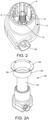
- the channel delimited by the edge 10 may be closed by a further accessory which comprises a flanged tubular body whose tube is inserted by interference into the channel of the cylinder 11.
- the opposite flanged part is protruding outside this channel and has a flange with holes for passage of screws and inserts. This allows firm and good fixing of said device to the object.
- this flanged tubular (which is an accessory) is depicted in figure 2A and comprises a tube 61 adapted to be inserted and locked into the channel of the cylinder 11.
- the upper part of this tube forms a flanged body (62, 63) which ends indeed with a flange 63 equipped with one or more holes for passage of inserts, screws or similar connection systems.
- the object may rest on a good support base constituted by said flange 62 and may be screwed through the holes 64 and passage of said screws or inserts and the like.
- the upper part of frame (2a) is axially hollow and therefore it forms said passage channel which functions as passage of the threaded rod 4 as described below.
- the lower part of the frame (2b) is such that it can be coupled with the upper part to form a sort of box-shaped element.
- the lower part (2b) is in plan form like a circular shape even if other shapes may be easily manufactured.
- the lower part (2b) forms a rest base to the ground 22 while, for the opposite side, it forms a seat 23 which functions as housing for at least part of the first part (3a, 3b) of the gear system which is then extended in a seat which follows its shape. In this way, the seat forms a entry path which facilitates correct assembly of the parts.
- the lower part (2b) forms an axial channel which is obviously aligned with the channel of the upper part (2a) for passage of the threaded rod 4.
- the part (3c) comprises the second part of the gear system which is cooperating with the first part as described below regarding functioning.
- said second part of the gear system comprises a threaded rod 4 with threading which is engaged with a gear of the first part of the gear system.
- this base is flat, for example with the shape of disc or circular.
- This threaded rod 5 (therefore connected integrally with said base 5) rises from this base which base engages and is then cooperating with the first part of the gear system.
- each hole 6' forms a linear sliding guide along which the rod 6 may slide and which allows vertical translation of the whole assembly (3c) with respect to the lower base 22.
- the first part of the gear system it engages with the threaded rod thus causing translation of the whole assembly (3c).
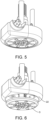
- the whole assembly (3c) can be then translated with respect to the frame thus being able to slide with respect to it thanks to the guides (6') and therefore the base 5 can extend outside of the base 22 relative to the lower part of the frame 2b (as per figure 6 ) and can retract inside it (as per figure 5 ).
- This determines a variation of the overall height of the device with consequent lifting/lowering of the support base (10; 63) on which the object rests.
- the first part (3a, 3b) of the gear system comprises a pin (3a) which ends at an end thereof with an end part (3a') which may have such a conformation as to be easily grasped by a tool to cause its rotation, for example a lug wrench (for example hex wrench) .
- said end part (3a') may be conformed with hexagonal shape or any other type of undercut adapted to allow easy grasping also with tools such as pliers and causing its rotation. Therefore, the end part (3a') is an activation terminal where an operator, with suitable manual or automatic tool, such as a lug wrench or with an automatic machinery similar to the lug wrench, can activate this pin (3a) into rotation.
- the pin (3a) comprises a threading to form a single gear which is coupled with the gear of a sort of spur-wheel (3b).
- the pin (3a) forms a helicoidal screw which is rotationally coupled with a sort of spur-wheel (3b).
- the spur-wheel (3b) is a cylindrical body which provides on the outside these teeth (d1) which are coupled with the teeth (d2) of the screw in such a way that rotation of the screw in one direction or in the opposite direction causes the relative rotation of the spur-wheel (3b) in a relative direction or in the opposite direction.
- the cylindrical body of the spur-wheel (3b), in its turn, is axially holed in a pass-through way as well to allow passage of the threaded rod 4.
- This axial channel is threaded with a threading which engages with the threading relative to the rod 4.
- the spur-wheel is aligned with the two parts of frame and forming an axial channel axially aligned with the one of the two parts of frame, for allowing passage of the threaded rod 4.
- the cylindrical body (3b) has the threaded axial channel which engages with the threading of the rod 4 which rod protrudes from the base 5 and is integral with it. In this way, depending on the direction of rotation of the cylindrical body (3b), translation of the rod 4 is determined, given that the threading of the channel of said cylindrical body is engaged with the threading of the rod 4. In this way, given that the whole block 3c is constrained to slide through the rods 6 and cannot rotate, it follows that rotation of the cylindrical body (3b) constrained in position determines sliding of the rod 4 along the channel of the cylindrical body (3b) which functions, actually, as activation system and guide of said rod 4.
- the spur-wheel from the cylindrical body is indeed locked and packed between the two parts of the frame and therefore cannot translate.
- the unit (3c) may only translate. It follows translation of the threaded rod 4 along the guide formed by the cylindrical body threaded inside (3b) with a consequent movement of the surface 5 as per figures 5 and 6 . If the rod 4 translates downwards, the result will be, as per figure 6 , that the surface 5 protrudes by projecting outside with respect to the base 22 of the lower part of the frame.
- the base 5 retracts towards the base 22 as per figure 5 .
- the lower part of the frame may advantageously form a seat adapted to fully house inside it the base 5 (for example with the shape of disc).
- the object is firmly resting on four of these devices placed at any four angles of said object, at this point the object not only rests firmly but it can easily be levelled with respect to the ground if it is uneven.
- a spirit level may be applied on the object and then one may act on one or more of said devices by adjusting them in an independent way from each other, for example by acting on one or more of them depending on the cases.
- the pin relative to one of them may be rotated in such a way as to cause protrusion of the surface 5 as per figure 6 by a certain desired amount (for example few millimetres), in such a way as to incline the object by this lifting amount.
- the object may be levelled precisely thus also compensating for unevenness of the ground.
- the device may be used as shown in said figures taking care to arrange under the object the necessary number of devices.
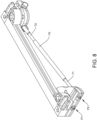
- Figure 7 shows a variant of invention in which the two devices 1 as described are fixed to the ends of a section bar 100 which may be used, by combining it with other section bars, to form a rest plane for objects and with the rest plane that can be adjusted as described above.
- the device 1 may be fixed to an angle bar 300 fitted with tongues 301 placed at right angles between each other in such a way that each tongue can penetrate the relative raceway of the section bar.
- the angle bar 300 can provide at least one tongue protruding from a part thereof (preferably at least two tongues) and, at right angle, at least one other tongue 301 protruding from another side thereof (preferably at least two tongues), in such a way as to assume indeed the shape of angle bar with right angle in which the two ends thereof (i.e. tongues) are made to be inserted by sliding into the two raceways of a section bar.
- Fixing of the section bar to the tongues of the angle bar may occur with screws or inserts in general 200.
- each device may provide two control points (P1) and (P2) and of which the point (P1) corresponds to the end (3a') already described which controls the gear system.
- the second point (P2) is identical to (P1) but it is in the form of a simple pin which therefore is not connected and does not activate any gear. It is merely a rotatable idle pin which is an engagement point (P2) for the rod 70 which is connected, by the end opposite to the end (3a') of the other opposite device (this end is obviously connected to the gear system of said further opposite device).
- a user may control and adjust the device relative to it and through (P2) may adjust the other device given that rotation of P2 is transmitted to the rod 70 and from it to the end (3a') of the other device with which the rod is connected by the opposite end.
- This variant can be applied to the single devices described in figures from 1 to 6 thus providing presence of two pins as just described and the rod 70.
- this variant may also be applied to the device equipped and connected with angle bar (see figure 7 ).
- angle bar as described in figure 7 to which the device described above is connected having the two pins (P1, P2) as per figure 8 .
Landscapes
- Transmission Devices (AREA)
- Legs For Furniture In General (AREA)
Applications Claiming Priority (1)
| Application Number | Priority Date | Filing Date | Title |
|---|---|---|---|
| IT102023000021369A IT202300021369A1 (it) | 2023-10-13 | 2023-10-13 | Un dispositivo di supporto che consente di regolare la livellazione dell’oggetto che sorregge, ad esempio un mobilio |
Publications (1)
| Publication Number | Publication Date |
|---|---|
| EP4537706A1 true EP4537706A1 (de) | 2025-04-16 |
Family
ID=89426900
Family Applications (1)
| Application Number | Title | Priority Date | Filing Date |
|---|---|---|---|
| EP24203781.0A Pending EP4537706A1 (de) | 2023-10-13 | 2024-10-01 | Stützvorrichtung, die eine höheneinstellung des gestützten objekts, zum beispiel möbel, ermöglicht |
Country Status (2)
| Country | Link |
|---|---|
| EP (1) | EP4537706A1 (de) |
| IT (1) | IT202300021369A1 (de) |
Citations (3)
| Publication number | Priority date | Publication date | Assignee | Title |
|---|---|---|---|---|
| DE29512662U1 (de) * | 1995-08-05 | 1996-12-05 | A-Z Ausrüstung und Zubehör GmbH & Co KG, 42579 Heiligenhaus | Höhenverstellbarer Fuß für Küchengeräte oder Möbel |
| EP1103206A1 (de) * | 1999-11-26 | 2001-05-30 | Esswein S.A. | Höhenverstellbares Fussystem für Möbelausrüstung und Verfahren zu dessen Montage |
| WO2014177227A1 (en) * | 2013-05-03 | 2014-11-06 | Arcelik Anonim Sirketi | Household appliance having improved height profile adjustable feet |
-
2023
- 2023-10-13 IT IT102023000021369A patent/IT202300021369A1/it unknown
-
2024
- 2024-10-01 EP EP24203781.0A patent/EP4537706A1/de active Pending
Patent Citations (3)
| Publication number | Priority date | Publication date | Assignee | Title |
|---|---|---|---|---|
| DE29512662U1 (de) * | 1995-08-05 | 1996-12-05 | A-Z Ausrüstung und Zubehör GmbH & Co KG, 42579 Heiligenhaus | Höhenverstellbarer Fuß für Küchengeräte oder Möbel |
| EP1103206A1 (de) * | 1999-11-26 | 2001-05-30 | Esswein S.A. | Höhenverstellbares Fussystem für Möbelausrüstung und Verfahren zu dessen Montage |
| WO2014177227A1 (en) * | 2013-05-03 | 2014-11-06 | Arcelik Anonim Sirketi | Household appliance having improved height profile adjustable feet |
Also Published As
| Publication number | Publication date |
|---|---|
| IT202300021369A1 (it) | 2025-04-13 |
Similar Documents
| Publication | Publication Date | Title |
|---|---|---|
| US11839294B2 (en) | Height adjustable platforms and associated mechanisms | |
| AU2009227484B2 (en) | A levelling device and a cabinet installation including a levelling device | |
| JP6647219B2 (ja) | 家具用支持フレーム | |
| EP2967210B1 (de) | Wandmontiertes system zur selektiven positionierung von objekten | |
| EP3682125B1 (de) | Einheitliches verbindungs- und ausgleichssystem für teile von möbeln und einrichtungsgegenständen | |
| EP3525624B1 (de) | Fusssystem für teile eines möbelstücks und möbelstücke mit frontanpassungsnivellierung | |
| US20120017414A1 (en) | Cabinet drawer support system | |
| KR101549429B1 (ko) | 가구용 높이 조절장치 | |
| US20200131825A1 (en) | Control arm having adjustable length | |
| FI87422C (fi) | Hoejdjusteringsanordning foer armstoed pao stolar, saerskilt rullstolar | |
| EP4537706A1 (de) | Stützvorrichtung, die eine höheneinstellung des gestützten objekts, zum beispiel möbel, ermöglicht | |
| EP2118560B1 (de) | Anbringungseinrichtung | |
| KR20060010160A (ko) | 원격제어용 승강 테이블 및 그 제어방법 | |
| JP2022507347A (ja) | 家具部分を移動可能に支承するガイドキャリッジ | |
| EP3823498B1 (de) | Stützvorrichtung für eine freitragende rohrförmige struktur | |
| CN221516780U (zh) | 工件支架的高度及位移调整机构 | |
| CN114951484B (zh) | 一种自调平式折弯机专用安全激光保护器 | |
| US20120145844A1 (en) | Mechanism for regulating length, particularly of furniture legs | |
| US12089736B2 (en) | Fitting for securing a wall-mounted furniture piece to a wall, and wall-mounted furniture piece | |
| WO2006112799A1 (en) | The hanger for adjustable wall-mounting of furniture, particularly hanging one, and procedure of hanging furniture onto it | |
| EP1842470A2 (de) | Duschkabinenaufbau mit verbesserter Montage | |
| DE50007587D1 (de) | Laufschuh eines Parallelschiebe- und Kippbeschlages | |
| JPH0322640Y2 (de) | ||
| EP2962599B1 (de) | Vorrichtung und verfahren zur montage an einer höhenverstellbaren platte | |
| ITPD20070008A1 (it) | Dispositivo regolabile di aggancio a muro per librerie e scaffali in genere |
Legal Events
| Date | Code | Title | Description |
|---|---|---|---|
| PUAI | Public reference made under article 153(3) epc to a published international application that has entered the european phase |
Free format text: ORIGINAL CODE: 0009012 |
|
| STAA | Information on the status of an ep patent application or granted ep patent |
Free format text: STATUS: THE APPLICATION HAS BEEN PUBLISHED |
|
| AK | Designated contracting states |
Kind code of ref document: A1 Designated state(s): AL AT BE BG CH CY CZ DE DK EE ES FI FR GB GR HR HU IE IS IT LI LT LU LV MC ME MK MT NL NO PL PT RO RS SE SI SK SM TR |
|
| STAA | Information on the status of an ep patent application or granted ep patent |
Free format text: STATUS: REQUEST FOR EXAMINATION WAS MADE |
|
| 17P | Request for examination filed |
Effective date: 20250909 |