EP4537785A2 - Verfahren zur bestimmung des bedarfs einer neuregistrierung eines patientenverfolgers - Google Patents
Verfahren zur bestimmung des bedarfs einer neuregistrierung eines patientenverfolgers Download PDFInfo
- Publication number
- EP4537785A2 EP4537785A2 EP25159845.4A EP25159845A EP4537785A2 EP 4537785 A2 EP4537785 A2 EP 4537785A2 EP 25159845 A EP25159845 A EP 25159845A EP 4537785 A2 EP4537785 A2 EP 4537785A2
- Authority
- EP
- European Patent Office
- Prior art keywords
- tracker
- registration
- data
- acceleration sensor
- predetermined condition
- Prior art date
- Legal status (The legal status is an assumption and is not a legal conclusion. Google has not performed a legal analysis and makes no representation as to the accuracy of the status listed.)
- Pending
Links
Images







Classifications
-
- A—HUMAN NECESSITIES
- A61—MEDICAL OR VETERINARY SCIENCE; HYGIENE
- A61B—DIAGNOSIS; SURGERY; IDENTIFICATION
- A61B34/00—Computer-aided surgery; Manipulators or robots specially adapted for use in surgery
- A61B34/20—Surgical navigation systems; Devices for tracking or guiding surgical instruments, e.g. for frameless stereotaxis
-
- A—HUMAN NECESSITIES
- A61—MEDICAL OR VETERINARY SCIENCE; HYGIENE
- A61B—DIAGNOSIS; SURGERY; IDENTIFICATION
- A61B90/00—Instruments, implements or accessories specially adapted for surgery or diagnosis and not covered by any of the groups A61B1/00 - A61B50/00, e.g. for luxation treatment or for protecting wound edges
- A61B90/39—Markers, e.g. radio-opaque or breast lesions markers
-
- G—PHYSICS
- G06—COMPUTING OR CALCULATING; COUNTING
- G06T—IMAGE DATA PROCESSING OR GENERATION, IN GENERAL
- G06T7/00—Image analysis
- G06T7/10—Segmentation; Edge detection
- G06T7/136—Segmentation; Edge detection involving thresholding
-
- G—PHYSICS
- G06—COMPUTING OR CALCULATING; COUNTING
- G06T—IMAGE DATA PROCESSING OR GENERATION, IN GENERAL
- G06T7/00—Image analysis
- G06T7/20—Analysis of motion
- G06T7/246—Analysis of motion using feature-based methods, e.g. the tracking of corners or segments
-
- G—PHYSICS
- G06—COMPUTING OR CALCULATING; COUNTING
- G06T—IMAGE DATA PROCESSING OR GENERATION, IN GENERAL
- G06T7/00—Image analysis
- G06T7/30—Determination of transform parameters for the alignment of images, i.e. image registration
-
- G—PHYSICS
- G06—COMPUTING OR CALCULATING; COUNTING
- G06T—IMAGE DATA PROCESSING OR GENERATION, IN GENERAL
- G06T7/00—Image analysis
- G06T7/70—Determining position or orientation of objects or cameras
- G06T7/73—Determining position or orientation of objects or cameras using feature-based methods
-
- G—PHYSICS
- G16—INFORMATION AND COMMUNICATION TECHNOLOGY [ICT] SPECIALLY ADAPTED FOR SPECIFIC APPLICATION FIELDS
- G16H—HEALTHCARE INFORMATICS, i.e. INFORMATION AND COMMUNICATION TECHNOLOGY [ICT] SPECIALLY ADAPTED FOR THE HANDLING OR PROCESSING OF MEDICAL OR HEALTHCARE DATA
- G16H30/00—ICT specially adapted for the handling or processing of medical images
- G16H30/20—ICT specially adapted for the handling or processing of medical images for handling medical images, e.g. DICOM, HL7 or PACS
-
- G—PHYSICS
- G16—INFORMATION AND COMMUNICATION TECHNOLOGY [ICT] SPECIALLY ADAPTED FOR SPECIFIC APPLICATION FIELDS
- G16H—HEALTHCARE INFORMATICS, i.e. INFORMATION AND COMMUNICATION TECHNOLOGY [ICT] SPECIALLY ADAPTED FOR THE HANDLING OR PROCESSING OF MEDICAL OR HEALTHCARE DATA
- G16H40/00—ICT specially adapted for the management or administration of healthcare resources or facilities; ICT specially adapted for the management or operation of medical equipment or devices
- G16H40/60—ICT specially adapted for the management or administration of healthcare resources or facilities; ICT specially adapted for the management or operation of medical equipment or devices for the operation of medical equipment or devices
- G16H40/67—ICT specially adapted for the management or administration of healthcare resources or facilities; ICT specially adapted for the management or operation of medical equipment or devices for the operation of medical equipment or devices for remote operation
-
- A—HUMAN NECESSITIES
- A61—MEDICAL OR VETERINARY SCIENCE; HYGIENE
- A61B—DIAGNOSIS; SURGERY; IDENTIFICATION
- A61B34/00—Computer-aided surgery; Manipulators or robots specially adapted for use in surgery
- A61B34/20—Surgical navigation systems; Devices for tracking or guiding surgical instruments, e.g. for frameless stereotaxis
- A61B2034/2046—Tracking techniques
- A61B2034/2048—Tracking techniques using an accelerometer or inertia sensor
-
- A—HUMAN NECESSITIES
- A61—MEDICAL OR VETERINARY SCIENCE; HYGIENE
- A61B—DIAGNOSIS; SURGERY; IDENTIFICATION
- A61B34/00—Computer-aided surgery; Manipulators or robots specially adapted for use in surgery
- A61B34/20—Surgical navigation systems; Devices for tracking or guiding surgical instruments, e.g. for frameless stereotaxis
- A61B2034/2046—Tracking techniques
- A61B2034/2051—Electromagnetic tracking systems
-
- A—HUMAN NECESSITIES
- A61—MEDICAL OR VETERINARY SCIENCE; HYGIENE
- A61B—DIAGNOSIS; SURGERY; IDENTIFICATION
- A61B34/00—Computer-aided surgery; Manipulators or robots specially adapted for use in surgery
- A61B34/20—Surgical navigation systems; Devices for tracking or guiding surgical instruments, e.g. for frameless stereotaxis
- A61B2034/2046—Tracking techniques
- A61B2034/2055—Optical tracking systems
-
- A—HUMAN NECESSITIES
- A61—MEDICAL OR VETERINARY SCIENCE; HYGIENE
- A61B—DIAGNOSIS; SURGERY; IDENTIFICATION
- A61B34/00—Computer-aided surgery; Manipulators or robots specially adapted for use in surgery
- A61B34/20—Surgical navigation systems; Devices for tracking or guiding surgical instruments, e.g. for frameless stereotaxis
- A61B2034/2046—Tracking techniques
- A61B2034/2065—Tracking using image or pattern recognition
-
- A—HUMAN NECESSITIES
- A61—MEDICAL OR VETERINARY SCIENCE; HYGIENE
- A61B—DIAGNOSIS; SURGERY; IDENTIFICATION
- A61B34/00—Computer-aided surgery; Manipulators or robots specially adapted for use in surgery
- A61B34/20—Surgical navigation systems; Devices for tracking or guiding surgical instruments, e.g. for frameless stereotaxis
- A61B2034/2068—Surgical navigation systems; Devices for tracking or guiding surgical instruments, e.g. for frameless stereotaxis using pointers, e.g. pointers having reference marks for determining coordinates of body points
-
- A—HUMAN NECESSITIES
- A61—MEDICAL OR VETERINARY SCIENCE; HYGIENE
- A61B—DIAGNOSIS; SURGERY; IDENTIFICATION
- A61B34/00—Computer-aided surgery; Manipulators or robots specially adapted for use in surgery
- A61B34/20—Surgical navigation systems; Devices for tracking or guiding surgical instruments, e.g. for frameless stereotaxis
- A61B2034/2072—Reference field transducer attached to an instrument or patient
-
- A—HUMAN NECESSITIES
- A61—MEDICAL OR VETERINARY SCIENCE; HYGIENE
- A61B—DIAGNOSIS; SURGERY; IDENTIFICATION
- A61B90/00—Instruments, implements or accessories specially adapted for surgery or diagnosis and not covered by any of the groups A61B1/00 - A61B50/00, e.g. for luxation treatment or for protecting wound edges
- A61B90/08—Accessories or related features not otherwise provided for
- A61B2090/0807—Indication means
- A61B2090/0811—Indication means for the position of a particular part of an instrument with respect to the rest of the instrument, e.g. position of the anvil of a stapling instrument
- A61B2090/0812—Indication means for the position of a particular part of an instrument with respect to the rest of the instrument, e.g. position of the anvil of a stapling instrument indicating loosening or shifting of parts of an instrument, signaling maladjustment of parts
-
- A—HUMAN NECESSITIES
- A61—MEDICAL OR VETERINARY SCIENCE; HYGIENE
- A61B—DIAGNOSIS; SURGERY; IDENTIFICATION
- A61B90/00—Instruments, implements or accessories specially adapted for surgery or diagnosis and not covered by any of the groups A61B1/00 - A61B50/00, e.g. for luxation treatment or for protecting wound edges
- A61B90/39—Markers, e.g. radio-opaque or breast lesions markers
- A61B2090/3937—Visible markers
- A61B2090/3945—Active visible markers, e.g. light emitting diodes
-
- A—HUMAN NECESSITIES
- A61—MEDICAL OR VETERINARY SCIENCE; HYGIENE
- A61B—DIAGNOSIS; SURGERY; IDENTIFICATION
- A61B90/00—Instruments, implements or accessories specially adapted for surgery or diagnosis and not covered by any of the groups A61B1/00 - A61B50/00, e.g. for luxation treatment or for protecting wound edges
- A61B90/39—Markers, e.g. radio-opaque or breast lesions markers
- A61B2090/3983—Reference marker arrangements for use with image guided surgery
-
- A—HUMAN NECESSITIES
- A61—MEDICAL OR VETERINARY SCIENCE; HYGIENE
- A61B—DIAGNOSIS; SURGERY; IDENTIFICATION
- A61B90/00—Instruments, implements or accessories specially adapted for surgery or diagnosis and not covered by any of the groups A61B1/00 - A61B50/00, e.g. for luxation treatment or for protecting wound edges
- A61B90/39—Markers, e.g. radio-opaque or breast lesions markers
- A61B2090/3991—Markers, e.g. radio-opaque or breast lesions markers having specific anchoring means to fixate the marker to the tissue, e.g. hooks
Definitions
- the present disclosure generally relates to the field of surgical tracking.
- a processor-implemented method for determining a need for a re-registration of a tracker attached to a patient is presented.
- a computer program product a data processing system configured to perform the method, and a system comprising the data processing system.
- Various surgical tracking techniques are used for assisting a surgeon or controlling operation of a surgical robot.
- medical image data of a patient may be visualized on a display and overlaid with a model, position or trajectory of a handheld surgical tool tracked by a tracking system.
- a robot arm holding a surgical tool may be navigated relative to a tracked bony structure such as a vertebra.
- trackers are typically attached to the patient anatomy and to the surgical tool.
- Image data registration is performed in a first step for determining a pose of the patient tracker relative to patient image data obtained by a medical imaging modality, e.g., a computer tomography scanner.
- a medical imaging modality e.g., a computer tomography scanner.
- the relative position between the patient tracker and the tracked surgical tool is determined.
- the relative position between the patient image data and the surgical tool can be determined and visualized for a surgeon or used for robot control.
- an updated pose of a tracker comprising an inertial measurement unit (IMU) is determined by combining first data from a registration process with second data acquired by the IMU and third data acquired by an imaging device, e.g., a camera.
- IMU inertial measurement unit
- a tracker pose may be updated in near real-time, any tracker movement relative to the patient anatomy the patient tracker is attached to will render a previous registration between the patient tracker and the patient image data incorrect. Using an incorrect registration will result in incorrect information regarding the relative position between the patient anatomy and the patient tracker. In case of an incorrect registration, an updated tracker pose will provide incorrect information regarding the relative position between the patient anatomy and the patient tracker, which puts the patient at health risks during surgery.
- an initial registration may be updated by executing a registration procedure repeatedly at regular time intervals.
- repeating a registration at regular time intervals may result in unnecessarily executing registrations when the previous registration is still valid.
- the duration of a surgical intervention will unnecessarily be extended.
- a surgeon may be operating based on an incorrect registration until the next registration is performed.
- there is a tradeoff between reducing the probability of a surgeon operating based on an incorrect registration i.e., by increasing the frequency of the repeated registrations, and increasing the duration of a surgery due to unnecessarily performing repeated registrations.
- a patient tracker renders a previous registration incorrect.
- the patient or a table the patient is placed on can be moved intentionally and in a controlled way. If the relative position between the patient tracker and the patient anatomy the tracker is attached to remains fixed during such movements, a previous registration will still be valid, and a re-registration is unnecessary.
- a trained surgeon may also be able to manually decide if a re-registration is necessary or not.
- unintended tracker movements relative to the patient anatomy e.g., due to surgical personnel or instrumentation bumping against a patient tracker. Especially when such unintended impacts take place unnoticed by the surgeon, there is an increased risk of the surgeon working based on an incorrect patient tracker registration, which, as stated above, leads to significant health risks for the patient.
- a method for determining a need for a re-registration of a first tracker attached to a patient with medical image data of the patient comprises a first acceleration sensor configured to generate inertial data indicative of an acceleration of the first tracker.
- the method comprises the following steps performed by a processor: receiving inertial data acquired by the first acceleration sensor of the first tracker, analyzing the received inertial data, or data derived therefrom, with respect to at least one first predetermined condition indicative of at least one of a drift of the first tracker and an impact on the first tracker, and generating, when the at least one first predetermined condition is fulfilled, at least a first re-registration signal.
- the need for a re-registration may be related to a movement between the first tracker and a patient anatomy the first tracker is attached to.
- the movement may result in a sudden or gradual movement between the first tracker and the patient anatomy.
- there may also be "virtual" movements (e.g., due to processing or sensor artefacts) that indicate a need for a re-registration, which in practice does not exist.
- the first tracker may be attached to a vertebra or other bony or non-bony anatomic structure.
- the first tracker may be attached only to a surface of the anatomic structure, for example using a clamp or an adhesive.
- the first and any further acceleration sensor may be configured to individually or in combination generate inertial data for one or more degrees of freedom (DOFs).
- the acceleration sensor, or a combination of acceleration sensors may be configured to generate inertial data for 2, 3, 4, or 6 DOFs.
- the first and any further acceleration sensor may be configured as, or comprised by, an IMU.
- the first and any further acceleration sensor, in particular the IMU may comprise at least one of an accelerometer and a gyroscope.
- the at least one first predetermined condition may enable identifying one or different sources of acceleration of the first tracker based on the generated inertial data.
- the main sources of tracker acceleration may comprise positional drift of the tracker, e.g., due to a tracker clamp not being strong enough to fixedly attach the tracker to the patient anatomy, and an impact on the tracker, e.g., due to a surgeon or a robot bumping against the tracker.
- a positional drift may be associated with an acceleration that is typically lower than an acceleration due to an impact on the tracker.
- the at least one first predetermined condition may comprise at least one threshold decision.
- the at least one first predetermined condition may comprise a combination of multiple (e.g., successive or parallel) threshold decisions.
- the at least one threshold decision may be based on a first decision threshold of at least 5 m/s 2 (e.g., at least 7 m/s 2 or at least 10 m/s 2 ). Such a first decision threshold may be indicative of an impact on the first tracker if the generated inertial data indicate that the first decision threshold is exceeded.
- the inertial data received from the first acceleration sensor, or data derived therefrom is indicative of an angular acceleration.
- the at least one threshold decision may be based on a second decision threshold based on the data indicative of the angular acceleration.
- the at least one threshold decision may be based on a combination of the first decision threshold and the second decision threshold.
- the at least one threshold decision may be based on a combination of at least one of the first decision threshold and the second decision threshold with at least a third decision threshold, e.g., for a duration of the tracker movement or a duration during which the acceleration is detected.
- the at least one first predetermined condition may be associated with an acceleration indicative of a movement pattern. Analyzing the received inertial data, or data derived therefrom, with respect to at least one first predetermined condition may comprise deriving a movement pattern from the received inertial data and comparing the derived movement pattern to at least one first predetermined movement pattern.
- the predetermined movement pattern may be a predefined movement over time, e.g., a damped oscillation having a certain behavior as defined by the at least one first predetermined condition.
- At least the first re-registration signal may trigger a first re-registration notification.
- the first re-registration notification may be at least one of an acoustic notification and an optical notification.
- the first re-registration notification may be a user notification suggesting a re-registration.
- the first re-registration notification may be output until a user input is received as a reaction to the notification.
- a notification device may be configured to receive at least the first re-registration signal and output the first re-registration notification.
- the notification device may be part of the first tracker.
- the notification device may be a status light emitting diode (LED) or a tracking LED.
- the status LED or tracking LED may be switched to a different mode, e.g., a different color or a different operation frequency, when the notification device receives at least the first re-registration signal.
- the notification device may be part of a computer system comprising, e.g., a display configured to visualize information for a surgeon, or a loudspeaker, or an augmented reality device (such as a head-mounted display, HMD).
- the method may further comprise monitoring the notification device for the first re-registration notification, and generating at least a second re-registration signal upon detecting the first re-registration notification.
- At least the second re-registration signal may trigger one of a re-registration and a user notification suggesting the re-registration.
- the second re-registration signal may be output by a computer system, e.g., a display configured to visualize information for a surgeon, or a loudspeaker, or an augmented reality device (such as an HMD).
- a first tracker coordinate system associated with the first tracker may have previously been registered with a medical image coordinate system associated with the medical image data.
- at least the second re-registration signal may trigger one of re-registering the first coordinate system with the medical image coordinate system and suggesting the re-registration, e.g., to a surgeon.
- the medical image data may comprise medical image data acquired via one of magnetic resonance imaging (MRI), ultrasound imaging, X-ray projection imaging, angiography and computed tomography (CT).
- the suggestion of the re-registration may comprise at least one of an optical and acoustic signal.
- the re-registration may be suggested via a pop-up window shown on a display in the field of view of a surgeon.
- the second re-registration signal may be transmitted to a computer system for reporting the first re-registration notification.
- the second signal may be transmitted via a wired or wireless connection.
- a first tracker coordinate system associated with the first tracker (e.g., with the actual tracker or image data thereof) may have been registered with a medical image coordinate system associated with the medical image data.
- At least the first re-registration signal may trigger one of re-registering the first coordinate system with the medical image coordinate system and suggesting the re-registration, e.g., to a surgeon.
- a second tracker comprising a second acceleration sensor may be attached to the patient.
- a second tracker coordinate system associated with the second tracker (e.g., with the actual tracker or image data thereof) may have been registered with the medical image coordinate system.
- the method may further comprise receiving inertial data acquired by the second acceleration sensor of the second tracker, and analyzing the received inertial data, or data derived therefrom, with respect to at least one second predetermined condition indicative of at least one of a drift of the second tracker and an impact on the second tracker.
- a re-registration may be executed or suggested based on the registration of the second tracker coordinate system with the medical image coordinate system. Executing a re-registration based on an existing registration may be less time consuming and may need less computational power than a new registration not based on an existing registration.
- the drift of the first tracker may comprise at least one of a positional drift of the first tracker and an integration drift of the first acceleration sensor.
- the positional drift is directed at a (e.g., gradual) change of the position of the first tracker relative to a patient anatomy the tracker is attached to.
- the positional drift may be detected to span a certain period of time (e.g., by applying a corresponding temporal threshold decision).
- detection of the positional drift may require at least one of exceeding a minimum acceleration threshold and not exceeding a maximum acceleration threshold.
- the integration drift may be based on a virtual position error that accumulates over time to reach a critical value if it is not reset or compensated. Since positional information is obtained by integrating acceleration information twice over time, the main error source is error afflicted acceleration information. Said error afflicted acceleration information may result from, e.g., sensor noise, sensor signal offset and/or sensor orientation error of the first acceleration sensor. Since the integration drift accumulates over time, inertial data, or data derived therefrom, indicative of the integration drift has a typical, e.g., a linear, form that can easily be detected.
- At least the first tracker may be imaged in camera image data continuously taken by a camera system.
- the method may further comprise visualizing the camera image data at least for a point in time corresponding to a detected impact.
- the image data may be continuously recorded in a ring buffer or similar memory structure.
- Visualizing the recording, or a portion thereof, may be triggered or suggested upon generation of the first or the second re-registration signal.
- the respective one of the first and second re-registration signal used for triggering visualization of the recording may comprise a time stamp, and similar temporal information may be associated with the camera image data.
- the visualization of the image data associated with a detected impact may facilitate decision-making of a surgeon, e.g., regarding the need of a suggested re-registration as described above.
- the method may comprise analyzing the camera image data for a positional change of the first tracker.
- the first re-registration signal may be generated in case a positional change of the first tracker is identified based on the camera image data while the first predetermined condition is fulfilled.
- the camera system may comprise a third acceleration sensor configured to generate inertial data indicative of an acceleration of the camera system.
- the method may comprise receiving, from the third acceleration sensor, inertial data, and analyzing the received inertial data, or data derived therefrom, with respect to at least one third predetermined condition indicative of an impact on the camera system.
- the first re-registration signal may then be generated in case the inertial data generated by the third acceleration sensor is not indicative of an impact on the camera system while the first predetermined condition is fulfilled.
- the camera image data and the inertial data indicative of an acceleration of the camera system may both be received and analyzed, either in parallel or in sequence.
- the first re-registration signal may be generated in case a movement of the first tracker is identified based on the image data and, at the same time, the inertial data generated by the third acceleration sensor is not indicative of an impact on the camera system while the first predetermined condition is fulfilled.
- a relative movement between the first tracker and the camera system may be detected via optically tracking the first tracker.
- the detected relative movement may then be verified via the inertial data received from the acceleration sensor of the camera system.
- the camera system may comprise a stereo camera configured to optically survey a surgical environment (such as an operating room or a part thereof). As a result, the accuracy of the determination of the need for a re-registration may be increased.
- a computer program product comprises instructions configured to perform the steps of the method described herein, when the computer program product is executed on one or more processors.
- a data processing system for determining a need for a re-registration of a first tracker attached to a patient with medical image data of the patient.
- the first tracker comprises a first acceleration sensor configured to generate inertial data indicative of an acceleration of the first tracker.
- the data processing system comprising a processor configured for receiving inertial data acquired by the first acceleration sensor of the first tracker, analyzing the received inertial data, or data derived therefrom, with respect to at least one first predetermined condition indicative of at least one of a drift of the first tracker and an impact on the first tracker, and generating, when the at least one first predetermined condition is fulfilled, at least a first re-registration signal.
- the processor of the data processing system may be configured to perform the steps of any variant of the method as described herein.
- a surgical system comprises the data processing system according to the third aspect and a camera system configured to image at least the first tracker that is imaged in camera image data continuously taken by the camera system.
- Fig. 1A illustrates a schematic representation of surgical tracking scenario with a patient tracker 100 associated with a coordinate system COS_1st tracker and comprising an acceleration sensor 110.
- the acceleration sensor 110 is configured to generate inertial data indicative of an acceleration of the tracker 100.
- the acceleration sensor 110 comprises at least one of an accelerometer and a gyroscope, e.g., three accelerometers and/or three gyroscopes.
- the inertial data are indicative of acceleration in multiple DOFs (e.g., in at least 3 translatory DOFs and/or in at least 3 rotatory DOFs, or in 6 DOFs in total).
- the inertial data indicative of acceleration in multiple DOFs are acquired, for example, by a multiple-axes accelerometer or by a combination of multiple single-axis accelerometers.
- the at least one acceleration sensor 110 may be configured as, or comprised by, an IMU.
- the tracker 100 further comprises at least one, e.g., four, passive or active optical markers, e.g., at least one LED.
- An origin of COS_1st tracker may be selected in a fixed positional relation to the optical markers.
- the tracker 100 may be a non-optical tracker, e.g., an electromagnetic tracker that may comprise one or more coils configured to detect an electromagnetic field as generated by a field generator.
- the origin of COS_1st tracker may be selected in a fixed position in relation to, e.g., the acceleration sensor 110 or any distinctly identifiable point of the tracker 100.
- the tracker 100 is attached to a portion of a patient anatomy 200, e.g., to a vertebra 210 of the patient's spine. In some variants, the tracker 100 is clamped to a spinal process of the vertebra 210. In other variants, the tracker 100 is configured to be attached (e.g., via an adhesive or otherwise) to a skin surface.
- Fig. 1A further illustrates a camera system 300 configured for optically tracking the optical markers of the tracker 100 and generating image data indicative of the tracker 100.
- the camera system 300 comprises a stereo camera to acquire three-dimensional image data, as indicated in Fig. 1A .
- the image data indicative of the tracker 100 generated by the camera system 300 is associated with a coordinate system COS_camera.
- An origin of COS_camera may be selected to lie in a center between the two cameras units of the stereo camera.
- Fig. 1D illustrates a flow diagram 400 of a method for determining a need for a re-registration of the tracker 100 as attached to the patient anatomy 200.
- the method comprises a step 410 of receiving inertial data acquired by the acceleration sensor 110 of the tracker 100.
- the inertial data may be acquired in one or more DOFs.
- the inertial data may be sensor data as generated by the acceleration sensor 110.
- the received inertial data, or data derived therefrom is analyzed with respect to at least one first predetermined condition.
- the at least one first predetermined condition can be associated with one or different kinds of acceleration of the tracker 110, e.g., a drift of the tracker 100 or an impact on the tracker 100.
- an impact on the tracker 100 can be associated with the inertial data being indicative of an acceleration exceeding an acceleration threshold, e.g., of at least 5 m/s 2 or higher.
- an impact on the tracker 100 may be associated with an acceleration indicative of a predefined movement over time, e.g., a damped oscillation having a certain behavior as defined by the at least one first predetermined condition.
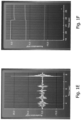
- Exemplary inertial data acquired by one or more acceleration sensors 110 comprised by an IMU are illustrated in Figs. 1E and 1F .
- the IMU typically comprises multiple acceleration sensors 110 aligned with different axes and indicative of different DOFs.
- Each accelerometer and gyroscope generates inertial data that can be received and analyzed. While only one accelerometer or gyroscope may be necessary for determining a need for re-registration as described herein, receiving inertial data from multiple such sources may improve the accuracy of determining a need of a re-registration.
- Fig. 1E shows an acceleration in m/s 2 of the tracker 100 as a function of time in s for three separate acceleration sensors 110 (here: accelerometers) supported by the tracker 100 and aligned with different axis.
- acceleration sensors 110 here: accelerometers
- multiple movements of the tracker 100 can be identified in the inertial data.
- all detected accelerations are below an acceleration threshold of, for example, 5 m/s 2 (or higher).
- These accelerations may be associated with controlled movements or at least with movements not indicating an impact on the tracker 100, that would give rise to a need for a re-registration.
- the acceleration beginning at 7,8 seconds shows a damped oscillation with an initial acceleration peak of over 20 m/s 2 .
- the acceleration threshold of 5 m/s 2 is exceeded, which indicates an impact on the tracker 100 and possibly a need for a re-registration.
- a need may alternatively, or additionally, be derived from the damped oscillation behavior of the signals illustrated in Fig. 1E .
- the data was standardized by subtracting a gravitational acceleration from the data.
- Fig. 1F shows three independent measurements as determined by three acceleration sensors 110 for three different DOFs (in m/s 2 as a function of time in s).
- the shown measurements are indicative of a gravity vector G in the position of the tracker 100.
- the measured acceleration indicative of the gravity vector G also changes.
- Such behavior can be seen at a time of around 21,5 to 22 seconds.
- the measured gravity vector changes and does not return to its initial value, which indicates a permanent positional change of the accelerometers of acceleration sensor 110, i.e., of the tracker 100. Therefore, a change of the acceleration indicative of the gravity vector G may form the basis of another, or alternative, predetermined condition indicative of a need for a re-registration (e.g., of drift of the tracker 100 or an impact on the tracker 100).
- Fig. 1G illustrates a schematic representation of coordinate transformations between the three coordinate systems COS_camera, COS_1st tracker and COS_medical image comprising the re-registration denoted as Re_Reg, determined analogous to the initial registrations Reg shown in Fig. 1B .
- Fig. 2A illustrates the surgical scenario of Fig. 1A with the patient tracker 100 additionally comprising a notification device 500 as an integral part thereof.
- the shown notification device 500 is an optical device, e.g., a LED or a LED configuration comprising multiple LEDs.
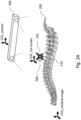
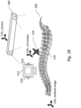
- FIG. 2B An example of a notification device 500 with multiple LEDs 501 switching from a first geometric pattern to a second geometric pattern is illustrated in Figs. 2B and 2C .
- Fig. 2B only three of the shown LEDs 501 emit light (displayed as a black circle with a white filling).
- Fig. 2C all of the LEDs 501 emit light.
- the notification device 500 is an acoustic device (e.g., a loudspeaker) or a combination of an optical and an acoustical device 500. Accordingly, the user notification signal that is output by the notification device 500 may be an optic or acoustic notification or a combination thereof.
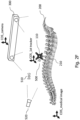
- Fig. 2D illustrates the surgical scenario of Fig. 1A with a notification device 510 that is separate from the patient tracker 100.
- the separate notification device 510 may in some variants be provided in addition to the integral notification device 500 of Fig. 2A .
- the separate notification device 510 is provided as an alternative to the integral notification device 500.
- the notification device 510 may be an optical or acoustical notification device or a combination thereof, analogous to the notification device 500 comprised by the patient tracker 100.
- the notification device 510 has a similar functionality as the notification device 500 of Fig 2A .
- the notification device 510 shown in Fig. 2D is a standalone device 510 that is in (e.g., wireless) communication with the tracker 100 to receive the re-registration signal.
- the notification device 510 is configured to receive the re-registration signal via radio frequency (RF) communication (using, e.g., Bluetooth technology) or via infrared (IR) communication.
- RF radio frequency
- IR infrared
- Fig. 2E illustrates the surgical scenario of Fig. 1A with another implementation of the notification device 510 that is separate from the tracker 110.
- the notification device 510 shown in Fig. 2E is comprised by a computing system 515 that is in communication with the patient tracker 100 to (e.g., wirelessly) receive the re-registration signal.
- the notification device 510 has a similar functionality as the notification device 500 of Fig 2A .
- the computing system 515 comprises a display and is configured to generate a pop-up window as notification signal.
- the separate notification device 510 may further be configured to generate a sound when the pop-up window is generated.
- Fig. 2F illustrates a combination of the surgical scenarios of Figs. 2A and 2D with an additional separate monitoring device 520.
- One or both of the notification devices 500, 510 are monitored by at least one of the camera system 300 and the separate monitoring device 520.
- the separate monitoring device 520 may comprise at least one of a camera, a microphone, an IR-receiver and a radio frequency receiver (e.g., a Bluetooth receiver).
- the re-registration signal is configured to trigger the re-registration notification to one or both of the separate monitoring device 520 and the camera system 300.
- a second re-registration signal is generated.
- the second re-registration signal is configured to trigger an automatic re-registration of COS_1st tracker with COS_medical image.
- the second re-registration signal triggers an automatic user notification suggesting to a user to trigger the re-registration.
- Fig. 2G illustrates a schematic representation of a system for visualizing image data representative of the patient tracker 100 and its environment.
- the image data to be visualized is generated by at least one of the camera system 300, the monitoring device 520 and separate camera (not shown) that continuously images the tracker 100.
- the image data thus obtained is intended to be visualized, e.g., on a display 530, in the field of view of a user.
- the image data is, for example, continuously stored in a ring buffer of a certain size (e.g., sufficient to store at least 10 seconds of image data).
- the image data is configured to be replayed when an unintended movement of the patient tracker 100 (in particular an impact) is detected.
- the image data is visualized in response to a manual input of a user (e.g., in response to the notification being output by the notification device 500) or automatically.
- the visualization of the image data may help a user identifying the kind of detected tracker movement and deciding whether or not a re-registration is necessary.
- the visualization may reduce cognitive load on a surgeon and duration of a surgery.
- Fig. 3A illustrates the surgical scenario of Fig. 1A with an additional second patient tracker 600 associated with a coordinate system COS_2nd tracker. Similar to the first patient tracker 100, the second patient tracker 600 comprises a second acceleration sensor 610. The second acceleration sensor 610 is configured to acquire inertial data indicative of an acceleration of the second tracker 600, analogous to the first acceleration sensor 110 of the first tracker 100.
- the first tracker 100 and the second tracker 600 are attached to different vertebra 210, 620 of the patient anatomy 200.
- the camera system 300 is provided for optically tracking the first tracker 100 and the second tracker 600.
- the image data of the second tracker 600 generated by the camera system 300 are also associated with the camera coordinate system COS_camera.
- the coordinate transformations between COS_1st tracker, COS_camera and COS_medical image as described with reference to Figs. 1B, 1C and 1G may be analogously defined for the coordinate systems COS_2nd tracker, COS_camera and COS_medical image.
- An initial registration between between COS_2nd tracker and COS_medical image is denoted as Reg_2 in the following.
- COS_camera is related to both COS_1st tracker and COS_2nd tracker
- a coordinate transformation T_tracker (and its inverse transformation T_tracker ⁇ -1) between the two tracker coordinate systems COS_1st tracker and COS_2nd tracker is derivable.
- Fig. 3B illustrates a flow diagram 700 of a method variant for determining a need for a re-registration of the patient tracker 100 attached to the patient anatomy 200.
- the three steps 710, 720, and 730 are performed analogously to the method described with reference to Fig. 1D , i.e., receiving and analyzing inertial data from the first acceleration sensor 110 and generating a first re-registration signal, when the at least one first predetermined condition is fulfilled, except for a possible modification of step 730 compared to step 430.
- step 750 the inertial data received from the second acceleration sensor 610, or data derived therefrom, are analyzed with respect to at least one second predetermined condition indicative of a drift of the second tracker 600 or an impact on the second tracker 600.
- the second predetermined condition may be the same as the first predetermined condition (e.g., as explained above with reference to step 420 of Fig. 1D ) or different therefrom.
- Steps 710 and 720 as well as steps 740 and 750 may be performed substantially in parallel, as indicated in Fig. 3B .
- step 760 if the at least one second predetermined condition is not fulfilled (i.e., if Reg_2 is still considered to be correct) while the first predetermined condition is fulfilled, a re-registration of COS_1st tracker with COS_medical image based on Reg_2 and T_Tracker is automatically executed, or is suggested to a user, via the re-registration signal generated in step 730.
- step 730 may thus be integrated in step 760 (i.e., be a sub-step thereof).
- a re-registration of a coordinate system associated with the respective tracker 100, 600 can be performed based on the registration of the coordinate system associated with the other one of the first and second tracker 100, 600.
- Fig. 4A illustrates a schematic representation of the surgical scenario of Fig. 1A with the camera system 300 comprising a dedicated acceleration sensor 800.
- the acceleration sensor 800 is configured to generate inertial data indicative of an acceleration of the camera system 300.
- a need for re-registration of the patient tracker 100 may be determined based on the image data generated by the camera system 300 in combination with the inertial data of the third acceleration sensor 800.
- Fig. 4B illustrates a flow diagram 900 of a corresponding method variant for determining a need for a re-registration of the tracker 100.
- the three steps 910, 920, and 930 are performed analogously to the method described with reference to Fig. 1D , i.e., receiving and analyzing inertial data from the acceleration sensor 110 and generating a re-registration signal when the at least one first predetermined condition is fulfilled, except for a possible modification of step 930 compared to step 430.
- the re-registration signal may trigger at least one of a re-registration notification and an automatic re-registration, or a suggestion of a re-registration, similar to the re-registration signal described with reference to Fig. 1D .
- the method further comprises a step 940 of receiving image data generated by the camera system 300 and a step 950 of analyzing the received image data for a positional change of the tracker 100, i.e., for a relative movement between the tracker 100 and the camera system 300.
- Analyzing the received image data for a positional change of the tracker 100 may comprise determining first and second pixel coordinates of a center of at least one of the tracker 100 and each of the one or more markers of the tracker 100.
- the first pixel coordinates may be determined from image data taken in a situation without any movement of the tracker 100 or the camera system 300, e.g., directly after the initial registration process.
- the second pixel coordinates may be determined from the image data received in step 410.
- a difference between the first and second pixel coordinates may be indicative of a positional change of the tracker 100. Based on the the amount of the difference and/or the duration in which the indicated positional change takes place, the positional change of the tracker 100 may be indicative of at least one of a drift of the tracker and an impact on the tracker 100.
- step 960 At least the inertial data generated by the third acceleration sensor 800 is received in step 960.
- the received data, or data derived therefrom, are analyzed in step 970 with respect to at least one further predetermined condition indicative of an impact on the camera system 300.
- the at least one further predetermined condition indicative of an impact on the camera system 300 may be analogous to the at least one predetermined condition indicative of an impact on the tracker 100 as explained with reference to Fig. 1D above (or it may be different therefrom).
- Steps 910 and 920, steps 940 and 950 as well as steps 960 and 970 may be performed substantially in parallel, as indicated in Fig. 4B .
- the first re-registration signal is generated in case a positional change of the tracker 100 is identified based on the camera image data while the first predetermined condition is fulfilled.
- the first re-registration signal is generated in case the inertial data generated by the third acceleration sensor 800 is not indicative of an impact on the camera system 300 while the first predetermined condition is fulfilled.
- the re-registration signal generated in step 930 triggers generation of a re-registration notification for further facilitating decision-making of a surgeon, e.g., regarding the need of a suggested re-registration of the tracker 100, i.e., of COS_1st tracker with COS_medicalimage.
- the accuracy of the determination of the need for a re-registration may be increased since the optical data-based determination may be utilized to compensate for possible deficits of the inertial data-based determination and vice versa.
- a determination based on optical tracking requires a line of sight from the camera system 300 to the tracker 100, 600.
- a determination based on inertial data on the other hand is applicable without the need for any line of sight.
- any inertial data generated by an acceleration sensor 110, 610, 800 is subject to integration drift, as explained above. Image data generated by a camera system 300 on the other hand are only subject to a positional drift of the camera system 300 or the tracker 100, 600.
- Data generated by the camera system 300 and any of the acceleration sensors 110, 610, 800 as described above may be received in near real time.
- the generated data from the camera system 300 and any or all of the acceleration sensors 110, 610, 800 may be received substantially in parallel. Alternatively, some or all of the generated data may be received in sequence.
- the inertial data from the third acceleration sensor 800 may only be received when a positional change of the first tracker100 is indicated in the received image data. In this case, the inertial data may be associated with the corresponding image data based on time stamps. As a result, usage of energy and data transmitting resources may be reduced.
- Fig. 5 illustrates a schematic representation of a data processing system 1000 for detecting an unintended movement of a tracker 100 attached to a patient anatomy 200.
- the data processing system 1000 comprises one or more processors 1010 configured to perform the steps of the flow diagrams 400, 700, 900 described herein.
- the data processing system 1000 is built from cloud computing resources.
- the data processing system 1000 is physically located in an operating room.
- Fig. 6 illustrates a schematic representation of a computer program product 1100 comprising instructions 1110 configured to perform the steps of the methods of flow diagrams 400, 700, 900 when executed on one or more processors, e.g., on the one or more processors 1010 of the data processing system 1000 shown in Fig. 5 .
- the technique presented herein enables continuously maintaining a high registration quality. Any temporal interval a surgeon operates on the basis of an incorrect registration is minimized, since a possible time gap between an unintended tracker movement relative to the patient anatomy 200 and a re-registration for compensating the resulting inaccuracy can be minimized.
Landscapes
- Engineering & Computer Science (AREA)
- Health & Medical Sciences (AREA)
- Surgery (AREA)
- Life Sciences & Earth Sciences (AREA)
- Medical Informatics (AREA)
- General Health & Medical Sciences (AREA)
- Public Health (AREA)
- Biomedical Technology (AREA)
- Nuclear Medicine, Radiotherapy & Molecular Imaging (AREA)
- Animal Behavior & Ethology (AREA)
- Molecular Biology (AREA)
- Heart & Thoracic Surgery (AREA)
- Veterinary Medicine (AREA)
- Computer Vision & Pattern Recognition (AREA)
- General Physics & Mathematics (AREA)
- Theoretical Computer Science (AREA)
- Physics & Mathematics (AREA)
- Robotics (AREA)
- Epidemiology (AREA)
- Primary Health Care (AREA)
- General Business, Economics & Management (AREA)
- Business, Economics & Management (AREA)
- Radiology & Medical Imaging (AREA)
- Pathology (AREA)
- Oral & Maxillofacial Surgery (AREA)
- Multimedia (AREA)
- Ultra Sonic Daignosis Equipment (AREA)
Priority Applications (1)
| Application Number | Priority Date | Filing Date | Title |
|---|---|---|---|
| EP25159845.4A EP4537785A3 (de) | 2022-01-18 | 2022-01-18 | Verfahren zur bestimmung des bedarfs einer neuregistrierung eines patientenverfolgers |
Applications Claiming Priority (2)
| Application Number | Priority Date | Filing Date | Title |
|---|---|---|---|
| EP25159845.4A EP4537785A3 (de) | 2022-01-18 | 2022-01-18 | Verfahren zur bestimmung des bedarfs einer neuregistrierung eines patientenverfolgers |
| EP22151995.2A EP4212122B1 (de) | 2022-01-18 | 2022-01-18 | Technik zur bestimmung der notwendigkeit einer neuregistrierung eines patientenverfolgers |
Related Parent Applications (1)
| Application Number | Title | Priority Date | Filing Date |
|---|---|---|---|
| EP22151995.2A Division EP4212122B1 (de) | 2022-01-18 | 2022-01-18 | Technik zur bestimmung der notwendigkeit einer neuregistrierung eines patientenverfolgers |
Publications (2)
| Publication Number | Publication Date |
|---|---|
| EP4537785A2 true EP4537785A2 (de) | 2025-04-16 |
| EP4537785A3 EP4537785A3 (de) | 2025-06-11 |
Family
ID=80445688
Family Applications (2)
| Application Number | Title | Priority Date | Filing Date |
|---|---|---|---|
| EP22151995.2A Active EP4212122B1 (de) | 2022-01-18 | 2022-01-18 | Technik zur bestimmung der notwendigkeit einer neuregistrierung eines patientenverfolgers |
| EP25159845.4A Pending EP4537785A3 (de) | 2022-01-18 | 2022-01-18 | Verfahren zur bestimmung des bedarfs einer neuregistrierung eines patientenverfolgers |
Family Applications Before (1)
| Application Number | Title | Priority Date | Filing Date |
|---|---|---|---|
| EP22151995.2A Active EP4212122B1 (de) | 2022-01-18 | 2022-01-18 | Technik zur bestimmung der notwendigkeit einer neuregistrierung eines patientenverfolgers |
Country Status (3)
| Country | Link |
|---|---|
| US (1) | US20230225797A1 (de) |
| EP (2) | EP4212122B1 (de) |
| CN (1) | CN116468757A (de) |
Families Citing this family (1)
| Publication number | Priority date | Publication date | Assignee | Title |
|---|---|---|---|---|
| WO2025158388A1 (en) * | 2024-01-25 | 2025-07-31 | Medtronic Navigation, Inc. | System and method for determining a status of a tracking device |
Citations (1)
| Publication number | Priority date | Publication date | Assignee | Title |
|---|---|---|---|---|
| US20190090955A1 (en) | 2016-03-01 | 2019-03-28 | Mirus Llc | Systems and methods for position and orientation tracking of anatomy and surgical instruments |
Family Cites Families (14)
| Publication number | Priority date | Publication date | Assignee | Title |
|---|---|---|---|---|
| EP1958586A1 (de) * | 2007-02-19 | 2008-08-20 | BrainLAB AG | Chirurgische Vorrichtung mit Stoßfeststeller |
| KR101645392B1 (ko) * | 2014-08-13 | 2016-08-02 | 주식회사 고영테크놀러지 | 트랙킹 시스템 및 이를 이용한 트랙킹 방법 |
| WO2017087371A1 (en) * | 2015-11-16 | 2017-05-26 | Think Surgical, Inc. | Method for confirming registration of tracked bones |
| EP3528735A4 (de) * | 2016-10-21 | 2020-04-29 | Mobius Imaging LLC | Verfahren und systeme zur einstellung von trajektorien und zielorten für die bildgeführte chirurgie |
| US10441365B2 (en) * | 2017-01-11 | 2019-10-15 | Synaptive Medical (Barbados) Inc. | Patient reference device |
| DE102019004235B4 (de) * | 2018-07-16 | 2024-01-18 | Mako Surgical Corp. | System und verfahren zur bildbasierten registrierung und kalibrierung |
| JP7617115B2 (ja) * | 2020-01-13 | 2025-01-17 | ストライカー・コーポレイション | ナビゲーション支援手術中にオフセットをモニタするシステム及び方法 |
| WO2022066710A1 (en) * | 2020-09-22 | 2022-03-31 | Mobius Imaging, Llc | Mount assemblies for use with navigated surgical systems |
| US12602775B2 (en) * | 2021-10-20 | 2026-04-14 | Globus Medical Inc. | Interpolation of medical images |
| EP4212123B1 (de) * | 2022-01-18 | 2025-04-23 | Stryker European Operations Limited | Technik zur bestimmung der notwendigkeit einer neuregistrierung eines von einem kamerasystem verfolgten patientenverfolgers |
| US12279834B2 (en) * | 2022-02-08 | 2025-04-22 | The Cleveland Clinic Foundation | Detection of unintentional movement of a reference marker and automatic re-registration |
| US12394086B2 (en) * | 2022-05-10 | 2025-08-19 | Globus Medical, Inc. | Accuracy check and automatic calibration of tracked instruments |
| US12318150B2 (en) * | 2022-10-11 | 2025-06-03 | Globus Medical Inc. | Camera tracking system for computer assisted surgery navigation |
| WO2025137057A1 (en) * | 2023-12-18 | 2025-06-26 | Mako Surgical Corp. | Hybrid optical-inertial bone tracking |
-
2022
- 2022-01-18 EP EP22151995.2A patent/EP4212122B1/de active Active
- 2022-01-18 EP EP25159845.4A patent/EP4537785A3/de active Pending
-
2023
- 2023-01-16 US US18/097,393 patent/US20230225797A1/en active Pending
- 2023-01-17 CN CN202310072476.5A patent/CN116468757A/zh active Pending
Patent Citations (1)
| Publication number | Priority date | Publication date | Assignee | Title |
|---|---|---|---|---|
| US20190090955A1 (en) | 2016-03-01 | 2019-03-28 | Mirus Llc | Systems and methods for position and orientation tracking of anatomy and surgical instruments |
Also Published As
| Publication number | Publication date |
|---|---|
| US20230225797A1 (en) | 2023-07-20 |
| EP4212122A1 (de) | 2023-07-19 |
| EP4212122B1 (de) | 2025-02-26 |
| EP4537785A3 (de) | 2025-06-11 |
| CN116468757A (zh) | 2023-07-21 |
Similar Documents
| Publication | Publication Date | Title |
|---|---|---|
| US11275249B2 (en) | Augmented visualization during surgery | |
| US20230225796A1 (en) | Technique For Determining A Need For A Re-Registration Of A Patient Tracker Tracked By A Camera System | |
| US20200237449A1 (en) | Redundant reciprocal tracking system | |
| EP3445267B1 (de) | Verfahren und system zur registrierungsprüfung | |
| US20200129240A1 (en) | Systems and methods for intraoperative planning and placement of implants | |
| US20210052348A1 (en) | An Augmented Reality Surgical Guidance System | |
| EP2765946B1 (de) | Medizinisches verfolgungssystem mit einer multifunktionellen sensorvorrichtung | |
| KR20130135147A (ko) | 의료 영상 장치 안에서 환자 지지 장치 위에 배치된 하나 이상의 물체에 관한 정보를 수집하는 방법 및 그 실시를 위한 의료 영상 장치 | |
| US20210052329A1 (en) | Monitoring of moving objects in an operation room | |
| JP2018509204A (ja) | 顎の動きの追跡 | |
| US12211221B2 (en) | Systems and methods for enhancement of 3D imagery and navigation via integration of patient motion data | |
| US20050062469A1 (en) | System and method for hemisphere disambiguation in electromagnetic tracking systems | |
| US20230225797A1 (en) | Technique For Determining A Need For A Re-Registration Of A Patient Tracker | |
| JP2017176773A (ja) | 手術支援システム、手術支援方法、手術支援プログラム | |
| US12406396B2 (en) | Microscope camera calibration | |
| US12361557B2 (en) | Systems and methods for monitoring one or more anatomical elements | |
| US6810280B2 (en) | Method and apparatus for detecting the three-dimensional position of an examination instrument inserted into a body region | |
| He et al. | Sensor-fusion based augmented-reality surgical navigation system | |
| JP2009172124A (ja) | 手術ナビゲーションシステム、画像表示方法、コンピュータプログラム及び記録媒体 | |
| JP7511555B2 (ja) | 画像装置のための空間的位置合わせ方法 | |
| EP4264545B1 (de) | Systeme und verfahren zur überwachung eines oder mehrerer anatomischer elemente | |
| EP4461252A1 (de) | Systeme und verfahren zur verfolgung von interessensorten in der endoskopischen bildgebung | |
| US20250157058A1 (en) | System And Methods For Enhancement Of 3D Imagery And Navigation Via Integration Of Patient Motion Data | |
| WO2024125773A1 (en) | Wide angle navigation system | |
| CN117012342A (zh) | 用于基于估计的外科医生姿态确定造影的技术 |
Legal Events
| Date | Code | Title | Description |
|---|---|---|---|
| PUAI | Public reference made under article 153(3) epc to a published international application that has entered the european phase |
Free format text: ORIGINAL CODE: 0009012 |
|
| STAA | Information on the status of an ep patent application or granted ep patent |
Free format text: STATUS: THE APPLICATION HAS BEEN PUBLISHED |
|
| AC | Divisional application: reference to earlier application |
Ref document number: 4212122 Country of ref document: EP Kind code of ref document: P |
|
| AK | Designated contracting states |
Kind code of ref document: A2 Designated state(s): AL AT BE BG CH CY CZ DE DK EE ES FI FR GB GR HR HU IE IS IT LI LT LU LV MC MK MT NL NO PL PT RO RS SE SI SK SM TR |
|
| REG | Reference to a national code |
Ref country code: DE Ref legal event code: R079 Free format text: PREVIOUS MAIN CLASS: A61B0090000000 Ipc: A61B0034200000 |
|
| PUAL | Search report despatched |
Free format text: ORIGINAL CODE: 0009013 |
|
| AK | Designated contracting states |
Kind code of ref document: A3 Designated state(s): AL AT BE BG CH CY CZ DE DK EE ES FI FR GB GR HR HU IE IS IT LI LT LU LV MC MK MT NL NO PL PT RO RS SE SI SK SM TR |
|
| RIC1 | Information provided on ipc code assigned before grant |
Ipc: A61B 90/00 20160101ALI20250508BHEP Ipc: A61B 34/20 20160101AFI20250508BHEP |
|
| STAA | Information on the status of an ep patent application or granted ep patent |
Free format text: STATUS: REQUEST FOR EXAMINATION WAS MADE |
|
| 17P | Request for examination filed |
Effective date: 20251204 |