EP4538106A1 - Chargeur embarqué bidirectionnel, système d'alimentation embarqué et véhicule électrique - Google Patents
Chargeur embarqué bidirectionnel, système d'alimentation embarqué et véhicule électrique Download PDFInfo
- Publication number
- EP4538106A1 EP4538106A1 EP23834467.5A EP23834467A EP4538106A1 EP 4538106 A1 EP4538106 A1 EP 4538106A1 EP 23834467 A EP23834467 A EP 23834467A EP 4538106 A1 EP4538106 A1 EP 4538106A1
- Authority
- EP
- European Patent Office
- Prior art keywords
- switch
- alternating current
- bidirectional
- bridge arm
- board charger
- Prior art date
- Legal status (The legal status is an assumption and is not a legal conclusion. Google has not performed a legal analysis and makes no representation as to the accuracy of the status listed.)
- Pending
Links
Images





Classifications
-
- B—PERFORMING OPERATIONS; TRANSPORTING
- B60—VEHICLES IN GENERAL
- B60L—PROPULSION OF ELECTRICALLY-PROPELLED VEHICLES; SUPPLYING ELECTRIC POWER FOR AUXILIARY EQUIPMENT OF ELECTRICALLY-PROPELLED VEHICLES; ELECTRODYNAMIC BRAKE SYSTEMS FOR VEHICLES IN GENERAL; MAGNETIC SUSPENSION OR LEVITATION FOR VEHICLES; MONITORING OPERATING VARIABLES OF ELECTRICALLY-PROPELLED VEHICLES; ELECTRIC SAFETY DEVICES FOR ELECTRICALLY-PROPELLED VEHICLES
- B60L53/00—Methods of charging batteries, specially adapted for electric vehicles; Charging stations or on-board charging equipment therefor; Exchange of energy storage elements in electric vehicles
- B60L53/20—Methods of charging batteries, specially adapted for electric vehicles; Charging stations or on-board charging equipment therefor; Exchange of energy storage elements in electric vehicles characterised by converters located in the vehicle
- B60L53/24—Using the vehicle's propulsion converter for charging
-
- B—PERFORMING OPERATIONS; TRANSPORTING
- B60—VEHICLES IN GENERAL
- B60L—PROPULSION OF ELECTRICALLY-PROPELLED VEHICLES; SUPPLYING ELECTRIC POWER FOR AUXILIARY EQUIPMENT OF ELECTRICALLY-PROPELLED VEHICLES; ELECTRODYNAMIC BRAKE SYSTEMS FOR VEHICLES IN GENERAL; MAGNETIC SUSPENSION OR LEVITATION FOR VEHICLES; MONITORING OPERATING VARIABLES OF ELECTRICALLY-PROPELLED VEHICLES; ELECTRIC SAFETY DEVICES FOR ELECTRICALLY-PROPELLED VEHICLES
- B60L1/00—Supplying electric power to auxiliary equipment of vehicles
- B60L1/006—Supplying electric power to auxiliary equipment of vehicles to power outlets
-
- B—PERFORMING OPERATIONS; TRANSPORTING
- B60—VEHICLES IN GENERAL
- B60L—PROPULSION OF ELECTRICALLY-PROPELLED VEHICLES; SUPPLYING ELECTRIC POWER FOR AUXILIARY EQUIPMENT OF ELECTRICALLY-PROPELLED VEHICLES; ELECTRODYNAMIC BRAKE SYSTEMS FOR VEHICLES IN GENERAL; MAGNETIC SUSPENSION OR LEVITATION FOR VEHICLES; MONITORING OPERATING VARIABLES OF ELECTRICALLY-PROPELLED VEHICLES; ELECTRIC SAFETY DEVICES FOR ELECTRICALLY-PROPELLED VEHICLES
- B60L53/00—Methods of charging batteries, specially adapted for electric vehicles; Charging stations or on-board charging equipment therefor; Exchange of energy storage elements in electric vehicles
- B60L53/20—Methods of charging batteries, specially adapted for electric vehicles; Charging stations or on-board charging equipment therefor; Exchange of energy storage elements in electric vehicles characterised by converters located in the vehicle
- B60L53/22—Constructional details or arrangements of charging converters specially adapted for charging electric vehicles
-
- B—PERFORMING OPERATIONS; TRANSPORTING
- B60—VEHICLES IN GENERAL
- B60L—PROPULSION OF ELECTRICALLY-PROPELLED VEHICLES; SUPPLYING ELECTRIC POWER FOR AUXILIARY EQUIPMENT OF ELECTRICALLY-PROPELLED VEHICLES; ELECTRODYNAMIC BRAKE SYSTEMS FOR VEHICLES IN GENERAL; MAGNETIC SUSPENSION OR LEVITATION FOR VEHICLES; MONITORING OPERATING VARIABLES OF ELECTRICALLY-PROPELLED VEHICLES; ELECTRIC SAFETY DEVICES FOR ELECTRICALLY-PROPELLED VEHICLES
- B60L55/00—Arrangements for supplying energy stored within a vehicle to a power network, i.e. vehicle-to-grid [V2G] arrangements
-
- H—ELECTRICITY
- H02—GENERATION; CONVERSION OR DISTRIBUTION OF ELECTRIC POWER
- H02J—ELECTRIC POWER NETWORKS; CIRCUIT ARRANGEMENTS OR SYSTEMS FOR SUPPLYING OR DISTRIBUTING ELECTRIC POWER; SYSTEMS FOR STORING ELECTRIC ENERGY
- H02J7/00—Circuit arrangements for charging or discharging batteries or for supplying loads from batteries
- H02J7/02—Circuit arrangements for charging or discharging batteries or for supplying loads from batteries for charging batteries from AC mains by converters
-
- H—ELECTRICITY
- H02—GENERATION; CONVERSION OR DISTRIBUTION OF ELECTRIC POWER
- H02M—APPARATUS FOR CONVERSION BETWEEN AC AND AC, BETWEEN AC AND DC, OR BETWEEN DC AND DC, AND FOR USE WITH MAINS OR SIMILAR POWER SUPPLY SYSTEMS; CONVERSION OF DC OR AC INPUT POWER INTO SURGE OUTPUT POWER; CONTROL OR REGULATION THEREOF
- H02M1/00—Details of apparatus for conversion
- H02M1/0067—Converter structures employing plural converter units, other than for parallel operation of the units on a single load
- H02M1/007—Plural converter units in cascade
-
- H—ELECTRICITY
- H02—GENERATION; CONVERSION OR DISTRIBUTION OF ELECTRIC POWER
- H02M—APPARATUS FOR CONVERSION BETWEEN AC AND AC, BETWEEN AC AND DC, OR BETWEEN DC AND DC, AND FOR USE WITH MAINS OR SIMILAR POWER SUPPLY SYSTEMS; CONVERSION OF DC OR AC INPUT POWER INTO SURGE OUTPUT POWER; CONTROL OR REGULATION THEREOF
- H02M1/00—Details of apparatus for conversion
- H02M1/42—Circuits or arrangements for compensating for or adjusting power factor in converters or inverters
- H02M1/4208—Arrangements for improving power factor of AC input
- H02M1/4216—Arrangements for improving power factor of AC input operating from a three-phase input voltage
-
- H—ELECTRICITY
- H02—GENERATION; CONVERSION OR DISTRIBUTION OF ELECTRIC POWER
- H02M—APPARATUS FOR CONVERSION BETWEEN AC AND AC, BETWEEN AC AND DC, OR BETWEEN DC AND DC, AND FOR USE WITH MAINS OR SIMILAR POWER SUPPLY SYSTEMS; CONVERSION OF DC OR AC INPUT POWER INTO SURGE OUTPUT POWER; CONTROL OR REGULATION THEREOF
- H02M1/00—Details of apparatus for conversion
- H02M1/42—Circuits or arrangements for compensating for or adjusting power factor in converters or inverters
- H02M1/4208—Arrangements for improving power factor of AC input
- H02M1/4233—Arrangements for improving power factor of AC input using a bridge converter comprising active switches
-
- B—PERFORMING OPERATIONS; TRANSPORTING
- B60—VEHICLES IN GENERAL
- B60L—PROPULSION OF ELECTRICALLY-PROPELLED VEHICLES; SUPPLYING ELECTRIC POWER FOR AUXILIARY EQUIPMENT OF ELECTRICALLY-PROPELLED VEHICLES; ELECTRODYNAMIC BRAKE SYSTEMS FOR VEHICLES IN GENERAL; MAGNETIC SUSPENSION OR LEVITATION FOR VEHICLES; MONITORING OPERATING VARIABLES OF ELECTRICALLY-PROPELLED VEHICLES; ELECTRIC SAFETY DEVICES FOR ELECTRICALLY-PROPELLED VEHICLES
- B60L2210/00—Converter types
- B60L2210/30—AC to DC converters
-
- B—PERFORMING OPERATIONS; TRANSPORTING
- B60—VEHICLES IN GENERAL
- B60L—PROPULSION OF ELECTRICALLY-PROPELLED VEHICLES; SUPPLYING ELECTRIC POWER FOR AUXILIARY EQUIPMENT OF ELECTRICALLY-PROPELLED VEHICLES; ELECTRODYNAMIC BRAKE SYSTEMS FOR VEHICLES IN GENERAL; MAGNETIC SUSPENSION OR LEVITATION FOR VEHICLES; MONITORING OPERATING VARIABLES OF ELECTRICALLY-PROPELLED VEHICLES; ELECTRIC SAFETY DEVICES FOR ELECTRICALLY-PROPELLED VEHICLES
- B60L2210/00—Converter types
- B60L2210/40—DC to AC converters
- B60L2210/44—Current source inverters
-
- H—ELECTRICITY
- H02—GENERATION; CONVERSION OR DISTRIBUTION OF ELECTRIC POWER
- H02J—ELECTRIC POWER NETWORKS; CIRCUIT ARRANGEMENTS OR SYSTEMS FOR SUPPLYING OR DISTRIBUTING ELECTRIC POWER; SYSTEMS FOR STORING ELECTRIC ENERGY
- H02J2105/00—Networks for supplying or distributing electric power characterised by their spatial reach or by the load
- H02J2105/30—Networks for supplying or distributing electric power characterised by their spatial reach or by the load the load networks being external to vehicles, i.e. exchanging power with vehicles
- H02J2105/33—Networks for supplying or distributing electric power characterised by their spatial reach or by the load the load networks being external to vehicles, i.e. exchanging power with vehicles exchanging power with road vehicles
- H02J2105/37—Networks for supplying or distributing electric power characterised by their spatial reach or by the load the load networks being external to vehicles, i.e. exchanging power with vehicles exchanging power with road vehicles exchanging power with electric vehicles [EV] or with hybrid electric vehicles [HEV]
-
- H—ELECTRICITY
- H02—GENERATION; CONVERSION OR DISTRIBUTION OF ELECTRIC POWER
- H02J—ELECTRIC POWER NETWORKS; CIRCUIT ARRANGEMENTS OR SYSTEMS FOR SUPPLYING OR DISTRIBUTING ELECTRIC POWER; SYSTEMS FOR STORING ELECTRIC ENERGY
- H02J2207/00—Details of circuit arrangements for charging or discharging batteries or supplying loads from batteries
- H02J2207/20—Charging or discharging characterised by the power electronics converter
-
- Y—GENERAL TAGGING OF NEW TECHNOLOGICAL DEVELOPMENTS; GENERAL TAGGING OF CROSS-SECTIONAL TECHNOLOGIES SPANNING OVER SEVERAL SECTIONS OF THE IPC; TECHNICAL SUBJECTS COVERED BY FORMER USPC CROSS-REFERENCE ART COLLECTIONS [XRACs] AND DIGESTS
- Y02—TECHNOLOGIES OR APPLICATIONS FOR MITIGATION OR ADAPTATION AGAINST CLIMATE CHANGE
- Y02T—CLIMATE CHANGE MITIGATION TECHNOLOGIES RELATED TO TRANSPORTATION
- Y02T10/00—Road transport of goods or passengers
- Y02T10/60—Other road transportation technologies with climate change mitigation effect
- Y02T10/70—Energy storage systems for electromobility, e.g. batteries
-
- Y—GENERAL TAGGING OF NEW TECHNOLOGICAL DEVELOPMENTS; GENERAL TAGGING OF CROSS-SECTIONAL TECHNOLOGIES SPANNING OVER SEVERAL SECTIONS OF THE IPC; TECHNICAL SUBJECTS COVERED BY FORMER USPC CROSS-REFERENCE ART COLLECTIONS [XRACs] AND DIGESTS
- Y02—TECHNOLOGIES OR APPLICATIONS FOR MITIGATION OR ADAPTATION AGAINST CLIMATE CHANGE
- Y02T—CLIMATE CHANGE MITIGATION TECHNOLOGIES RELATED TO TRANSPORTATION
- Y02T10/00—Road transport of goods or passengers
- Y02T10/60—Other road transportation technologies with climate change mitigation effect
- Y02T10/7072—Electromobility specific charging systems or methods for batteries, ultracapacitors, supercapacitors or double-layer capacitors
-
- Y—GENERAL TAGGING OF NEW TECHNOLOGICAL DEVELOPMENTS; GENERAL TAGGING OF CROSS-SECTIONAL TECHNOLOGIES SPANNING OVER SEVERAL SECTIONS OF THE IPC; TECHNICAL SUBJECTS COVERED BY FORMER USPC CROSS-REFERENCE ART COLLECTIONS [XRACs] AND DIGESTS
- Y02—TECHNOLOGIES OR APPLICATIONS FOR MITIGATION OR ADAPTATION AGAINST CLIMATE CHANGE
- Y02T—CLIMATE CHANGE MITIGATION TECHNOLOGIES RELATED TO TRANSPORTATION
- Y02T90/00—Enabling technologies or technologies with a potential or indirect contribution to GHG emissions mitigation
- Y02T90/10—Technologies relating to charging of electric vehicles
- Y02T90/14—Plug-in electric vehicles
Definitions
- This application relates to the field of power electronics technologies, and in particular, to a bidirectional on-board charger, an Vehicle power system, and an electric vehicle.
- an on-board charger (on-board charger, OBC) is a charger fixedly mounted on an electric vehicle.
- An alternating current side of the on-board charger is connected to an alternating current power grid, and a direct current side of the on-board charger is connected to a power battery.
- the on-board charger is configured to convert an output voltage of the alternating current power grid into a direct current voltage to charge the power battery.
- the on-board charger cannot meet a requirement for charging the external load, and consequently applicability is poor.
- This application provides a bidirectional on-board charger, an Vehicle power system, and an electric vehicle, so that the bidirectional on-board charger is compatible with a forward charging function of charging a power battery and a reverse discharging function of supplying power to an alternating current load, thereby greatly reducing circuit costs. Therefore, operational flexibility is high, and applicability is high.
- this application provides a bidirectional on-board charger, configured to charge a power battery by using a three-phase alternating current power supply or supply power to an alternating current load by using a power battery.
- the bidirectional on-board charger includes:
- the first switch and the three second bridge arms may be controlled to cooperate with each other, so that a forward charging function of charging the power battery and a reverse discharging function of supplying power to the alternating current load are implemented, thereby greatly reducing circuit costs. Therefore, operational flexibility is high, and applicability is high.
- the first bridge arm includes two diodes connected in series.
- a series connection point of the two diodes serves as the midpoint of the first bridge arm, and therefore costs of the bridge arm are lower.
- the second bridge arm includes a second switch and a third switch connected in series, and a series connection point of the second switch and the third switch serves as a midpoint of the second bridge arm.
- the controller is configured to:
- actions of some or all second bridge arms in the three second bridge arms are controlled, so that the single-phase alternating current may be converted into the direct current, or the direct current may be converted into the alternating current, or the three-phase alternating current may be converted into the direct current, thereby meeting different working requirements of the bidirectional on-board charger. Therefore, operational flexibility is high.
- the bidirectional on-board charger includes three fourth switches corresponding to the three second bridge arms, and a midpoint of one of the second bridge arms is connected to one live wire of the three-phase alternating current power supply or a first connection terminal of the alternating current load through a fourth switch corresponding to the second bridge arm.
- the midpoints of the three second bridge arms, the three fourth switches, and three live wires of the three-phase alternating current power supply are in one-to-one correspondence and connected.
- the controller is configured to:
- each of the three fourth switches and the fifth switch is controlled to be turned on or turned off, so that the midpoint of the second bridge arm may receive the single-phase alternating current or output the alternating current, thereby meeting different working requirements of the bidirectional on-board charger. Therefore, operational flexibility is high.
- the three second bridge arms include the other two of the second bridge arms other than a second bridge arm corresponding to the any one of the fourth switches
- the bidirectional on-board charger includes two fifth switches corresponding to the other two of the second bridge arms.
- a midpoint of any one of the other two of the second bridge arms is connected to a first connection end of the any one of the fourth switches through a fifth switch corresponding to the second bridge arm, and the first connection end of the any one of the fourth switches is connected to one live wire of the three-phase alternating current power supply or the first connection terminal of the alternating current load.
- Midpoints of the other two of the second bridge arms and the two fifth switches are in one-to-one correspondence and connected.
- the controller is configured to:
- each of the three fourth switches and the two fifth switches is controlled to be turned on or turned off, so that the midpoint of the second bridge arm may receive the single-phase alternating current or output the alternating current, thereby meeting different working requirements of the bidirectional on-board charger. Therefore, operational flexibility is high.
- the bidirectional on-board charger includes a sixth switch, a midpoint of any one of the second bridge arms is connected to a neutral wire of the three-phase alternating current power supply through the sixth switch, and the bidirectional on-board charger is configured to charge the power battery by using the three-phase alternating current power supply.
- the controller is configured to: control the sixth switch to be turned off, so that the forward charging function of charging the power battery is implemented.
- the bidirectional on-board charger includes a sixth switch, a midpoint of any one of the second bridge arms is connected to a second connection terminal of the alternating current load through the sixth switch, and the bidirectional on-board charger is configured to supply power to the alternating current load by using the power battery.
- the controller is configured to: control the sixth switch to be turned on, so that the reverse discharging function of supplying power to the alternating current load is implemented.
- the two bus capacitors include a positive bus capacitor and a negative bus capacitor.
- the controller is configured to: in a process of charging a load based on a direct current voltage provided by the power battery, collect a voltage of the positive bus capacitor and a voltage of the negative bus capacitor; and when a difference between the voltage of the positive bus capacitor and the voltage of the negative bus capacitor is greater than or equal to a first threshold, further control a second switch in the second bridge arm connected to the sixth switch to be turned on, so that the voltage of the positive bus capacitor and the voltage of the negative bus capacitor are balanced, thereby suppressing voltage fluctuation at a midpoint of a bus capacitor to improve power supply stability of the bidirectional on-board charger. Therefore, applicability is high.
- the difference is a value obtained by subtracting the voltage of the negative bus capacitor from the voltage of the positive bus capacitor.
- the controller is configured to: when a difference between the voltage of the negative bus capacitor and the voltage of the positive bus capacitor is greater than or equal to a second threshold, control a third switch in the second bridge arm connected to the sixth switch to be turned on, so that the voltage of the positive bus capacitor and the voltage of the negative bus capacitor are balanced, thereby suppressing voltage fluctuation at a midpoint of a bus capacitor to improve power supply stability of the bidirectional on-board charger. Therefore, applicability is high.
- the difference is a value obtained by subtracting the voltage of the positive bus capacitor from the voltage of the negative bus capacitor.
- this application provides an EV power trend system, including a power battery and the on-board charger provided in any one of the first aspect to the eighth possible implementation of the first aspect; and the on-board charger is configured to charge the power battery.
- the bidirectional on-board charger is compatible with a forward charging function and a reverse discharging function of single-phase and three-phase inputs. Therefore, this may improve working efficiency of the EV power trend system, and greatly reduce circuit costs of the EV power trend system, and applicability is high.
- this application provides an electric vehicle, including a power battery, a drive motor, and the on-board charger provided in any one of the first aspect to the eighth possible implementation of the first aspect; the on-board charger is configured to supply power to the power battery; and the power battery is configured to supply power to the drive motor.
- the bidirectional on-board charger may be compatible with the forward charging function and the reverse discharging function of the single-phase and three-phase inputs, thereby greatly reducing circuit costs. Therefore, operational flexibility is high, and applicability is high.
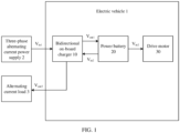
- FIG. 1 is a diagram of a structure of an electric vehicle according to this application.
- the electric vehicle 1 includes a bidirectional on-board charger 10, a power battery 20, and a drive motor 30.
- the bidirectional on-board charger 10 is configured to receive an input voltage V in1 provided by a three-phase alternating current power supply 2, and provide an output voltage V out1 to supply power to the power battery 20.
- the power battery 20 is configured to provide an input voltage V in2 to the drive motor 30 to supply power to the drive motor 30.
- the three-phase alternating current power supply 2 may be an alternating current power grid, an alternating current charging pile, or an uninterruptible power supply (uninterruptible power system, UPS).
- UPS uninterruptible power system
- the bidirectional on-board charger 10 is further configured to receive the input voltage V in2 provided by the power battery 20, and provide an output voltage V out2 to supply power to an alternating current load 3.
- the alternating current load 3 is disposed inside the electric vehicle 1.
- the alternating current load 3 may be a compressor motor or another low-power motor.
- the alternating current load 3 is disposed outside the electric vehicle 1.
- the alternating current load 3 may be a mobile phone, a tablet computer, a notebook computer, a Bluetooth headset, a lamp, an induction cooker, a kettle, a game console, a power bank, or an intelligent wearable device.
- the three-phase alternating current power supply 11 may be an alternating current power grid, an alternating current charging pile, or an uninterruptible power supply (uninterruptible power system, UPS).
- the alternating current load 13 may be a compressor motor, another low-power motor, a mobile phone, a tablet computer, a notebook computer, a Bluetooth headset, a lamp, an induction cooker, a kettle, a game console, a power bank, or an intelligent wearable device.
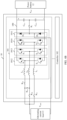
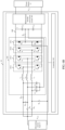
- the three second bridge arms include a second bridge arm 1012, a second bridge arm 1013, and a second bridge arm 1014, which are separately connected in series between the positive electrode and the negative electrode of the direct current bus 100.
- a midpoint of at least one of the second bridge arms is configured to receive the single-phase alternating current V in3
- midpoints of the second bridge arm 1012, the second bridge arm 1013, and the second bridge arm 1014 are configured to receive the three-phase alternating current V in4
- at least one of the second bridge arms is configured to receive the direct current V in5 .
- the controller 102 may be a control board, a control chip, or software code.
- the controller 102 may establish wired connections or wireless connections with the first switch K 1 and the power factor correction circuit 101.
- the controller 102 is configured to control turn-on or turn-off of the first switch K 1 , and control running of the power factor correction circuit 101.
- the controller 102 is configured to control actions of each second bridge arm in the second bridge arm 1012, the second bridge arm 1013, and the second bridge arm 1014, to control running of the power factor correction circuit 101.
- the controller 102 is configured to:
- the controller 102 provided in this application is configured to control the first switch K 1 , the second bridge arm 1012, the second bridge arm 1013, and the second bridge arm 1014 to cooperate with each other, so that the bidirectional on-board charger 10 is compatible with a forward charging function of charging the power battery 12 and a reverse discharging function of supplying power to the alternating current load 13, thereby greatly reducing circuit costs. Therefore, operational flexibility is high, and applicability is high.
- the positive bus capacitor C dc1 or the negative bus capacitor C dc2 , the first switch K 1 , the first bridge arm 1011, the second bridge arm 1012, the second bridge arm 1013, and the second bridge arm 1014 may form a reverse direct current (direct current, DC)/alternating current (alternating current, AC) circuit, which is configured to implement the reverse discharging function of supplying power to the alternating current load 13.
- the first bridge arm 1011 includes a diode D 1 and a diode D 2 connected in series, and a series connection point of the diode D 1 and the diode D 2 serves as the midpoint of the first bridge arm 1011, and therefore costs of the bridge arm are lower.
- the first bridge arm 1011 includes two switches connected in series, and a series connection point of the two switches serves as the midpoint of the first bridge arm 1011.
- the second switch and the third switch in each second bridge arm are complementarily turned on.
- the third switch is turned off when the second switch is turned on, or the third switch is turned on when the second switch is turned off.
- the one time period and the another time period are within one switching period of the second bridge arm, and the another time period is after the one time period.
- Three live wires of the three-phase alternating current power supply 11 are respectively led out from the alternating current potential V ga , the alternating current potential V gb , and the alternating current potential V gc , and a neutral wire of the three-phase alternating current power supply 11 is led out from a neutral point of the alternating current potential V ga , the alternating current potential V gb , and the alternating current potential V gc .
- the neutral wire may also be referred to as an N wire.
- the three fourth switches include a fourth switch K 2a , a fourth switch K 2b , and a fourth switch K 2c .
- the midpoint of the second bridge arm 1012 is connected to the first connection terminal of the alternating current load 13 through the fourth switch K 2a
- the midpoint of the second bridge arm 1013 is connected to the first connection terminal of the alternating current load 13 through the fourth switch K 2b
- the midpoint of the second bridge arm 1014 is connected to the first connection terminal of the alternating current load 13 through the fourth switch K 2c .
- the controller 102 is configured to: control any one of the fourth switches to be turned on, and control the other two of the fourth switches to be turned off, so that the midpoint of the at least one of the second bridge arms receives the single-phase alternating current V in3 or outputs the alternating current V out4 ; or control the fourth switch K 2a , the fourth switch K 2b , and the fourth switch K 2c to be turned on, so that the midpoints of the second bridge arm 1012, the second bridge arm 1013, and the second bridge arm 1014 receive the three-phase alternating current V in4 .
- the controller 102 is configured to control any fourth switch or all fourth switches in the fourth switch K 2a , the fourth switch K 2b , and the fourth switch K 2c to be turned on, so that the midpoint of the second bridge arm may receive the single-phase alternating current V in3 , or receive the three-phase alternating current V in4 , or output the alternating current V out4 , thereby meeting different working requirements of the bidirectional on-board charger 10. Therefore, operational flexibility is high.
- the any one of the fourth switches is the fourth switch K 2a
- the second bridge arm corresponding to the any one of the fourth switches is the second bridge arm 1012
- the other two of the second bridge arms are the second bridge arm 1013 and the second bridge arm 1014
- the any one of the other two of the second bridge arms is the second bridge arm 1013.
- the midpoint of the second bridge arm 1013 is connected to a first connection end of the fourth switch K 2a through the fifth switch K 3a
- the first connection end of the fourth switch K 2a is connected to the live wire led out of the alternating current potential V ga .
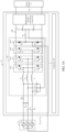
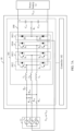
- FIG. 4B is a schematic of another circuit of a bidirectional on-board charger according to this application.
- the bidirectional on-board charger 10 includes one fifth switch K 3a
- the second bridge arm 1012, the second bridge arm 1013, and the second bridge arm 1014 include the other two of the second bridge arms other than a second bridge arm corresponding to the any one of the fourth switches.
- a midpoint of any one of the other two of the second bridge arms is connected to a first connection end of the any one of the fourth switches through the fifth switch K 3a
- the first connection end of the any one of the fourth switches is connected to the first connection terminal of the alternating current load 13.
- the any one of the fourth switches is the fourth switch K 2a
- the second bridge arm corresponding to the any one of the fourth switches is the second bridge arm 1012
- the other two of the second bridge arms are the second bridge arm 1013 and the second bridge arm 1014
- the any one of the other two of the second bridge arms is the second bridge arm 1013.
- the midpoint of the second bridge arm 1013 is connected to a first connection end of the fourth switch K 2a through the fifth switch K 3a
- the first connection end of the fourth switch K 2a is connected to the first connection terminal of the alternating current load 13.
- the controller 102 provided in this embodiment of this application may establish wired connections or wireless connections with the fourth switch K 2a , the fourth switch K 2b , the fourth switch K 2c , and the fifth switch K 3a .
- the controller 102 is configured to control the fourth switch K 2a , the fourth switch K 2b , the fourth switch K 2c , and the fifth switch K 3a to be turned on or turned off, so that the power factor correction circuit 101 receives the single-phase alternating current V in3 , or receives the three-phase alternating current V in4 , or outputs the alternating current V out4 .
- the power factor correction circuit 101 configured to receive the single-phase alternating current V in3 or output the alternating current V out4 .
- the controller 102 is configured to: control the fourth switch K 2a and the fifth switch K 3a to be turned on, and control the other two of the fourth switches to be turned off, so that the midpoint of the at least one of the second bridge arms receives the single-phase alternating current V in3 or outputs the alternating current V out4 , where the other two of the fourth switches are the fourth switch K 2b and the fourth switch K 2c , and the at least one of the second bridge arms includes the second bridge arm 1012 and the second bridge arm 1013; or control the fourth switch K 2a , the fourth switch K 2b , and the fourth switch K 2c to be turned off, and control the fifth switch K 3a to be turned on, so that the midpoint of the at least one of the second bridge arms receives the single-phase alternating current V in3 or outputs the alternating current V out4 , where the at least one of
- the controller 102 is configured to control each switch in the fourth switch K 2a , the fourth switch K 2b , the fourth switch K 2c , and the fifth switch K 3a to be turned on or turned off, so that the midpoint of the second bridge arm may receive the single-phase alternating current V in3 or output the alternating current V out4 , thereby meeting different working requirements of the bidirectional on-board charger 10. Therefore, operational flexibility is high.
- the power factor correction circuit 101 provided in this embodiment of this application is configured to receive the three-phase alternating current V in4 .
- the controller 102 is configured to: control the fourth switch K 2a , the fourth switch K 2b , and the fourth switch K 2c to be turned on, and control the fifth switch K 3a to be turned off, so that the midpoints of the second bridge arm 1012, the second bridge arm 1013, and the second bridge arm 1014 receive the three-phase alternating current V in4 .
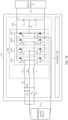
- FIG. 5A is a schematic of another circuit of a bidirectional on-board charger according to this application.
- the power factor correction circuit 101 includes three filter capacitors corresponding to the filter inductor L a , the filter inductor L b , and the filter inductor L c , and the three filter capacitors include a filter capacitor C a , a filter capacitor C b , and a filter capacitor C c .
- the filter inductor L a is connected to a first connection end of the filter capacitor C a
- the filter inductor L b is connected to a first connection end of the filter capacitor C b
- the filter inductor L c is connected to a first connection end of the filter capacitor C c .
- a second connection end of each filter capacitor in the filter capacitor C a , the filter capacitor C b , and the filter capacitor C c is connected to the series connection point of the positive bus capacitor C dc1 and the negative bus capacitor C dc2 .
- the bidirectional on-board charger 10 includes a bidirectional DC/DC conversion circuit 103, and the bidirectional DC/DC conversion circuit 103 is connected in series between the positive electrode and the negative electrode of the direct current bus 100. It should be noted that, for a connection relationship between other devices in the bidirectional on-board charger 10, refer to the embodiment corresponding to FIG. 4A . Details are not described herein again.
- the filter inductor L a , the filter inductor L b , the filter inductor L c , the filter capacitor C a , the filter capacitor C b , and the filter capacitor C c may form a filter circuit, and the first bridge arm 1011, the second bridge arm 1012, the second bridge arm 1013, and the second bridge arm 1014 may form a bridge arm conversion circuit.
- the bidirectional on-board charger 10 provided in this embodiment of this application is configured to charge the power battery 12 by using the three-phase alternating current power supply 11.
- the filter circuit is configured to filter the single-phase alternating current V in3 or the three-phase alternating current V in4 provided by the three-phase alternating current power supply 11, and output the direct current V out3 through the bridge arm conversion circuit to charge the power battery 12, thereby reducing switching ripples of the bidirectional on-board charger 10. Therefore, applicability is high.
- the bidirectional DC/DC conversion circuit 103 is configured to receive an output voltage of the bridge arm conversion circuit, and output the direct current V out3 to charge the power battery 12.
- FIG. 5B is a schematic of another circuit of a bidirectional on-board charger according to this application.
- the power factor correction circuit 101 provided in this embodiment of this application is configured to supply power to the alternating current load 13 by using the power battery 12.
- the bridge arm conversion circuit is configured to: receive the direct current V in5 provided by the power battery 12 or a direct current output by the power battery 12 through the bidirectional DC/DC conversion circuit 103, and output the alternating current V out4 after being filtered by the filter circuit to supply power to the alternating current load 13, thereby reducing switching ripples of the bidirectional on-board charger 10. Therefore, applicability is high.
- the bidirectional on-board charger 10 provided in this embodiment of this application is configured to supply power to the alternating current load 13 by using the power battery 12.
- the controller 102 is configured to control the sixth switch K 4 to be turned on.
- a current output by the positive end of the power battery 12 sequentially flows through the positive bus capacitor C dc1 , the first switch K 1 , the sixth switch K 4 , and the third switch S 6 and returns to the negative end of the power battery 12 to form a balancing circuit, and the balancing circuit is configured to balance the voltage of the positive bus capacitor C dc1 and the voltage of the negative bus capacitor C dc2 .
- a specific turn-on duration of the third switch S 6 may be determined based on the difference, and the difference is a value obtained by subtracting the voltage of the positive bus capacitor C dc1 from the voltage of the negative bus capacitor C dc2 .
- the second threshold is a threshold specified by a user or a threshold configured by the controller 102. In an embodiment, the first threshold and the second threshold may be the same or may be different.
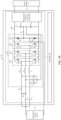
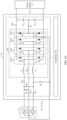
- FIG. 7A is a schematic of another circuit of a bidirectional on-board charger according to this application.
- the second bridge arm 1012, the second bridge arm 1013, and the second bridge arm 1014 include the other two of the second bridge arms other than a second bridge arm corresponding to the any one of the fourth switches
- the bidirectional on-board charger 10 includes two fifth switches corresponding to the other two of the second bridge arms
- the two fifth switches include a fifth switch K 3a and a fifth switch K 3b .
- a midpoint of any one of the other two of the second bridge arms is connected to a first connection end of the any one of the fourth switches through a fifth switch corresponding to the second bridge arm, and the first connection end of the any one of the fourth switches is connected to one live wire of the three-phase alternating current power supply 11.
- the any one of the fourth switches is the fourth switch K 2a
- the second bridge arm corresponding to the any one of the fourth switches is the second bridge arm 1012
- the other two of the second bridge arms are the second bridge arm 1013 and the second bridge arm 1014.
- the midpoint of the second bridge arm 1013 is connected to a first connection end of the fourth switch K 2a through the fifth switch K 3a corresponding to the second bridge arm 1013
- the midpoint of the second bridge arm 1014 is connected to the first connection end of the fourth switch K 2a through the fifth switch K 3b corresponding to the second bridge arm 1014
- the first connection end of the fourth switch K 2a is connected to the live wire led out of the alternating current potential V ga .
- FIG. 7B is a schematic of another circuit of a bidirectional on-board charger according to this application.
- the second bridge arm 1012, the second bridge arm 1013, and the second bridge arm 1014 include the other two of the second bridge arms other than a second bridge arm corresponding to the any one of the fourth switches, and the bidirectional on-board charger 10 shown in FIG. 3B further includes a fifth switch K 3a and a fifth switch K 3b that correspond to the other two of the second bridge arms.
- a midpoint of any one of the other two of the second bridge arms is connected to a first connection end of the any one of the fourth switches through a fifth switch corresponding to the second bridge arm, and the first connection end of the any one of the fourth switches is connected to the first connection terminal of the alternating current load 13.
- the any one of the fourth switches may be the fourth switch K 2a , the second bridge arm corresponding to the any one of the fourth switches is the second bridge arm 1012, and the other two of the second bridge arms are the second bridge arm 1013 and the second bridge arm 1014.
- the midpoint of the second bridge arm 1013 is connected to a first connection end of the fourth switch K 2a through the fifth switch K 3a corresponding to the second bridge arm 1013
- the midpoint of the second bridge arm 1014 is connected to the first connection end of the fourth switch K 2a through the fifth switch K 3b corresponding to the second bridge arm 1014
- the first connection end of the fourth switch K 2a is connected to the first connection terminal of the alternating current load 13.
- the controller 102 may establish wired connections or wireless connections with the fourth switch K 2a , the fourth switch K 2b , the fourth switch K 2c , the fifth switch K 3a , and the fifth switch K 3b .
- the controller 102 is configured to control the fourth switch K 2a , the fourth switch K 2b , the fourth switch K 2c , the fifth switch K 3a , and the fifth switch K 3b to be turned on or turned off, so that the power factor correction circuit 101 receives the single-phase alternating current V in3 , or receives the three-phase alternating current V in4 , or outputs the alternating current V out4 .
- the power factor correction circuit 101 configured to receive the single-phase alternating current V in3 or output the alternating current V out4 .
- the controller 102 is configured to: control the fourth switch K 2a , the fifth switch K 3a , and the fifth switch K 3b to be turned on, and control other two of the fourth switches to be turned off, so that the midpoint of the at least one of the second bridge arms receives the single-phase alternating current V in3 or outputs the alternating current V out4 , where the other two of the fourth switches are the fourth switch K 2b and the fourth switch K 2c , and the at least one of the second bridge arms includes the second bridge arm 1012, the second bridge arm 1013, and the second bridge arm 1014; or control the fourth switch K 2a , the fourth switch K 2b , and the fourth switch K 2c to be turned off, and control the fifth switch K 3a and the fifth switch K 3b to be turned on, so that the midpoint of the at least one of the second bridge arms receives the single-phase
- the controller 102 is configured to control each switch in the fourth switch K 2a , the fourth switch K 2b , the fourth switch K 2c , the fifth switch K 3a , and the fifth switch K 3b to be turned on or turned off, so that the midpoint of the second bridge arm receives the single-phase alternating current V in3 or outputs the alternating current V out4 , thereby meeting different working requirements of the bidirectional on-board charger 10. Therefore, operational flexibility is high.
- the power factor correction circuit 101 provided in this embodiment of this application is configured to receive the three-phase alternating current V in4 .
- the controller 102 is configured to: control the fourth switch K 2a , the fourth switch K 2b , and the fourth switch K 2c to be turned on, and control the fifth switch K 3a and the fifth switch K 3b to be turned off, so that the midpoints of the second bridge arm 1012, the second bridge arm 1013, and the second bridge arm 1014 receive the three-phase alternating current V in4 .
- FIG. 8A is a schematic of another circuit of a bidirectional on-board charger according to this application.
- the bidirectional on-board charger 10 includes a sixth switch K 4 , and the midpoint of the second bridge arm 1014 is connected to the neutral wire of the three-phase alternating current power supply 11 through the filter inductor L c and the sixth switch K 4 .
- the midpoint of the second bridge arm 1014 is connected to the neutral wire of the three-phase alternating current power supply 11 through the filter inductor L c and the sixth switch K 4 .
- FIG. 8B is a schematic of another circuit of a bidirectional on-board charger according to this application.
- the bidirectional on-board charger 10 includes a sixth switch K 4 , and the midpoint of the second bridge arm 1014 is connected to a second connection terminal of the alternating current load 13 through the filter inductor L c and the sixth switch K 4 .
- the midpoint of the second bridge arm 1014 is connected to a second connection terminal of the alternating current load 13 through the filter inductor L c and the sixth switch K 4 .
- the bidirectional on-board charger 10 provided in this embodiment of this application is configured to supply power to the alternating current load 13 by using the power battery 12.
- the controller 102 is configured to control the fifth switch K 3a and the sixth switch K 4 to be turned on, and control the fifth switch K 3b to be turned off.
- the second bridge arm 1014 may be a balancing bridge arm of the positive bus capacitor C dc1 and the negative bus capacitor C dc2 , and the balancing bridge arm is configured to balance a voltage of the positive bus capacitor C dc1 and a voltage of the negative bus capacitor C dc2 .
- the balancing bridge arm For a specific working principle of the balancing bridge arm, refer to the embodiment corresponding to FIG. 6B . Details are not described herein again.
- the single-phase alternating current V in3 or the three-phase alternating current V in4 provided by the three-phase alternating current power supply 11 may be used for charging the power battery 12, or the direct current V in5 provided by the power battery 12 may be used for supplying power to the alternating current load 13, so that the bidirectional on-board charger 10 is compatible with a forward charging function and a reverse discharging function of single-phase and three-phase inputs, thereby greatly reducing circuit costs. Therefore, operational flexibility is high, and applicability is high.
- FIG. 9 is a diagram of a structure of an EV power trend system according to this application.
- the EV power trend system 4 includes a power battery 40 and a bidirectional on-board charger 41, and the bidirectional on-board charger 41 is configured to charge the power battery 40.
- the bidirectional on-board charger 41 is compatible with a forward charging function and a reverse discharging function of single-phase and three-phase inputs. Therefore, this may improve working efficiency of the EV power trend system 4, and greatly reduce circuit costs of the EV power trend system 4, and applicability is high.
Landscapes
- Engineering & Computer Science (AREA)
- Power Engineering (AREA)
- Transportation (AREA)
- Mechanical Engineering (AREA)
- Charge And Discharge Circuits For Batteries Or The Like (AREA)
Applications Claiming Priority (2)
| Application Number | Priority Date | Filing Date | Title |
|---|---|---|---|
| CN202210782895.3A CN115230506B (zh) | 2022-07-05 | 2022-07-05 | 双向车载充电机、车载动力系统及电动车辆 |
| PCT/CN2023/089927 WO2024007688A1 (fr) | 2022-07-05 | 2023-04-21 | Chargeur embarqué bidirectionnel, système d'alimentation embarqué et véhicule électrique |
Publications (2)
| Publication Number | Publication Date |
|---|---|
| EP4538106A1 true EP4538106A1 (fr) | 2025-04-16 |
| EP4538106A4 EP4538106A4 (fr) | 2025-12-10 |
Family
ID=83670922
Family Applications (1)
| Application Number | Title | Priority Date | Filing Date |
|---|---|---|---|
| EP23834467.5A Pending EP4538106A4 (fr) | 2022-07-05 | 2023-04-21 | Chargeur embarqué bidirectionnel, système d'alimentation embarqué et véhicule électrique |
Country Status (4)
| Country | Link |
|---|---|
| US (1) | US20250135928A1 (fr) |
| EP (1) | EP4538106A4 (fr) |
| CN (1) | CN115230506B (fr) |
| WO (1) | WO2024007688A1 (fr) |
Families Citing this family (4)
| Publication number | Priority date | Publication date | Assignee | Title |
|---|---|---|---|---|
| CN115230506B (zh) * | 2022-07-05 | 2025-04-01 | 华为数字能源技术有限公司 | 双向车载充电机、车载动力系统及电动车辆 |
| CN117104041B (zh) * | 2023-08-23 | 2024-05-28 | 上汽通用五菱汽车股份有限公司 | 一种适用于电动汽车的车载充电电路及车辆 |
| CN119705068A (zh) * | 2024-12-05 | 2025-03-28 | 浙江吉利控股集团有限公司 | 车辆按摩座椅驱动系统和车辆 |
| CN119428191A (zh) * | 2024-12-05 | 2025-02-14 | 浙江吉利控股集团有限公司 | 车辆空气悬挂系统和车辆 |
Family Cites Families (13)
| Publication number | Priority date | Publication date | Assignee | Title |
|---|---|---|---|---|
| JPH08317638A (ja) * | 1995-05-22 | 1996-11-29 | Hitachi Ltd | 電力変換装置 |
| US20160172992A1 (en) * | 2014-12-16 | 2016-06-16 | Rockwell Automation Technologies, Inc. | Ac drive scr and relay precharging apparatus |
| CN105406747B (zh) * | 2015-12-25 | 2018-03-20 | 成都麦隆电气有限公司 | 一种npc三电平内管无损均压钳位电路 |
| DE102018208264B4 (de) * | 2018-05-25 | 2024-12-05 | Vitesco Technologies GmbH | Konfigurierbare Wechselstrom-Ladevorrichtung |
| CN109861357A (zh) * | 2018-09-07 | 2019-06-07 | 台达电子工业股份有限公司 | 充放电方法与装置 |
| CN109889077B (zh) * | 2019-04-08 | 2021-01-26 | 台达电子企业管理(上海)有限公司 | 单相和三相兼容的ac/dc电路及充放电装置 |
| CN210075077U (zh) * | 2019-06-14 | 2020-02-14 | 苏州汇川联合动力系统有限公司 | 一种功率因数校正电路及车载充电机 |
| CN110356268B (zh) * | 2019-06-25 | 2021-08-03 | 华为技术有限公司 | 一种车载充放电装置和系统 |
| CN110460140B (zh) * | 2019-09-23 | 2026-04-10 | 台达电子企业管理(上海)有限公司 | 车载充放电系统 |
| DE102019215306B4 (de) * | 2019-10-07 | 2022-06-30 | Vitesco Technologies GmbH | Zwischenkreisschaltung und fahrzeugseitige Ladeschaltung mit Zwischenkreisschaltung |
| CN111355287B (zh) * | 2020-03-23 | 2022-04-08 | 台达电子企业管理(上海)有限公司 | 车载充电机 |
| CN111371103A (zh) * | 2020-04-29 | 2020-07-03 | 广西电网有限责任公司钦州供电局 | 一种带零序均压桥臂的电容分裂式静止补偿器电路及方法 |
| CN115230506B (zh) * | 2022-07-05 | 2025-04-01 | 华为数字能源技术有限公司 | 双向车载充电机、车载动力系统及电动车辆 |
-
2022
- 2022-07-05 CN CN202210782895.3A patent/CN115230506B/zh active Active
-
2023
- 2023-04-21 EP EP23834467.5A patent/EP4538106A4/fr active Pending
- 2023-04-21 WO PCT/CN2023/089927 patent/WO2024007688A1/fr not_active Ceased
-
2025
- 2025-01-03 US US19/009,777 patent/US20250135928A1/en active Pending
Also Published As
| Publication number | Publication date |
|---|---|
| CN115230506A (zh) | 2022-10-25 |
| CN115230506B (zh) | 2025-04-01 |
| EP4538106A4 (fr) | 2025-12-10 |
| US20250135928A1 (en) | 2025-05-01 |
| WO2024007688A1 (fr) | 2024-01-11 |
Similar Documents
| Publication | Publication Date | Title |
|---|---|---|
| EP4538106A1 (fr) | Chargeur embarqué bidirectionnel, système d'alimentation embarqué et véhicule électrique | |
| EP3886304B1 (fr) | Chargeur embarqué | |
| EP4527681A1 (fr) | Chargeur embarqué, système d'alimentation embarqué et véhicule électrique | |
| EP3790155A1 (fr) | Système de charge et de décharge embarqué | |
| EP3922504A1 (fr) | Appareil de charge/décharge monté sur véhicule et système | |
| EP2903125B1 (fr) | Alimentation sans coupure (ups) et son circuit continu-continu | |
| CN202221964U (zh) | 功率转换器系统 | |
| EP2709236B1 (fr) | Circuit d'alimentation électrique ininterrompue et procédé de commande | |
| CN1284777A (zh) | 包括平衡器电路的多方式功率变换器及其操作方法 | |
| CN103647483A (zh) | 一种集成开关磁阻电机驱动和电池充电的功率变换装置 | |
| CN104734264A (zh) | 在线互动式不间断电源及其控制方法 | |
| CN203708154U (zh) | 一种集成开关磁阻电机驱动和电池充电的功率变换装置 | |
| US12451801B2 (en) | DC/DC converter, voltage gain switching method and system | |
| EP4068610B1 (fr) | Convertisseur et chargeur embarqué | |
| EP4054067A1 (fr) | Module de régulation de tension, module de charge et pile de charge | |
| EP4696547A1 (fr) | Dispositif de charge | |
| EP3975411B1 (fr) | Redresseur, système chargeur et véhicule électrique | |
| EP4250550A1 (fr) | Onduleur clampé par le point neutre et système d'alimentation électrique photovoltaïque | |
| CN203691365U (zh) | 功率半导体开关驱动电路的自供电电路 | |
| EP3312980A1 (fr) | Amortisseur et dispositif de conversion d'énergie électrique l'utilisant | |
| KR20110063186A (ko) | 양방향 전력제어 방식의 배터리 충전장치 | |
| CN210350838U (zh) | 车载充放电系统 | |
| CN223797964U (zh) | 三相不间断电源系统 | |
| EP4462662A1 (fr) | Module d'alimentation électrique, circuit de commande et dispositif électronique | |
| KR100831647B1 (ko) | 2 개의 전력 반도체 스위치를 이용한 pwm 부스트-벅ac-ac 전력 변환기 |
Legal Events
| Date | Code | Title | Description |
|---|---|---|---|
| STAA | Information on the status of an ep patent application or granted ep patent |
Free format text: STATUS: THE INTERNATIONAL PUBLICATION HAS BEEN MADE |
|
| PUAI | Public reference made under article 153(3) epc to a published international application that has entered the european phase |
Free format text: ORIGINAL CODE: 0009012 |
|
| STAA | Information on the status of an ep patent application or granted ep patent |
Free format text: STATUS: REQUEST FOR EXAMINATION WAS MADE |
|
| 17P | Request for examination filed |
Effective date: 20250110 |
|
| AK | Designated contracting states |
Kind code of ref document: A1 Designated state(s): AL AT BE BG CH CY CZ DE DK EE ES FI FR GB GR HR HU IE IS IT LI LT LU LV MC ME MK MT NL NO PL PT RO RS SE SI SK SM TR |
|
| DAV | Request for validation of the european patent (deleted) | ||
| DAX | Request for extension of the european patent (deleted) | ||
| A4 | Supplementary search report drawn up and despatched |
Effective date: 20251111 |
|
| RIC1 | Information provided on ipc code assigned before grant |
Ipc: B60L 53/22 20190101AFI20251105BHEP Ipc: H02J 7/02 20160101ALI20251105BHEP |