EP4538218A1 - Vorrichtung zur handhabung einer schnittstelle eines behälters, insbesondere eines kippbehälters - Google Patents
Vorrichtung zur handhabung einer schnittstelle eines behälters, insbesondere eines kippbehälters Download PDFInfo
- Publication number
- EP4538218A1 EP4538218A1 EP24205710.7A EP24205710A EP4538218A1 EP 4538218 A1 EP4538218 A1 EP 4538218A1 EP 24205710 A EP24205710 A EP 24205710A EP 4538218 A1 EP4538218 A1 EP 4538218A1
- Authority
- EP
- European Patent Office
- Prior art keywords
- container
- interface device
- interface
- forklift
- intended
- Prior art date
- Legal status (The legal status is an assumption and is not a legal conclusion. Google has not performed a legal analysis and makes no representation as to the accuracy of the status listed.)
- Withdrawn
Links
Images





Classifications
-
- B—PERFORMING OPERATIONS; TRANSPORTING
- B66—HOISTING; LIFTING; HAULING
- B66F—HOISTING, LIFTING, HAULING OR PUSHING, NOT OTHERWISE PROVIDED FOR, e.g. DEVICES WHICH APPLY A LIFTING OR PUSHING FORCE DIRECTLY TO THE SURFACE OF A LOAD
- B66F9/00—Devices for lifting or lowering bulky or heavy goods for loading or unloading purposes
- B66F9/06—Devices for lifting or lowering bulky or heavy goods for loading or unloading purposes movable, with their loads, on wheels or the like, e.g. fork-lift trucks
- B66F9/075—Constructional features or details
- B66F9/12—Platforms; Forks; Other load supporting or gripping members
- B66F9/19—Additional means for facilitating unloading
-
- B—PERFORMING OPERATIONS; TRANSPORTING
- B65—CONVEYING; PACKING; STORING; HANDLING THIN OR FILAMENTARY MATERIAL
- B65F—GATHERING OR REMOVAL OF DOMESTIC OR LIKE REFUSE
- B65F1/00—Refuse receptacles; Accessories therefor
- B65F1/14—Other constructional features; Accessories
- B65F1/1452—Lifting, hoisting, elevating mechanisms or the like for refuse receptacles
Definitions
- the invention relates to the field of handling containers, in particular tilting containers intended for the temporary storage of any type of object or waste.
- the invention will be more particularly described with regard to the handling of tilting containers with a view to their tipping into a storage bin, without however being limited thereto, and may be applied to any container to be handled by a forklift.
- a standard tipping container to be handled with a forklift truck comprises a chassis with a pair of sleeves for the passage of the forks of a forklift truck, a box fixed on the chassis and pivoted to move from an upright and horizontal position for storing waste to a tilted position for dumping waste by gravity, and a locking and unlocking system for the box in the upright position.
- the locking system is manually operated by the operator to unlock the box lock and allow it to tip.
- such a container has the disadvantage of requiring an operator to manually operate the locking system to dump the box and then manually relock the box once emptied and returned to the upright position. The operator is often the forklift driver who must therefore get off the forklift truck and then get back on several times.
- the patent application FR2958924 proposes a removable interface device between the forklift and the tilting container; this interface device comprises passages for the forks of a forklift, which are intended to be inserted into the sleeves of the container chassis, and an automated system for lifting one of the ends of the container allowing the box to be pivoted.
- the automated lifting system comprises a central column with a slide capable of tilting via a jack, and a pair of miniature arms close together cooperating in vertical translation in the slide of the central column to be positioned at the height of the box.
- the pair of arms, opposite the slide cooperates centrally with the edge of the box and the pivoting of the slide causes the box to tilt.
- This interface device makes it possible to move from one container to another with a forklift and to tilt the container in an automated manner.
- the small vehicle allows the container to be lifted to the edge of the skip, which is then able to be moved along the skip tracks to be dumped at a distance from the edge of the skip.
- This advantageous solution allows the entire volume of the skip to be filled gradually by placing the small vehicle always at the end of the skip, without having to move around it. Nevertheless, the entire small vehicle and container are specifically designed. However, for certain applications, it may be desirable to continue to use a forklift as a means of transporting and lifting the container and to use existing standard containers.
- the invention therefore aims to propose a solution for an interface device for handling a tilting container above a storage bin, which can be used if necessary with a forklift and usual containers, without having the aforementioned drawbacks.
- the invention also aims to propose a solution for an interface device for handling a tilting container above a storage bin, which when the container is at the height of the bin can be emptied at different locations in the storage bin, the container being at the height of the storage bin, either because the arrival dock of the handling container is directly at the height of the upper emptying plane of the storage bin, or because the handling container is capable of being translated in height from the ground to the upper emptying plane of the storage bin by any systems lifting (forklift as a fixed structure with elevator function, installed on the ground and at the end of a storage bin).
- the handling interface device according to one embodiment is in accordance with claim 1.
- the handling interface device is intended to cooperate with a forklift and to carry a container, in particular a tilting container, and comprises a chassis provided with passages designed to accommodate forks of a forklift, support means intended to carry the container and a structure with a mobility function, intended to make the container mobile (while the interface device is intended to be carried by the forklift), the interface device being characterized in that the structure with a mobility function operates in horizontal translation so that it is capable of moving in horizontal translation the container which is intended to be carried by the interface device.
- the interface device allows a container to be carried and is entirely suitable for being transported and conveyed by a forklift to bring the container to the desired location, in particular to a storage bin, to raise it to the appropriate height, in particular to the height of the upper opening plane of the storage bin, and to move it in translation, in particular above the storage bin to dump it at the desired location in the bin.
- the handling interface device is intended to carry a container, in particular a tilting container, and comprises support means intended to carry the container and a structure with a mobility function, intended to make the container mobile, the interface device being characterized in that the structure with a mobility function operates in horizontal translation so that it is capable of moving in horizontal translation the container which is intended to be carried by the interface device.
- the interface device can carry any type of container, and be positioned at the end of a storage bin while allowing it to be filled gradually along its length thanks to the translation of the mobility structure of the interface device.
- the container is brought away from the end of the bin to be dumped at any point in the storage bin.
- the interface device does not have to be equipped with forklift pockets if it is fixed. Indeed, the interface device can be permanently fixed against a dock where a storage bin is located below; the handling container is brought to the interface device by positioning it on the support means of said interface device and once in place, the container can be translated above the storage bin away from the dock.
- the interface device comprises a rear part, a front part comprising the support means, the structure with a mobility function being intended to make the container mobile by horizontally translating the front part relative to the rear part, and in that the rear part comprises jacks connected to the rear end of the structure with a mobility function, the jacks being able to pivot the front part when the latter is in position against the rear part (non-translated position or so-called folded position) so as to raise and lower said front part, in particular to raise and lower said front part when the latter is equipped with rolling or sliding members.
- the rear part comprises complementary means of support for a container when the mobility structure is said to be folded (front part completely against the rear part), the front part being cantilevered relative to the rear part, this makes it possible to support the front part and the container in the void.
- the complementary means of support of the rear part form elongated elements in the manner of forks which cooperate with the support means of the front part, in particular which cooperate by introduction into hollow interface profiles of the support means and into the sheaths with which the container is provided when the container is in place on the device.
- the interface device also does not have to be provided with fork passages if it cooperates with another means of elevation than a forklift.
- the handling interface device is intended to carry a container, in particular a tilting container, and comprises support means intended to carry the container, a rear part, a front part comprising the support means, a structure with a mobility function, intended to make the container mobile by horizontally translating the front part relative to the rear part, the rear part constituting a seat structure of the interface device and being fixed by being intended to be installed on the ground, and the front part being arranged at a height, the interface device further comprising a lifting and lowering system intended and capable of raising and lowering the handling container between the ground and the plane where the front part capable of being translated is located.
- the lifting system constitutes or is coupled to the support means of the container and also constitutes a locking and unlocking system intended to ensure the blocking and unlocking of the tilting of the container, preferably the lifting and lowering system being a system with motorized chains and sprockets.
- the qualifiers "horizontal”, “vertical”, “upper”, “lower”, “top” and “bottom” of an element of the interface device and of a tilting container are used in the context of a normal installation of the interface device and of the tilting container, that is to say relating to a vertical notion in relation to a horizontal surface on which the interface device or the container would be placed.
- front describes an element in the context of normal use of the interface device and the tilting container, the front of the interface device corresponding to the area at which the container will be installed while the rear will be intended to cooperate with a forklift or with another means of elevation or intended to remain fixed, and the front of the container corresponding to the area from which the container will be dumped.
- the term “upright position” means the untipped position of the tilting container.
- transverse is understood to mean the direction corresponding to the width of the interface device, i.e. in the direction perpendicular to a longitudinal axis which corresponds to the front-rear direction or engagement direction of the forks of a forklift truck intended to cooperate with the interface device.
- the chassis has two parts, a so-called front and a so-called rear part, the front part comprising the means for supporting the container and the rear part comprising the fork passages, and the front part is furthermore capable of being movable in translation relative to the rear part via the structure with mobility function.
- the rear part remains carried by the forklift while the front part on which the container is installed can be moved away from the rear part and therefore away from the forklift.
- the structure with a mobility function connects the rear part to the front part and is capable of deploying and folding, preferably said structure being actuated by cylinders, in particular said structure comprising two opposite and parallel compass arms (which deploy and fold concomitantly).
- the support means are in particular two hollow interface profiles spaced apart for the passage of forks of the forklift type.
- the two hollow interface profiles are arranged in alignment with the passages designed to accommodate forks.
- the support means (intended for supporting a container) comprise two hollow and spaced interface profiles, which project towards the front of the interface device (and in a longitudinal direction which corresponds to the translation direction), the two interface profiles being, on the one hand, of the type capable of receiving the forks of a forklift, and on the other hand, capable of being introduced into a pair of sleeves which are usually used for inserting forks of a forklift (the sleeves being integral with the container intended to be carried by the interface device), preferably the two interface profiles having a generally U-shaped section.
- the interface profiles are open at least at one of their ends.
- the U-shape of the section rather than a closed right quadrilateral shape allows for material thickness to be gained on one of the faces of the profile and thus for profile height to be gained to fit with a slight clearance into a forklift fork accommodating sleeve.
- the fork passages are adjustable in spacing in an automated manner, preferably via jacks
- the support means which are in particular two hollow and spaced interface profiles for the passage of forks of a forklift, are also adjustable in spacing, preferably are able to be adjusted at the same time as the adjustment fork passages by being mechanically connected to said passages outside of any translation operation (except in the position of distance of the front part, that is to say when the front part is arranged against the rear part).
- the interface device adapts to all containers regardless of the spacing of the sheaths with which a container is equipped.
- the interface device comprises gripping means with a locking function (such as hooks) which are intended and capable of cooperating with a forklift to lock said interface device on said forklift, in particular by cooperating with (at the rear of) a rising part of the forks of the forklift, and preferably the gripping means being movable by jacks to couple and uncouple from said forklift.
- the gripping means are located at the rear of the interface device, in particular on the rear part of the two-part interface device.
- the gripping means are in particular remotely controlled for their coupling and uncoupling relative to the forklift.
- the chassis comprises a lifting system coupled to the support means and capable of lifting in vertical translation and lowering said support means, preferably the lifting system being actuated by jacks.
- This lifting system allows for certain types of containers, in particular for so-called “front axle” containers, to raise them in position above a storage bin so that when they tip and/or return to the end of the storage bin in their tilted state, they do not come up against waste present in the storage bin.
- the chassis comprises a lifting system which is integrated into the front part of the interface device and is capable of raising the handling container relative to the level of the support plane of the rolling or sliding members and lowering it into this support plane.
- the lifting system integrated into the front part may be capable of raising the handling container relative to the level of the support plane of the rolling or sliding members and lowering it into this support plane, and/or (for another embodiment) capable of lowering said handling container below the support plane of the rolling or sliding members when the mobility structure is folded and the front part is, in the installed position of the interface device, arranged outside a storage bin.
- This embodiment variant is for example used outside any forklift and when the interface device is installed in a fixed manner (third embodiment); the rear part is fixed to the ground and forms a framework in the manner of an elevator shaft for raising or lowering a container from the ground to the support plane of the rolling or sliding members.
- the lifting system constitutes (in particular in the form of suspension means) or is coupled to the support means of the container; the lifting system also constitutes a locking and unlocking system intended to ensure the blocking and unlocking of the tilting of the container.
- the interface device comprises an automated locking and unlocking interface system intended to ensure the blocking and unlocking of the tilting of a container to be positioned on the interface device
- the locking and unlocking interface system comprises a movable locking and unlocking part which is fixed to the interface device, in particular at the front of the interface device (more particularly on one of the means for supporting a container), as well as automated means for actuating the movable part and a fixed part in the form of an adaptation kit part, which is intended to be fixed on, and to be designed specifically for, a tilting actuating member with which a container intended to be carried by the interface device is provided, the movable part being able to cooperate with the fixed part in a so-called active safety position preventing the tilting of the container and in an unlocked position allowing tilting.
- a tilting container is always equipped with an actuating member such as a lever which in a certain position allows the container to tilt; this lever has a mechanical safety which when activated prevents it from being in a position allowing the container to tilt.
- the actuating member has various forms (lever, pedal, thick sheet metal, etc.), the adaptation kit part is therefore specifically designed to adapt to the actuating member.
- the kit part can be made integral with the actuating member by mechanical fixing, welding, etc.
- a standard container always has an additional mechanical safety which must be unlocked before acting on the safety directly linked to the actuating member. This additional safety guarantees in particular during movement of the container on the forklift, so that it does not tip over unexpectedly.
- the automated locking and unlocking interface system of the invention advantageously makes it possible, on the one hand, to replace the mechanical safety associated with the actuating member authorizing tipping on a tipping container, and on the other hand, to replace the additional safety.
- the fixed part of the system's adaptation kit is pre-arranged on the actuating member of the container authorizing tipping (having been designed specifically to adapt to the type of actuating member which is different depending on the manufacturer's model and whether the container is "front axle” or "central axle”).
- the mobile part which is on the interface device this is capable of being actuated in an automated manner by the operator from a human-machine interface (for example by pressing a control button visible on the interface).
- the mobile part is intended and capable of cooperating in an automated manner with the fixed part of the container's actuating member, in at least two positions, a so-called active safety position which prohibits any actuation of the actuating member (and therefore prevents any untimely tilting of the container, particularly during transport) and corresponds to the additional mechanical safety of a standard container, and an unlocked position which allows the container to be tilted.
- the operator can act on the active safety of the container in an automated manner while remaining seated in the forklift and without having to operate manually, which is a guarantee of safety for the operator.
- the mobile part of the locking and unlocking interface system is in the active position.
- the operator automatically operates the movable part to move from the active safety position to the unlocked position.
- the actuating member can be operated at the desired time to tip the container.
- the container When the container has been emptied, it will be tilted back by itself as usual by its abutment against the edge of the storage bin to put itself in the upright position and the actuating member will systematically return to its position before actuation; the operator will then be able to automatically via the human-machine interface (without getting off the trolley) operate the moving part so that it returns to the active safety position.
- the container is capable of being in a tilted position, while the mobility structure is in operation to translate the container.
- emptying is done dynamically, the inclination of the container, coupled with a translational movement, makes it possible to produce layers of waste of homogeneous thickness over the entire length of the storage bin, guaranteeing a high filling rate since there is no longer any accumulation of heterogeneous piles of waste.
- the fixed part of the kit comprises a light and the mobile part comprises a rotary cam actuated by a jack and, at the end of the cam, a hook which is capable of cooperating with the light of the fixed part, the hook being arranged parallel to the general plane of the light in the unlocked position and being arranged in the light and at an angle non-parallel to the general plane of the light in the active safety position, the cam being further capable of positioning the hook outside the light (so-called open position) to ensure the installation of the container on the support means of the interface device (without the mobile part being engaged in the light of the fixed part).
- the interface device comprises display means such as a camera and/or a scanner as well as at least one equipment block comprising the power supply, means for controlling different actuators integrated into the interface device, data processing means which receive data from the display means as well as remote communication means for remotely controlling the actuators and remotely transmitting the data from the display means.
- the interface device comprises, in particular in a rear part, at least one equipment block comprising the power supply, means for controlling the various actuators (in particular cylinders) of the interface device, data processing means which receive data from display means placed on the interface device and remote communication means for remotely controlling the actuators, as well as a human-machine interface which is intended to be arranged in the forklift, this interface being able to be nomadic.
- the communication is carried out using secure wireless technology.
- the interface device is used for at least a waste storage bin, in particular for several storage bins arranged juxtaposed against each other, the interface device being brought to the end of each of the bins.
- This makes it possible to reduce the arrangement areas of the storage bins by arranging them side by side parallel to their longitudinal direction.
- the interface device of the invention makes it possible to increase the waste storage volume by 40%: it makes it possible to position the bins side by side by eliminating the wasted space between the bins, leading to an increase of more than 30% in the bins on the ground; it makes it possible (by its mobility above a bin) to optimize the filling rate of the bins to reach a rate of 90%.
- the invention also relates to an assembly comprising a aforementioned interface device of the invention and a container, in particular a tilting container, preferably the container comprising two spaced-apart sleeves for inserting forks of a forklift.
- the invention also relates to the aforementioned assembly of the invention and at least one storage bin provided with longitudinal tracks with which the interface device cooperates for its translational movement when the structure with mobility function has been actuated.
- longitudinal tracks is meant the upper edge of the free end of the two longitudinal sides of a conventional storage bin or specific guidance equipment added to the upper edge of the free end of the two longitudinal sides of a storage bin.
- the upper end edge of the two longitudinal sides of a storage bin serves as a support for rolling the front part and the handling container.
- the interface device with the container can advantageously be moved reliably away from the distal end/edge of the bin to dump the container into a location of the bin that is still empty while the operator with his forklift remains positioned at the end of the bin. Moving the interface device and therefore the container in relation to the storage bin makes it possible to optimize the filling of the bin.
- the interface device comprises rolling or sliding members which are arranged on the front part of the chassis. These rolling or sliding members thus facilitate the guidance and translation of the interface device by their support on the upper ends of the longitudinal sides of a storage bin, when the device is simultaneously deployed in horizontal translation to advance above said storage bin.
- the front part of the device chassis has two side members two side profiles which each comprise the rolling or sliding members, preferably each side profile comprises at least two rolling or sliding members, each of the members being arranged at each end of the side profile.
- each rolling member has the shape of a cylindrical rotating roller or wheel which has an axis of rotation perpendicular to the longitudinal direction of the lateral profiles. This type of rolling member makes it possible to cooperate with the upper end edge of a conventional storage bin.
- Each rolling or sliding member is not powered.
- Each rolling or sliding member is mechanically independent of any motorized means or rack or cylinder advancement, which simplifies the interface device and does not increase manufacturing costs.
- each rolling or sliding member helps with the mobility of the front part on the storage bin during deployment and folding of the mobility structure.
- the mobility structure is preferably movable by cylinders, the interface device provides a simple overall design and limited manufacturing costs.
- each rolling or sliding member comprises a bearing surface and at least one flange extending in a plane orthogonal to the plane of the bearing surface and arranged on the outer side of the interface device (on the outer side of the lateral profile associated with the rolling or sliding member) comprising a portion projecting relative to the bearing surface and in the opposite direction of the lateral profile (i.e. downwards in the position of use of the interface device).
- the flange with its projecting portion serves as a stop surface against the outer wall of the storage bin, which contributes to the linear guidance of the rolling or sliding members.
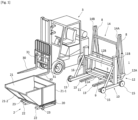
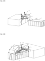
- the interface device 1 for handling and translating a container illustrated in the figures, constitutes an interface device for handling a container 2 with a forklift 3 and being able to translate it remotely from the forklift.
- the example of use of the interface device 1 of the invention is used with respect to a container 2 which is tiltable.
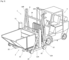
- the interface device 1 makes it possible to pour the tiltable container 2 into a storage bin 4 as illustrated in the figures 4 to 6 , at a distance from a forklift 3 which will have brought the container 2 to the end of the storage bin.
- the container 2 is intended for temporarily storing, for example, waste; it is tiltable in order to subsequently dump the waste into the bin 4 after having been raised to a height using the forklift 3 and the interface device 1.
- the bin 4 advantageously comprises longitudinal tracks or guide rails 40 arranged on the longitudinal edges of the bin 4 ( figures 4 to 7 ) in order to move in translation a part of the interface device 1 which carries the container 2 above the bucket 4, from the end where the forklift 3 is located, towards the opposite end.
- the guide tracks 40 could also be made up directly of the end edges 40' upper part of the bucket as shown in the figures 12 and following.
- Container 2 is a standard commercial container; for example, it has a central axis like the one illustrated in the Figure 1 or front axle like the one shown in the Figure 6 .
- the container 2 comprises a chassis 20, a temporary storage box 21 which has a rear part 21-1 and a front part 21-2, and two sleeves 22 spaced apart to receive the forks 30 of the forklift 3.
- the container 2 comprises a base for placing it on the ground when not being handled.
- the base may be made up of the sleeves 22 by their lower face and/or feet 23 or casters which may be retractable.
- the box 21 is capable of adopting a so-called upright position for temporary storage of the waste and a tilted position for its dumping.
- the box 21 is capable of tilting by being pivotally articulated around an axis which, in a known manner, may be said to be central or front.
- the container 2 comprises an actuating member 24 ( Figure 7 ) allowing, in its unlocked position, the container 2 to tilt.
- This actuating member 24 is located in the rear part 21-1 and is usually manually actuable. It can have various shapes depending on the manufacture (the trademark) of the container.
- the actuating member 24 is a lever.
- the interface device 1 comprises a locking and unlocking interface system 5 which is interposed between said interface device 1 and the actuating member 24 in order to remotely and automatically control the unlocking of the actuating member so that the container can be in the ready-to-tilt position.
- the interface device 1 is designed to be able to translate the container 2 horizontally beyond the edge of the bin 4 and parallel to the opening plane of the bin 4 in order to be able to dump the waste both at the end of the bin and at a distance from this end ( figures 5 And 6 ).
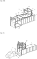
- the interface device 1 comprises a chassis 10 in two parts called the front part 11 and the rear part 12, support means 13 such as a pair of interface profiles 13 secured to the front part 11 and intended to carry the container 2, a structure with a mobility function 14, subsequently called the connecting structure, connecting the rear part 12 to the front part 11 and ensuring the translational mobility of the front part 11 of the chassis 10 relative to the rear part 12 (and therefore ensuring the mobility of the container 2 relative to the forklift 3 and the skip 4), and rolling or sliding members 15 arranged on the front part 11 of the chassis to accompany the translation of said front part 11 along the tracks 40 of the bucket 4.
- the front part 11 further comprises a lifting system 16 intended for raising the container 2 when the latter is in particular front-axled.
- the front part 11 of the chassis 10 is intended to be positioned under the container 2 ( Figure 2 ) and to support the container 2 thanks to its pair of interface profiles 13 ( Figure 1 ).
- the front part 11 comprises, for its rigidity and its functionalities, a base 11A and a gantry 11B connected by struts 11C.
- the base 11A is delimited by a so-called transverse beam 11-1, two lateral profiles 11-2 and 11-3 which extend forward perpendicular to the transverse beam 11-1.
- the side profiles 11-2 and 11-3 are fixed and the transverse beam 11-1 can be raised or lowered via the lifting system 16 along uprights 11-4 and 11-5 as described later.
- the side profiles 11-2 and 11-3 are provided on their external face with rolling or sliding members 15.
- the rolling or sliding members 15 are at the two opposite front and rear ends of the side profiles 11-2 and 11-3.
- the interface device 1 does not necessarily have a lifting system 16.
- the rolling members are not motorized; they allow rolling to guide and drive the front part 11 by pushing the mobility structure 14 during deployment.
- the interface profiles 13 are arranged inside the base between and parallel to the side profiles 11-2 and 11-3. They are fixed to the transverse beam 11-1. They are preferably movable along the transverse beam 11-1 to adapt their position and spacing, as detailed later. Each interface profile 13 is hollow. Each interface profile 13 (attached to the front part 11) is, on the one hand, capable of receiving by engagement each fork 30 of the forklift 3, and on the other hand, of cooperating by engagement in each sheath 22 of the container 2. The forks 30 of the forklift 3 cooperate only temporarily with the interface profiles 13 to ensure the introduction of said interface profiles 13 into the sheaths 22 of the container 2.
- the interface profiles 13 extend in length to cooperate with substantially the entire length of the sheaths 22 in order to support the container 2 without overhang when the container is in an upright position.
- the interface profiles 13 are of dimensions adapted in section for their engagement in the (rectangular) section of the sheaths 22.
- the interface profiles 13 have a U-shaped section.
- the elevation system 16 serves, when the container 2 is carried by the interface profiles 13, to raise it as shown in Figure 6 This is particularly useful for a container 2 with a front axis, which when tilted projects further downwards than a container with a central axis; thus, the raising of the container 2 allows for more optimal filling of the storage bin 4 and prevents the front of the tilted container 2 from coming into contact with the waste when it returns to its initial position, still in the tilted position.
- the rear part 12 of the interface device 1 ( Figure 1 ) comprises a base 12A which carries an equipment block 12B comprising the electrical power supply and means for controlling the various actuators (in particular cylinders) of the interface device as well as means for remote communication with a man-machine interface that the operator has at hand in the forklift to remotely control the actuators.
- an equipment block 12B comprising the electrical power supply and means for controlling the various actuators (in particular cylinders) of the interface device as well as means for remote communication with a man-machine interface that the operator has at hand in the forklift to remotely control the actuators.
- the rear part 12A in particular at the level of the base 12A, comprises ( Figure 7 ) a pair of passages 17 for the engagement and support of the forks 30 of the forklift 3.
- the engagement of the forks 30 in the passages 17 allows the forklift 3 to lift the rear part 12 and consequently to lift the interface device 1 with its front part 11 which supports the container 2 since the rear 12 and front 11 parts are connected to each other by the connecting structure 14.
- the spacing of the passages 17 is advantageously adjustable to correspond to the spacing of the interface profiles 13 and therefore to the spacing of the sleeves 22 of the container 2.
- the adjustment of the spacing of the passages 17 is done automatically using a system of jacks 6 ( figure 8 ) which act in pushing or pulling in a direction perpendicular to the direction of the passages 17 and to the direction of the forks 30 in the mounted position of the rear part 12 on the forks 30.
- the interface device 1, in particular the rear part 12 comprises gripping means 12' which are capable of cooperating with preferably the rising part 31 of the forks 30 of the lift truck ( figures 7 And 8 ).
- the gripping means 12' are movable, preferably also by jacks 7, so as to move from a coupling position to a decoupling position, and vice versa, with the rising part 31 of the forks 30 of the forklift.
- the spacing between the interface profiles 13 is advantageously adjustable to adapt to the spacing of the sleeves 22, which can vary depending on the container 2.
- the adjustment of the spacing of the interface profiles 13 is done via the adjustment of the spacing of the passages 17 when the front part 11 is positioned against the rear part 12.
- Each of the interface profiles 13 ( Figure 7 ) comprises externally and on each side of their entry which faces the rear part 12, lateral stops 13' with an indexing function.
- the lateral stops 13' are preferably oriented angularly in a divergent manner towards the outside with respect to the entry plane of the interface profiles 13.
- the lateral stops 13' are capable of engaging in the passages 17 of the rear part 12 (at the exit of said passages 17 and opposite their entry at the level of which each of the forks 30 of the forklift is introduced); once the lateral stops 13' are introduced into the passages 17, the movement of the passages 17 in one direction or the other via the jacks 6 mechanically causes the movement of the interface profiles 13 by moving them apart or bringing them together.
- the connecting structure 14 is a deployment structure operating with jacks 8 to deploy it ( figures 4 as well as Figure 11 in a variant arrangement of the jacks 8) and fold it ( figures 1 And 4 ).
- the structure 14 with mobility function for the front part 11 is able to unfold and fold to position the front part 11 against or at a distance from the rear part 12, the base 11A of the front part 11 always remaining in a horizontal plane.
- the connecting structure 14 comprises two opposite and parallel compass arms 14A and 14AB each comprising for their articulation a jack 8.
- the front parts of the arms are connected by crosspieces 14C.
- the actuation of the jacks 8 makes it possible to unfold the compass arms 14A and 14B and to push in translation the front part 11 which can thus move away of the rear part 12, and consequently translate and move the container 2 away from the end of the storage bin 4 into the position of use.
- the interface system 5 is intended to allow automated unlocking of the actuating member 24 without having to modify the design of said actuating member 24.
- the interface system 5 is mounted on the actuating member while its manual safety has been manually deactivated.
- the interface system 5 then serves to automatically lock or unlock the actuating member 24 in its free position for being actuated.
- the automated locking or unlocking of the actuating member 24 by the interface system 5 thus replaces the manual locking or unlocking of the locking member 24.
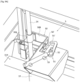
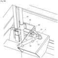
- the interface system 5 comprises two parts, a first part 50, called the fixed part, mounted on the actuating member 24 and a second part 51, called the movable part secured to the frame 10 of the interface device.
- the movable part 51 is intended to cooperate with the fixed part 50 to lock it in a so-called active safety position or to unlock it to correspond respectively to the blocking or unlocking of the actuating member 24 (the unlocking making it possible to act on the actuating member when it is desired to tilt the container).
- a non-limiting example of an interface system 5 is illustrated.
- the fixed part 50 of the interface system 5 is an adaptation kit part which must be fixed beforehand on the actuating member 24.
- the fixed part 50 comprises a portion 50A intended to be fixed on the actuating member 24, and a remote portion 50B provided with a light 50'.
- the portion 50A fixing on the actuating member 24 is for example a tubular sleeve threaded and mechanically fixed around the lever.
- the remote portion 50B has a shape adapted to the type of lever to be able to cooperate with the movable part 51.
- the remote portion 50B is in particular bent. As visible on the Figures 9A And 10 , the offset portion 50B here presents two examples of different shapes.
- This part of the adaptation kit is specifically designed for each container model in order to adapt perfectly to the actuating member which may be different depending on the manufacturer's model of the container.
- the movable part 51 is integral with the front end of the front part 11 of the interface device.
- the movable part 51 is integral with the transverse beam 11-1, preferably integral with one of the interface profiles 13 at its attachment portion on the transverse beam 11-1, which, because the interface profile 13 is movable, makes it possible to optimize the indexing of the interface system 5 with the actuating member (lever) 24.
- the movable part 51 is movable relative to the fixed part 50 (and therefore relative to the actuating member 24).
- the movable part 51 is preferably pivotable.
- the movable part 51 comprises a hook 51' which is intended to be introduced into the slot 50' of the fixed part 50 or to be uncoupled therefrom.
- the movable part 51 is able to adopt three positions, an open position for which the hook 51' is disengaged from the light 50' ( Figure 9A ), an intermediate position called active safety ( Figure 9B ) for which the hook 51' is (partially) engaged in the light 50' while being oriented angularly relative to the opening plane of the light 50' (i.e. at an angle not parallel to the opening plane of the light), and a so-called closed or unlocking position for which the hook 51' is fully engaged while being positioned beyond the light 50' and along a plane parallel to the opening plane of the light ( Figure 9C ).
- the movable part 51 comprises for example a rotating cam 52 and a jack 53, the translation of the jack 53 in one direction or the other generating the rotation of the cam 52 in one direction or the other and consequently the coupling or uncoupling of the hook 51' with the light 50'.
- the cam 52 is in the open position (the hook 51' is completely clear of the light 50') in order to be able to fix the fixed part 50 on the actuating member (lever) 24 and to install the container in the upright position on the interface device when it is taken with the forklift.
- the cam 52 is in the active safety position which places the hook 51' partially engaged in the light 50' and then prevents any tilting of the container 2 since the hook 51' is angularly blocked in the light and therefore prevents the container from pivoting/tilting forward.
- the cam 52 is in the unlocked position, which places the hook 51' parallel to the general plane of the light 50' allowing the container 2 to tilt.
- the light 50' which has a stop function, also has a suitable dimension (according to its longitudinal dimension parallel to the translation direction of the interface device) to allow tilting.
- the display means 9 transmit all the information to data processing means which are internal to the equipment block 12A and which can be transmitted remotely.
- the equipment block can also include RFID processing and communication means to communicate if necessary with the container 2 or the storage bin 4 or the forklift 3 which would be equipped with RFID chips.
- the visualization means 9 may comprise a scanner for reading the filling profile in the storage bin 4.
- FIG. 11 shows a variant of the interface device 1 which does not have a lifting system for the base 11A.
- the rolling or sliding members 15 are arranged at the front and rear distal ends of each of the side profiles 11-2 and 11-3.
- Each rolling or sliding member 15 has a bearing surface intended to bear against the upper end edge 40' of a standard storage bin 4.
- Each rolling member 15 here forms a rotating roller or roller with a rotary axis parallel to the general plane of the base 11A and perpendicular to the direction of the side profile.
- the figures 13 , 13A and 13B illustrate another embodiment of an interface device 1A which is not intended to be transported by forklift but which is permanently fixed against a dock where a storage bin 4 is located below.
- the interface device 1A also comprises a front part 11, a rear part 12, support means 13 for a handling container 2, a mobility structure 14 for translating the front part 11 relative to the rear part 12, rolling or sliding 15 mounted on the front part 11.
- the rear part 12 further comprises complementary means 13" for supporting the container 2 when the mobility structure 14 is folded in order to support the front part 11 and the container 2 in the void.
- the interface device 1A further comprises jacks 60 fixed to the rear part 12 and to the rear end of the mobility structure 14, the jacks 60 being able to pivot the front part 11 supported by the mobility structure 14 in order to lift it ( Figure 13A ) just appropriately for the passage and placement of the storage bin under the interface device 1A. Indeed, it is necessary to lift the front part 11 with the rolling or sliding members 15 to bring the storage bin 4 below (which is slid by pushing against the dock) then the jacks 60 are actuated again to lower the front part 11 so that the rolling or sliding members 15 rest on the edge 40' of the longitudinal sides of the storage bin.
- the handling container 2 positioned on the support means 13 of the front part 11 of said interface device, can be translated above the storage bin and away from the dock via the mobility structure 14 to fill the storage bin as it moves along its length.
- the translation is aided by the rolling members 15 positioned on the front part 11 of the interface device and along the lateral sides.
- the interface device 1A may comprise supports 80 arranged on the front part 11, the supports 80 serving to support the jacks 8 in the rest position (the jacks being cantilevered).
- THE figures 14, 14A And 14B show another embodiment of an interface device 1B of the invention.
- the interface device 1B does not need to be transportable by a forklift and therefore does not necessarily require forklift forklift passages.
- the interface device 1B is fixed to the ground while comprising the front part 11 in elevation, at the height of the upper plane of a storage bin 4.
- a handling container 2 located at ground level and on the interface device 1B can be brought up to the height of the bin 4 to then be moved above and along the bin.
- the interface device 1B is designed like the other interface devices 1 and 1A to be translated above and along a storage bin 4 thanks to the mobility structure 14 to move the front part 11 relative to the rear part 12 ( Figure 14B ).
- the front part 11 comprises a lifting system 16 which is of a different design from that of the lifting system of the interface device 1 of the Figure 1
- the lifting system 16 which is coupled to the support means 13 makes it possible to raise and lower the handling container 2, in particular to lower the container 2 in a plane which is lower than the upper and support plane of the rolling or sliding members 15 of the front part 11.
- the front part 11 In the folded position of the mobility structure 14, the front part 11 is located outside the storage bin 4, and the handling container 2 can adopt a low position at ground level and a high position at the level of the upper plane of the storage bin.
- the rear part 12 forms a seat structure of the interface device 1B and has a function in the manner of an elevator shaft for raising and lowering the handling container 2, while the front part 11 with its rolling or sliding means 15 always remains at the height of the upper translation plane, above the storage bin (in the folded or deployed position of the mobility structure 14).
- the rear part 12 comprises its base 12A resting on the ground and a stage 120 at which the front part 11 is arranged.
- the support means 13 of the handling container 2 form for example here a frame on which the container 2 rests and the lifting system 16 is connected to the frame 13.
- the interface system 5 for locking and unlocking the container 2 for its tilting is here constituted by the lifting system 16.
- the lifting system 16 carried by the front part 11 is for example a system with (vertical) chains and motorized sprockets, which is capable of supporting and carrying the container 2, locking it in position and unlocking it to tilt it.
- the container 2 is raised from the ground ( figure 14 ) via the 16 elevator system to floor 120 ( Figure 14A ), the mobility structure 14 then being in its folded position.
- the interface device 1B is positioned at the end of the storage bin 4, the rear part 12 being against the bucket with the stage 120 arranged outside the bucket and at the height of the upper plane of the bucket.
- the stage 120 comprises side members 121 which are in alignment with the longitudinal walls of the bucket 4 and whose upper edge 121' is coplanar with the upper end edge 40' of the longitudinal walls of the bucket.
- the rolling or sliding members 15 rest, in the folded state of the mobility structure 14 ( figure 14 ), on the side members 121 (on the edge 121' of the side members 121). When the mobility structure 14 is set in motion, the rolling or sliding members 15 cooperate (roll or slide) with the edge 121' of the side members 121 and then continue their path by cooperating with the edges 40' of the storage bin 4 ( Figure 14B ).
- FIG. 15 corresponds to the interface device 1B of the previous embodiment, with a less usual handling container 2.
- the container 2 is designed to include a rear tailgate 2' which can be folded down to be opened when unloading waste from a truck.
Landscapes
- Engineering & Computer Science (AREA)
- Mechanical Engineering (AREA)
- Transportation (AREA)
- Structural Engineering (AREA)
- Civil Engineering (AREA)
- Life Sciences & Earth Sciences (AREA)
- Geology (AREA)
- Forklifts And Lifting Vehicles (AREA)
- Handcart (AREA)
- Details Of Rigid Or Semi-Rigid Containers (AREA)
Applications Claiming Priority (1)
| Application Number | Priority Date | Filing Date | Title |
|---|---|---|---|
| FR2310784A FR3153816B1 (fr) | 2023-10-09 | 2023-10-09 | Dispositif d’interface de manutention d’un contenant notamment d’un contenant basculant |
Publications (1)
| Publication Number | Publication Date |
|---|---|
| EP4538218A1 true EP4538218A1 (de) | 2025-04-16 |
Family
ID=89474457
Family Applications (1)
| Application Number | Title | Priority Date | Filing Date |
|---|---|---|---|
| EP24205710.7A Withdrawn EP4538218A1 (de) | 2023-10-09 | 2024-10-09 | Vorrichtung zur handhabung einer schnittstelle eines behälters, insbesondere eines kippbehälters |
Country Status (2)
| Country | Link |
|---|---|
| EP (1) | EP4538218A1 (de) |
| FR (2) | FR3153816B1 (de) |
Cited By (1)
| Publication number | Priority date | Publication date | Assignee | Title |
|---|---|---|---|---|
| CN120841227A (zh) * | 2025-09-22 | 2025-10-28 | 赞皇县沃田农业开发有限公司 | 一种红枣加工分选自动上料装置 |
Citations (5)
| Publication number | Priority date | Publication date | Assignee | Title |
|---|---|---|---|---|
| FR2438009A2 (fr) * | 1978-10-03 | 1980-04-30 | Henon Bernard | Perfectionnements a un dispositif pour le transport et le basculement d'une charge au moyen d'un chariot elevateur a fourche |
| US4828450A (en) * | 1985-01-16 | 1989-05-09 | Brudi Equipment, Inc. | Universal fork-supported push-pull slip sheet handling attachment for forklift trucks |
| DE3943489C1 (en) * | 1989-04-15 | 1991-05-02 | Baumann Verwertungsgesellschaft Gmbh, 7958 Laupheim, De | Discharge mechanism for container transportable by forklift truck - uses container aperture boundary, forming engagement part, and spaced feet slotted parts |
| FR2958924A1 (fr) | 2010-04-19 | 2011-10-21 | Suc Ets | Dispositif pour chariot elevateur de basculement d'une benne basculante. |
| FR3114088B1 (fr) | 2020-09-14 | 2023-01-06 | Design Way | Ensemble de moyens pour la collecte de déchets issus du tri sélectif en porte à porte en zone urbanisée. |
-
2023
- 2023-10-09 FR FR2310784A patent/FR3153816B1/fr active Active
-
2024
- 2024-10-09 EP EP24205710.7A patent/EP4538218A1/de not_active Withdrawn
- 2024-10-09 FR FR2410936A patent/FR3153815B1/fr active Active
Patent Citations (5)
| Publication number | Priority date | Publication date | Assignee | Title |
|---|---|---|---|---|
| FR2438009A2 (fr) * | 1978-10-03 | 1980-04-30 | Henon Bernard | Perfectionnements a un dispositif pour le transport et le basculement d'une charge au moyen d'un chariot elevateur a fourche |
| US4828450A (en) * | 1985-01-16 | 1989-05-09 | Brudi Equipment, Inc. | Universal fork-supported push-pull slip sheet handling attachment for forklift trucks |
| DE3943489C1 (en) * | 1989-04-15 | 1991-05-02 | Baumann Verwertungsgesellschaft Gmbh, 7958 Laupheim, De | Discharge mechanism for container transportable by forklift truck - uses container aperture boundary, forming engagement part, and spaced feet slotted parts |
| FR2958924A1 (fr) | 2010-04-19 | 2011-10-21 | Suc Ets | Dispositif pour chariot elevateur de basculement d'une benne basculante. |
| FR3114088B1 (fr) | 2020-09-14 | 2023-01-06 | Design Way | Ensemble de moyens pour la collecte de déchets issus du tri sélectif en porte à porte en zone urbanisée. |
Cited By (1)
| Publication number | Priority date | Publication date | Assignee | Title |
|---|---|---|---|---|
| CN120841227A (zh) * | 2025-09-22 | 2025-10-28 | 赞皇县沃田农业开发有限公司 | 一种红枣加工分选自动上料装置 |
Also Published As
| Publication number | Publication date |
|---|---|
| FR3153815A1 (fr) | 2025-04-11 |
| FR3153816B1 (fr) | 2025-10-24 |
| FR3153816A1 (fr) | 2025-04-11 |
| FR3153815B1 (fr) | 2026-01-02 |
Similar Documents
| Publication | Publication Date | Title |
|---|---|---|
| FR2687654A1 (fr) | Structure pour permettre de charger ou decharger des marchandises a transporter avec un dispositif de manutention a bras de levage hydraulique. | |
| EP0194954A1 (de) | Vorrichtung zur Förderung und Verschiebung einer Last, z.B. eines Containers oder eines Kipperaufbaus auf einem Fahrzeug | |
| FR3153815A1 (fr) | Dispositif d’interface de manutention d’un contenant basculant, notamment pour coopérer avec une benne de stockage | |
| EP0374019A1 (de) | System zum Transportieren und Ablegen von mindestens einem Brückenteil von einem Fahrzeug, wie ein Pionierpanzer | |
| EP1214238B1 (de) | Zusammenklappbarer wagen | |
| WO2008110696A1 (fr) | Dispositif de protection pour un ascenseur et ascenseur comportant un tel dispositif | |
| EP1243463A1 (de) | Fahrzeug mit einer Vorrichtung zum Handhaben von einem Container und Verfahren für das Heben einer Last mit einem solchen Fahrzeug | |
| EP2253562B1 (de) | Transportvorrichtung für vorgefertigte plattenförmige Elemente | |
| EP3400622B1 (de) | Stationärer schutzraum zur aufbewahrung von mindestens einer stromspeichereinheit | |
| EP0889000A1 (de) | Gabelhubwagen | |
| EP0900692B1 (de) | Einheit aus abnehmbarer Karosseriebaugruppe und Trägerfahrzeug, Methode zum Kuppeln einer derartigen Einheit, sowie mit einer solchen Einheit ausgerüstetes Fahrzeug | |
| EP0377222B1 (de) | Ausziehleiter auf einem Fahrgestell | |
| EP0434880A1 (de) | Hebeeinrichtung für lasttragendes Kraftfahrzeug | |
| FR3076825A1 (fr) | Dispositif de chargement/dechargement d'un caisson sur/depuis un vehicule automobile et procede de commande associe | |
| EP1043267A1 (de) | Flurförderfahrzeug für ein Transportfahrzeug wie z.B. ein Sattelzug | |
| EP4520686A1 (de) | Kippanordnung zum entleeren eines behälters in einen sammelbehälter | |
| EP4299403B1 (de) | Wagenvorrichtung zum schienengebundenen transport von gütern auf paletten | |
| FR2563204A1 (fr) | Accessoire pour chariot a fourche, et procede de dechargement utilisant cet accessoire | |
| EP2162371A2 (de) | Vorrichtung zum empfangen einer struktur zur aufnahme durch ein trägerfahrzeug mit einem greifarm oder einer rampe | |
| FR2941185A1 (fr) | Vehicule equipe d'un systeme de manutention pour contenants amovibles | |
| FR2940937A1 (fr) | Dispositif de support destine a faciliter le chargement d'un caisson ou d'un plateau sur une plate-forme | |
| FR2946943A1 (fr) | Chariot pour le transport de pieces de carrosserie de vehicule | |
| EP4624700A1 (de) | Mobile wartungsanlage für fahrzeuge | |
| FR3152796A1 (fr) | Systeme de levage et nettoyage pour benne, pour successivement vider et nettoyer un conteneur | |
| FR2899214A1 (fr) | Installation pour lever et renverser un conteneur |
Legal Events
| Date | Code | Title | Description |
|---|---|---|---|
| PUAI | Public reference made under article 153(3) epc to a published international application that has entered the european phase |
Free format text: ORIGINAL CODE: 0009012 |
|
| STAA | Information on the status of an ep patent application or granted ep patent |
Free format text: STATUS: THE APPLICATION HAS BEEN PUBLISHED |
|
| AK | Designated contracting states |
Kind code of ref document: A1 Designated state(s): AL AT BE BG CH CY CZ DE DK EE ES FI FR GB GR HR HU IE IS IT LI LT LU LV MC ME MK MT NL NO PL PT RO RS SE SI SK SM TR |
|
| STAA | Information on the status of an ep patent application or granted ep patent |
Free format text: STATUS: THE APPLICATION IS DEEMED TO BE WITHDRAWN |
|
| 18D | Application deemed to be withdrawn |
Effective date: 20251017 |