EP4520686A1 - Kippanordnung zum entleeren eines behälters in einen sammelbehälter - Google Patents
Kippanordnung zum entleeren eines behälters in einen sammelbehälter Download PDFInfo
- Publication number
- EP4520686A1 EP4520686A1 EP24199396.3A EP24199396A EP4520686A1 EP 4520686 A1 EP4520686 A1 EP 4520686A1 EP 24199396 A EP24199396 A EP 24199396A EP 4520686 A1 EP4520686 A1 EP 4520686A1
- Authority
- EP
- European Patent Office
- Prior art keywords
- supporting structure
- container
- bucket
- tipper
- recess
- Prior art date
- Legal status (The legal status is an assumption and is not a legal conclusion. Google has not performed a legal analysis and makes no representation as to the accuracy of the status listed.)
- Pending
Links
Images


Classifications
-
- B—PERFORMING OPERATIONS; TRANSPORTING
- B65—CONVEYING; PACKING; STORING; HANDLING THIN OR FILAMENTARY MATERIAL
- B65F—GATHERING OR REMOVAL OF DOMESTIC OR LIKE REFUSE
- B65F1/00—Refuse receptacles; Accessories therefor
- B65F1/12—Refuse receptacles; Accessories therefor with devices facilitating emptying
- B65F1/122—Features allowing the receptacle to be lifted and subsequently tipped by associated means on a vehicle
-
- B—PERFORMING OPERATIONS; TRANSPORTING
- B65—CONVEYING; PACKING; STORING; HANDLING THIN OR FILAMENTARY MATERIAL
- B65F—GATHERING OR REMOVAL OF DOMESTIC OR LIKE REFUSE
- B65F1/00—Refuse receptacles; Accessories therefor
- B65F1/02—Refuse receptacles; Accessories therefor without removable inserts
-
- B—PERFORMING OPERATIONS; TRANSPORTING
- B65—CONVEYING; PACKING; STORING; HANDLING THIN OR FILAMENTARY MATERIAL
- B65F—GATHERING OR REMOVAL OF DOMESTIC OR LIKE REFUSE
- B65F1/00—Refuse receptacles; Accessories therefor
- B65F1/14—Other constructional features; Accessories
- B65F1/1452—Lifting, hoisting, elevating mechanisms or the like for refuse receptacles
-
- B—PERFORMING OPERATIONS; TRANSPORTING
- B65—CONVEYING; PACKING; STORING; HANDLING THIN OR FILAMENTARY MATERIAL
- B65F—GATHERING OR REMOVAL OF DOMESTIC OR LIKE REFUSE
- B65F3/00—Vehicles particularly adapted for collecting refuse
- B65F3/02—Vehicles particularly adapted for collecting refuse with means for discharging refuse receptacles thereinto
-
- B—PERFORMING OPERATIONS; TRANSPORTING
- B65—CONVEYING; PACKING; STORING; HANDLING THIN OR FILAMENTARY MATERIAL
- B65F—GATHERING OR REMOVAL OF DOMESTIC OR LIKE REFUSE
- B65F3/00—Vehicles particularly adapted for collecting refuse
- B65F3/02—Vehicles particularly adapted for collecting refuse with means for discharging refuse receptacles thereinto
- B65F3/04—Linkages, pivoted arms, or pivoted carriers for raising and subsequently tipping receptacles
- B65F3/06—Arrangement and disposition of fluid actuators
-
- B—PERFORMING OPERATIONS; TRANSPORTING
- B65—CONVEYING; PACKING; STORING; HANDLING THIN OR FILAMENTARY MATERIAL
- B65F—GATHERING OR REMOVAL OF DOMESTIC OR LIKE REFUSE
- B65F3/00—Vehicles particularly adapted for collecting refuse
- B65F3/02—Vehicles particularly adapted for collecting refuse with means for discharging refuse receptacles thereinto
- B65F3/08—Platform elevators or hoists with guides or runways for raising or tipping receptacles
-
- B—PERFORMING OPERATIONS; TRANSPORTING
- B65—CONVEYING; PACKING; STORING; HANDLING THIN OR FILAMENTARY MATERIAL
- B65F—GATHERING OR REMOVAL OF DOMESTIC OR LIKE REFUSE
- B65F3/00—Vehicles particularly adapted for collecting refuse
- B65F3/14—Vehicles particularly adapted for collecting refuse with devices for charging, distributing or compressing refuse in the interior of the tank of a refuse vehicle
- B65F3/20—Vehicles particularly adapted for collecting refuse with devices for charging, distributing or compressing refuse in the interior of the tank of a refuse vehicle with charging pistons, plates, or the like
- B65F3/201—Vehicles particularly adapted for collecting refuse with devices for charging, distributing or compressing refuse in the interior of the tank of a refuse vehicle with charging pistons, plates, or the like the charging pistons, plates or the like moving rectilinearly
-
- B—PERFORMING OPERATIONS; TRANSPORTING
- B65—CONVEYING; PACKING; STORING; HANDLING THIN OR FILAMENTARY MATERIAL
- B65F—GATHERING OR REMOVAL OF DOMESTIC OR LIKE REFUSE
- B65F7/00—Cleaning or disinfecting devices combined with refuse receptacles or refuse vehicles
- B65F7/005—Devices, mounted on refuse collecting vehicles, for cleaning or disinfecting refuse receptacles
-
- B—PERFORMING OPERATIONS; TRANSPORTING
- B65—CONVEYING; PACKING; STORING; HANDLING THIN OR FILAMENTARY MATERIAL
- B65F—GATHERING OR REMOVAL OF DOMESTIC OR LIKE REFUSE
- B65F3/00—Vehicles particularly adapted for collecting refuse
- B65F2003/006—Constructional features relating to the tank of the refuse vehicle
-
- B—PERFORMING OPERATIONS; TRANSPORTING
- B65—CONVEYING; PACKING; STORING; HANDLING THIN OR FILAMENTARY MATERIAL
- B65F—GATHERING OR REMOVAL OF DOMESTIC OR LIKE REFUSE
- B65F3/00—Vehicles particularly adapted for collecting refuse
- B65F3/02—Vehicles particularly adapted for collecting refuse with means for discharging refuse receptacles thereinto
- B65F2003/0263—Constructional features relating to discharging means
- B65F2003/0276—Constructional features relating to discharging means capable of moving towards or away from the vehicle
Definitions
- the present invention relates to a container tipper for a collection vehicle, and in particular for waste collection, designed to ensure the unloading of the contents of a container into a skip, for example capable of being received at the rear of a vehicle.
- a collection vehicle equipped with such a tipper arrangement is also proposed.
- a collection vehicle used in particular for collecting waste, comprises a skip positioned at the rear of said vehicle, and is advantageously equipped with a tipper, configured to grip a container, at a lip surrounding the discharge opening of the container, and to tip said container relative to the skip, so as to cause the contents of the container to be discharged, under the effect of gravity, into said skip through an opening provided in this skip.
- a container tipper arrangement transportable by a collection vehicle, comprising a skip with an upper opening (opening which can extend in a substantially horizontal plane), with improved reliability and reduced cost, operation and maintenance costs.
- each container can be brought against a side wall of the skip equipped with the tipper, with ergonomics compatible with transport of the skip without the arrangement significantly exceeding the size of this skip.
- the external cavity and the parts of the wall which delimit it can entirely form part of the size of the skip.
- a space dedicated to the tipper (external space) and a space dedicated to dumping (internal space) can thus be formed, these two spaces being separated from each other by a longitudinal portion of the wall of the first side wall.
- the tipper can be controlled independently, even if the skip is placed on the ground. This allows the truck to be freed up, so that it can only be used for transporting a skip loaded beyond a threshold or loaded for a cycle or storage period considered sufficient.
- the possibility of not modifying the truck is an advantage for use (possibility of filling the dumpster placed on the ground/using the truck or vehicle for another purpose).
- the supporting structure may be supported by a slider or movable pivot part, which defines a pivot axis of the supporting structure.
- the slider is movably mounted on the guide part, for example in rails of this part.
- the slider may also carry one or more actuators (by an articulated attachment, typically), such as cylinders, the movable head of which is coupled/fixed in an articulated manner to fixing means formed in the supporting structure, for example on an inner side of this supporting structure knowing that the gripping member is located on an external side of the supporting structure.
- the slider and the cylinders/actuators can be entirely housed in the recess, in particular by being covered by the supporting structure which can form an element closing (at least in part) access to the recess, in the retracted configuration.
- the slide and the actuators carried by the slide can be controlled by a control unit which activates for example a lift to first raise the slide, before actuating a relative pivoting of the supporting structure with respect to the slide.
- This sequence of movements can be programmed to avoid pivoting the supporting structure when the pivot axis has not been sufficiently moved/lifted to reach or exceed the upper side of the bucket.
- the arrangement comprises means for disengaging and/or moving the supporting structure, in order to place the gripping member outside the recess with this member moving away from the first wall.
- This can allow the gripping member to be shifted, for example to position this member at the level of a sidewalk edge.
- this shift is done with an inclination allowing, in the event of lowering of the gripping member with a lower portion of the supporting structure, to follow an external lowering trajectory relative to a part of the underlying frame, present in line with the external cavity forming the recess.
- the movement of the gripping member, with partial disengagement of the supporting structure may be a lowering by displacement of at least one portion (lower/lower portion) of the supporting structure, possibly at an angle.
- the means for disengaging the supporting structure may generate two movement trajectories, in order to move and shift this member into a lowered position.
- Such means are arranged by default behind the external face defined by the first side wall.
- the shifted position for the gripping member may therefore be obtained by displacement and/or deployment of the supporting structure from the retracted position, preferably by limiting the amplitude of the movement away from the external face: for example, the supporting structure may remain attached or almost attached to the chassis, for example by covering anti-underride barriers of the truck carrying the dumpster.
- the means for disengaging and/or moving the supporting structure may optionally comprise at least one tilting cylinder or actuator configured and controlled to initiate this tilting after a first substantially vertical (or slightly inclined) lifting phase, for example following a generally rectilinear direction defined by the guide part.
- the gripping member may in this case move further and further away from the recess with a trajectory bypassing the recess from above. When this member is located at least halfway up, it may already be offset (towards the outside of the first side wall) or still located in an upper half of the recess.
- the gripping member can pivot with the container: the tilting action results, for example, from the actuation of one or more tilting cylinders initially arranged vertically in the recess.
- the gripping member may be provided with a comb forming a lower part of a jaw of the supporting structure.
- the comb may have teeth oriented upwards in the retracted configuration. After tilting, they are inclined and oriented downwards, towards the interior volume.
- the moving means may further have actuator members, such as tilting cylinders, in order to actuate a pivoting of the supporting structure beyond the upper lateral edge.
- actuator members such as tilting cylinders
- one or more of the actuators include hydraulic or pneumatic cylinders, optionally cylinders allowing braking to be carried out at the end of the stroke of the cylinder in question.
- a vertical arrangement for each of these cylinders may be adopted, in the retracted configuration.
- the tipper can be integrated in a compact manner, without extending beyond the body's clearance or extending downwards beyond a floor or lower surface of the body. This is a safety advantage: it is thus possible to keep the underride guards between the truck's wheels.
- the bucket has an electrical power source and a control station, connected to the power source, for controlling the tipper autonomously, for operation of the tipper compatible with a mode of use of the bucket directly on the ground.
- the arrangement may be compatible with cleaning carried out from above the skip. All or part of the supporting structure may be used to guide the dumping, allowing it to be obtained, alone or in association with a partition or dumping ramp provided on the skip, a barrier effect above the recess in the tilted state.
- the arrangement without requiring further intervention from an operator, promotes complete dumping of the contents of the container into the skip and a return of the emptied container in a cleaned state.
- the Z direction designates the vertical direction of space while the bucket 2 is extended in a horizontal direction.
- the tipper 1 is configured to carry out the dumping of the contents of a container 10, in a state mounted on a collection tank part for receiving these contents.
- a bucket 2 is provided to form such a collection tank part.
- the bucket 2 has two side walls 200, 200', parallel to each other, which can delimit between them a significant interior volume V, for example exceeding one or several tens of cubic meters.
- the door of the rear part 22 can be hinged if necessary if necessary, for example around a horizontal axis when the door is made in a single pivoting block.
- the front wall end 21 may include a maneuvering socket 2b accessible from the outside.
- Each side wall 200, 200' extends upwards from a bottom 2a.
- the bucket 2 may optionally have an upper reinforcing belt.
- the interior volume V is locally reduced on the side of the side wall 200, for example in an area distant from the rear part 22.
- a movable floor and/or transfer means on board at a base 2a of the skip 2 can also participate in evacuating a collected part towards the rear, by making more available the space (of the volume V) located at the front and at the level of which a container 10 maneuvered using the tipper 1 is unloaded.
- the bottom or base 2a can constitute or include a load-bearing floor.
- the skip 2, when it is of the “ampirole” type, can include one or more rollers r2 arranged on a rear side, two lower reinforcement and guide slides G1, G2.
- the tilter 1 is provided with a member 1c or part for gripping the container 10 making it possible to block the container 10, for example by clamping or pinching against a comb 14 capable of coming from below a rim or lip 9 provided on the container 10.
- a rim/lip 9 is generally provided on the periphery of the upper end E10 of a container 10, where the opening O is located for filling and pouring (into the bin).
- the comb 14 or similar relief assembly can be moved, for example lowered then slid to rise relative to the counter-comb 14', so as to hold and lift a container 10 by means of its rim 9.
- the supporting structure 5 is movable around a pivot axis A which is movable in height, along the guide part 4.
- the tilting arrangement 100 may have actuators or means for disengagement and lowering operating independently of the actuators or lifting means ML.
- lowering means MA are provided making it possible to lower the gripping member 1c, from a first position corresponding to the height level occupied in the retracted position of the supporting structure 5, in order to reach a lowered position in a first operating mode of the tilting device 1 compatible with a configuration of the bucket 2 mounted on a chassis of a truck 60 or collection vehicle.
- the supporting structure 5 in the retracted position may typically be located higher than this lowered position.
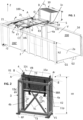
- the tipper 1 can be carried by the bucket 2 by being fixed in the recess 2c, so as to occupy a substantially parallelepipedal volume, for example with a height H1 of the tipper 1 which can be substantially equal to the height h2 of the receiving/tank part of the bucket 2. More broadly, the tipper 1 can be designed and dimensioned to be taller than it is wide, and with a depth limited to less than 55 cm, for example of the order of 40 cm, in a retracted state as seen in particular on the Figure 4 .
- Height H1 may slightly exceed height h2, for example at the end upper E4 of the guide part 4.
- the guide part 4 has tenons, similar axis elements or bearings 8 which make it possible to make this guide part 4 articulated around an axis X1 while being connected to the support 3.
- a tilting actuation of this guide part 4 can be carried out in an area adjacent to or located at the bottom of the recess 2c, by using jacks V1 or similar actuators capable of pushing outwards the lower end E4' of the guide part 4.
- the fixing support 3 can be designed to support the guide part 4 of the rocker 1 both by an upper end, capable of carrying parts of axes 4r or similar parts of a hinge or articulation (forming the axis X1), and by a lower end with the actuator(s)/jack(s) V1.
- the actuators in particular the VL cylinders of the tipper 1 capable of driving the lifting of the supporting structure 5 can be entirely maintained in the recess 2c, for example by each having a fixing connection 4c provided on a fixing support 3 allowing the guide part 4 to be secured to the bucket 2.
- This fixing connection 4c is compatible with a rotation about an axis (which can be a horizontal axis) of each VL cylinder.
- a crossed arrangement of two VL cylinders can optionally be provided, as illustrated in the figures 2 And 4 , in order to compactly house these actuators for lifting the supporting structure 5.
- the cylinder heads ev of these VL cylinders, attached to the slide 15 via fittings 15c which may be opposite each other, are kept aligned along a horizontal axis.
- this may be edged/arranged between two parallel sides of a similarly rigid, fixing frame or support 3, which remains fixed relative to the bucket 2.
- a similarly rigid, fixing frame or support 3 which remains fixed relative to the bucket 2.
- At least two crosspieces T3, one lower and the other upper, can connect these sides.
- a fixing support 3 designed independently and fixedly mounted on the bucket 2 is shown, in order to support a guide part 4 which is typically distributed on two sides by forming rails 4a, 4b for the sliding of the movable part of the tipper 1.
- the support can be an integral part of a wall 200 (first side wall) of the bucket 2, this support 3 being present/provided in the design of the bucket 2 in the latter case.
- a certain number of jack(s) or similar actuators may be provided.
- the actuators may be hidden (not visible in side view of the bucket) when the tipper 1 is in its rest configuration.
- a control unit or panel 16 may also be secured to the bucket 2, for example on a front side of the recess 2c, near the front wall end 21 of the bucket.
- a control interface, in connection with a cylinder control module, may be provided mobile within this control unit, for example to allow an operator to move away from the container 10 to be unloaded while having remote control functions.
- An intermediate sliding part or slider 15 and a tilting portion 12 can be coupled to each other, being able to adopt a parallel starting conformation (with overlap) in which the slider 15 is covered, in the recess 2, by a plate constituting the tilting portion 12.
- the tilting portion is an upper portion 12 which has connections with a lower portion 11 which partially covers it from the outside in order to make available a comb 14 facilitating the gripping of a container 10.
- the slider 15 can extend into the recess 2c while being covered by the part or parts, preferably flat (arranged vertically), forming the tilting part of the supporting structure 5.
- the supporting structure 5, which may be substantially flat, extends for example along a substantially vertical plane in the retracted position which is a starting position.
- the gripping member 1c provided in the supporting structure 5 can operate without losing the flat conformation of the supporting structure.
- the gripping member 1c consists of reliefs formed on an outer face of a lower portion 11 of the structure 5. This is for example a comb 14 forming a lower part of a jaw of the rocker 1.
- the lower portion 11 may then be a part slidably mounted along an outer face of another portion 12 of the structure 5 which is capable of rocking for a raised level of the supporting structure 5.
- the portion 12 serves as a guide to portion 11 and extends higher, including a counter-comb 14' or relief adapted to form a stop for the container 10 when the comb 14 is raised (due to an integral movement of the lower portion 11) as close as possible to the counter-comb 14'.
- the raising of the comb 14 is schematically reflected by the arrow T1 on the figure 8 and may, if container 10 is seized, be immediately followed by an additional lift corresponding to the lifting of container 10 and the raising of axis A (lift reflected by arrow TL).
- the jaw function of the supporting structure 5, which may be optional, makes it possible to easily block the container 10, by taking advantage of a selective mobility of the lower portion 11, permitted for example by cylinders or similar actuators forming lowering means MA.
- a lowering of the gripping member 1c may be provided, if necessary after an offset or disengagement of the latter to allow easier engagement of the container 10, in particular if the bucket 2 is raised, for example by being mounted on a truck chassis 61 (see the Figures 6 and 7A For example).
- the lifting applies to an assembly comprising a slide 15 and the supporting structure 5.
- the slide 15 includes connections 15c to follow the extension of the VL cylinders or similar active actuators to obtain the movement of this assembly along the TL trajectory.
- direction D illustrates a non-limiting example of final inclination that can be obtained for the container 10 and the supporting structure 5 (here substantially flat) with which it is engaged.
- the opening O of the container 10 is thus oriented downwards at the end of the tilting, towards the interior volume V.
- a ramp 24 covering the recess 2c from above, as visible in the example of the Figure 10 , the contents can be poured into the bucket 2.
- the ramp 24 can constitute a fluid-tight wall element, allowing liquid exiting through the opening O to flow into the interior volume V.
- the ramp 24 is optionally wider than the free end 5a of the upper portion 12.
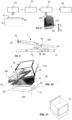
- the upper portion 12 may have an extension 12c, located beyond a zone of attachment to a shaft or axis element(s) making it possible to define the pivot axis A, so that this extension 12c is located higher and in line with the recess in the tilted position of the supporting structure 5, as can be seen in particular in the Figure 10 .
- the extension 12c may be located above (entirely above) the gripping member 1c in the retracted position. In the tilted position, an overlap may be provided between a plate forming this extension 12c (and thus forming the free end 5a of the supporting structure 5), on the one hand, and the ramp 24 on the other hand.
- This ramp 24 can be either stationary and inclined (downwards), up to a dumping edge 24b, with an angle of inclination A5 similar to that of the structure 5 in the tilted state, or movable to reach this inclined position in response to an actuation of a drive member, for example by carrying out a downward thrust on a part of the ramp 24.
- the angle of inclination A5 substantially identical to that of the supporting structure 5 with respect to the horizontal, can be greater than 20°, for example between 30° and 75°.
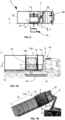
- This type of movement of the supporting structure 5 can be implemented both in the case of the Figure 7A , with the dump body on the chassis 61 of a truck 60, than in the case of the Figure 7B when skip 2 has been placed at a collection point allowing the truck 60 to carry out other transport operations.
- the guide part 4 can also pivot, for example by being pivoted slightly in the recess 2c to bring out, out of the recess 2c, the lower end E4' of the guide part 4, for example as explained above using jacks V1 which, in an undeployed state, can have a length typically less than or equal to the depth of the recess 2c.
- the support 3 can be dimensioned with a depth L1 equal to or slightly less than the depth of the recess 2c.
- the direction D' reflects for example an inclination of the guide part 4 which supports the supporting structure 5, by rotation around an angle which is possibly less than or equal to 15 or 20°.
- the arrangement 100 may have means for (partially) disengaging and/or moving the supporting structure 5, in order to make the gripping member 1c accessible, outside the recess 2c and for example allowing a lowering of this gripping member if necessary, taking into account the possible offset (in height) of the recess 2c relative to the ground. This can be achieved with a linear lowering trajectory (following the direction D', for example) passing close to the chassis but without interfering with the latter.
- the offset of the guide portion 4 may be limited and the rocker 1 may be devoid of articulated arm(s) which may generate awkward bulk and/or control difficulties.
- the lower end E4' of the guide portion 4 may be offset by less than 40 cm, for example less than 30 cm.
- Such a movement of the guide part 4 around the axis X1 amounts to pre-positioning the supporting structure 5 in the direction D' ( Figure 2 ) which is the guiding direction (cf. inclination of the guiding part 4, which may be globally less deep than the recess 2c in the initial/non-deployed configuration of the rocker 1) both during lowering and during lifting.
- This type of pre-positioning may correspond to an operating mode reflecting the case of the Figure 7A or similar.
- the inclination of the guide part 4, which supports the supporting structure 5, is obtained by rotation around the axis X1 with an angle which is possibly less than or equal to 15 or 20°, compatible with the reduced depth dimensions of the guide part 4.
- the VL lifting cylinders or actuators can also be located set back (further towards the bottom) from the guide part 4, optionally by being supported by a lower portion of the guide part 4 which projects towards the bottom from rails 4a, 4b or similar guide uprights.
- the movement of the guide part 4 can be actuated opposite the end E4 where the axis X1 is located, as seen in particular on the Figure 4 , and can make it possible to limit the offset or disengagement to a lower part of the supporting structure 5 and/or to then avoid resorting to a rotation to lift the container 10 along the side wall 200.
- the supporting structure 5 can be lifted by a simple linear displacement, at least initially to move the opening O of the container 10 substantially to the same level as the upper edge 2d.
- the supporting structure 5 consists mainly of two plates or portions 11, 12 with the lower portion 11 assembled as a partial covering plate of the upper portion 12, by covering a lower region of the upper portion 12.
- the slider 15 may be provided with two lateral flanges arranged internally, along the rails 4a, 4b of the guide part 4.
- a cylindrical section, forming the pivot for rotation of axis A, is provided in the slider 15 by extending from one to the other of the two flanges, for example by being joined to respective upper ends of these flanges.
- the cylindrical section or shaft 15a participates in maintaining an arrangement of the supporting structure 5 which is, in the retracted configuration, parallel to the rails 4a, 4b.
- the lower portion 11 may be mounted to slide relative to the upper portion 12 of the structure 5, with, where appropriate, guidance of the lower portion 11 between two wings 18 with return or lateral guides provided on the upper portion 12.
- a plate design may be adopted at least for one of the two portions 11, 12, so as to limit the depth requirement (in the recess) of the supporting structure 5.
- the lower portion 11 may overlap the upper portion 12, parallel to the latter, from the outside when the lateral guides/wings 18 are formed to project outwards relative to the rest of the plate constituting the upper portion 12.
- the lowering of a comb 14 or similar gripping area of the structure 5 may, in options preferred, to be activated once the inclination of the guide part 4 has been obtained, which allows, if necessary, to bypass embedding barriers 62, visible on the Figure 7A , and/or another part of the chassis 61.
- the upper portion 12 includes a spill sub-portion formed by the extension 12c which extends above the counter-comb 14' in the retracted position of the supporting structure 5. During tilting, the contents of the container 10 can slide on the extension 12c forming this spill sub-portion.
- the lower portion 11, arranged as a comb holder, may include an insertion end E11 (formed higher than the comb 14) capable of being inserted under the extension 12c, knowing that the upper portion 12 may delimit, typically under the extension 12c, a sliding passage for the lower portion, this passage being able to be delimited between the two guide wings 18 distributed on two sides of the upper portion 12.
- Such a passage, of width Lb may be substantially as wide as the width Le of the lower portion 11 as measured at the insertion end E11.
- the format or perimeter of the lower portion 11 may be generally rectangular.
- the lower portion 11 and the upper portion 12 can form a tiltable device whose maximum width is - preferably - less than the spacing between the rails 4a, 4b of the guide part to allow total or partial embedding of the supporting structure 5.
- the supporting structure 5 may be coupled to a slider 15, the coupling of which to the guide portion 4 prevents it from rotating around the axis A which may be formed by the shaft 15a of this slider 15.
- the slider 15 is arranged further inside/at the bottom of the recess 2c.
- the supporting structure 5 is dimensioned so as not to protrude outwards or to protrude less than 10 cm outwards, compared to an external face of the guide portion 4.
- This structure 5 may have a small depth/thickness, for example to represent an excess thickness e (without taking into account the comb 14 and the counter-comb 14') of less than 10 or 15 cm compared to the slider 15, in the retracted position.
- the supporting structure 5 may consist of only two parts, with only the upper portion 12 connected to the tilting actuators or cylinders VB, for example by fixing each head of the cylinder VB to a connecting element 12b rigidly formed on a rear face of the upper portion 12.
- a connecting element 12b may be offset lower than the pivot axis A and the position of the receivers or bearings 12 for the articulated coupling of the supporting structure 5.
- the jack(s) VB form actuating members for a pivoting of the supporting structure 5 beyond said lateral upper edge 2d, being activated only for a raised position as shown in the Figure 2
- the cylinder(s) VB are here supported by the slider 15, via the first hinge fixing regions 15f, following the upward trajectory TL before deploying by pushing the supporting structure from the recess 2c, typically without the slider 15 leaving the recess 2c.
- the recess 2c only moderately reduces the width of the bucket 2, for example without the depth L1 or that of the recess 2c exceeding 25 or 30% of the nominal width of the interior volume V.
- the recess 2 has for example a depth limited to less than 50 or 55 cm, having a bottom face F2 which can be substantially vertical and/or parallel to the rest of the internal face of the first wall 200 (following the direction Z in the case of the figures).
- the extension of the recess 2c can be limited to less than 2 meters, possibly less than 1.6 meters.
- the recess 2c can, along the wall 200, be delimited between two edges with a spacing d1 which represents less than 30% or 35% of the total length of the bucket 2, without overlapping/without interfering with the rear half Va of the interior volume V.
- the tipper 1 may be associated with a cleaning device or tool 7 which is mounted on the bucket 2, so as to be able to direct one or more liquid spray jets inside the container 10 via the opening O when the latter is in the tilted position, above of the upper side edge 2d.
- side walls 200, 200' and possibly the front wall end 12 may have spray bars 17 or similar liquid spraying members for cleaning and/or rinsing the bucket on the internal side.
- the cleaning tool 7 can be integrated on a front side of the bucket, for example without extending to the side of the rear half Va of the interior volume V.
- the bucket 2 may carry a liquid tank T in connection with the cleaning tool 7 and, if applicable, with the spraying booms 17.
- the tank T may be located in the interior volume V, offset forwards relative to the dumping region/zone ZD. While the tank T extends essentially or entirely under the upper edge of the bucket 2, the cleaning tool 7 may be carried by the bucket 2 and installed movably so as to be able to move on top of the bucket 2, typically above the interior volume V so as not to interfere with the unloading enabled by the tipper 1.
- a chassis having two sides C1, C2 is arranged on the bucket 2 transversely, being fixed both on the top of the first wall 200 and on the top of the second wall 200'.
- the fixing on the first wall 200 can be carried out on either side of the upper end of the guide part 4.
- the spacing between the two sides C1, C2 can correspond to a wide zone including the zone ZD for unloading the contents of the container 10.
- a frame of the cleaning tool 7 can be arranged only on one side relative to the spill region/zone ZD of the contents of the container 10 and/or only opposite the recess 2c, without connection to the first wall 200.
- the frame C1, C2 or similar attachment support may extend cantilevered above the bucket 2, in particular from an upper edge 2g of the bucket which is opposite the edge delimited above the recess 2c, so that the cleaning tool 7 occupies by default a retracted position, being arranged at a distance from the upper edge 2d.
- This tool 7 may have one or more movable cleaning head(s) 7a.
- the movable head 7a is movable relative to the attachment support or frame, being able to be brought closer/moved towards the upper edge 2d of the first wall 200.
- the cleaning head 7a is fluidically connected, for example via a suitable pipe or hose, to a liquid reservoir and adapted to spray the liquid above the upper edge 2 in a direction D7 away from the upper edge 2g (second edge) provided on the wall 200'.
- a pump for pressurizing the liquid may be provided in the circuit supplying the liquid to the cleaning head 7a.
- the tool 7 may be oriented differently, possibly having the head 7 closer to the second edge 2g than to the first upper edge 2d where the pouring takes place.
- the retraction configuration is thus distal to the first upper edge 2d, with for example a spacing of the tool 7 of at least half a bucket width relative to the pivot axis A.
- An activation via the control unit 16, can coordinate the movement of a VN cylinder or cylinder assembly to obtain an inclined position of the cleaning head 7a, which can extend to the extension position (maximum or with still a possibility of extension via the movement F7 if the cleaning head 7a has a telescopic design).
- a controller of the unit 16 can adjust/activate the pump to start the spraying operation.
- FIG 10 shows an example of positioning of the cleaning tool 7 enabled by a rotational movement which tends to lift the cleaning head 7a. This lifting may involve a rotation with straightening of the tool 7 then possibly a lowering of the latter until the axis X7 of elongation of the tool 7 is oriented towards an interior of the container 10 held in cantilever by the tilter 1).
- the supporting frame 6 or equivalent mobile support, on which the cleaning head 7a is fixed is mounted articulated on the fixed chassis C1, C2.
- This arrangement can make it possible to store the cleaning tool 7 flat, with the chassis C1, C2 substantially horizontal, with simple single rotation kinematics which can limit the rotation angle (to less than 180°, for example to less than 150°) of the supporting frame 6 to make it possible to reach the cleaning configuration.
- the movement of the supporting frame 6, from above, is compatible with a skip 2 whose loading height is significant, for example significantly exceeding the mid-height of the skip.
- a sliding movement can be actuated, along a substantially horizontal guide, here a rail element R for example, which is mounted on the top of the bucket 2, by using a mounting support SM (carrying the tool 7) capable of sliding in a transverse direction perpendicular to the length extension of the bucket 2.
- the SM mounting bracket is configured to slide and, simultaneously, straighten into a more raised position, to extend in an inclined orientation of direction similar to that (direction D7) shown in the Figure 10 .
- a sliding connection 7c of the SM support possibly using a roller, a rack or the like, may be combined with pivot connection parts 70, 72, attached to the SM support on which the tool 7 is mounted.
- connection arm(s) 72 which is/are hingedly connected to the guide without the possibility of sliding
- the entire SM support is pulled towards the edge 2d while further tilting the tool 7 due to the rotation of the SM support around a movable axis A7 (movable along the rail element R in the case of the figure 9 ) coinciding with the roller or similar sliding member.
- the cleaning tool 7 can be approached from the edge 2d by a support or carrying frame 6 or SM, where appropriate with the possibility of actuating a telescopic movement (see arrow F7 on the Figure 1 ) of the cleaning head 7a when the latter is already in its operational orientation for spraying liquid.
- a telescopic movement see arrow F7 on the Figure 1
- the cleaning tool may have a selectively movable design of the cleaning head, preferably so as to allow it to extend above/in line with the recess or similar integration zone of the tilter (or even beyond such an area), typically to insert itself inside a container 10 which is tilted.
- the cleaning head 7a is pivotable, for example by being made rotatable relative to its mounting bracket SM, 6, so that it can be angularly moved away from the operational direction for spraying liquid. Being able to move the cleaning tool 7 away/move more than 90° between the retracting configuration and the cleaning configuration can facilitate assembly of the tool.
- the tipper arrangement 100 can allow the supporting structure 5 to be lowered to leave the retracted position, preferably without deploying the gripping member 1 too far from the plane P of the wall 200 where the tipper 1 is located.
- the container 10 is previously opened, by moving the lid into a folded position against a side of the container 10 which is typically the one opposite the side engaged by the gripping member 1c.
- the supporting structure 5 before engaging an open container 10 on the tipping arrangement 100, the supporting structure 5 can be previously moved, from the embedded position, without extracting any tipping axis A of the structure 5 outside the gauge of the bucket 2, such an axis A then being able to be kept in the recess 2c. It is in response to the actuation of lowering means MA that the lower portion 11 of the supporting structure 5 can be lowered to allow the engagement of a comb 14 or similar gripping zone on a container 10, on one side of the bucket 2, for example without lateral spacing d (cf. Figure 6 ) greater than 40 or 50 mm between the container 10 and the plane P of the corresponding side face FL of the bucket 2, when the lower portion 11 is lowered, which corresponds to a step 52 on the figure 8 .
- d lateral spacing
- the container 10 lifted by the structure 5 remains held close to the face FL.
- the assembly of the structure 5 can be adapted so that the container 10 gradually approaches the face FL at the start of lifting, optionally without the container 10 entering the recess 2c (which is already occupied by the actuators V2, VL, VB).
- the lowering step 52 may be conditioned on the performance of a prior step 51 of changing the orientation of the guide part 4.
- the lowering means MA may include actuators specifically carried by the supporting structure 5, in an upper portion 12 thereof, in order to be able to selectively lower the lower portion 11, without displacement of another component of the rocker 1.
- the lower portion 11 may include, near its lower edge and in an area which does not overlap with the portion 12, fixing lugs 11p for the respective connection to one end, for example a cylinder head, of the actuators/cylinders V2.
- such legs 11p may project inwards/rearwards to allow a rear connection of the portion 11 to jacks V2 which remain hidden in the recess behind the structure 5, despite an overlapping arrangement from the front/outside of the lower portion on the upper portion 12.
- the jacks V2 which are carried by the upper portion 12 via fixing fittings 12f, may extend essentially to the rear of the upper portion 12, protruding from below for attachment to the portion 11 with a downward extension option to obtain the selective lowering of the lower portion 11.
- the guide portion 4 Prior to the descent of the lower portion 11 or similar comb-carrying portion, as illustrated in Figure 4 Or 8 , the guide portion 4 may be slightly inclined relative to the vertical in the initial step 51 of orientation change, then remaining fixed in such an inclined position without the ability to rotate.
- the guide part 4 can rotate slightly from a vertical initial position in order to combine an optimal embedding in the recess 2c (in conformation vertical) and a possibility of lowering the lower portion 11 without resorting to rotation, by bypassing the truck chassis 61 (the recess 2c being located directly above a part of the chassis 61, as illustrated in the Figures 6 and 7A ).
- a sliding assembly of the supporting structure 5 is shown by using rails 4a, 4b belonging to a guide part 4 which extends over most or all of the height of the recess 2c, possibly even protruding from the top by an additional height h1 to allow an articulated assembly of the guide part, by means of the bearings 8 or similar assembly parts which are provided on either side of an upper outlet of the recess 2c, along the face FL. Thanks to this arrangement, the container 10 can remain particularly stable, without the slightest pivoting, during a lifting phase which corresponds to the accumulation of the trajectory T1 and the trajectory TL, during the lifting step 53.
- the supporting structure 5 can thus be lifted without rotation relative to the guide part, if necessary after having pushed back the bottom of the guide part 4 via the actuators V1 (see also arrow F1 on the Figure 4 ), to slightly tilt the part 4 by a rotational movement around the axis X1 defined by the pivot connection in the bearings 8.
- Such actuators V1 can be fixed directly to a lower portion of the side wall 20 or to the support 3, in a fixing region RF which is located for example under the guide part 4 by being distributed on two sides.
- the fixing region RF is for example distributed on either side of the rails 4a, 4b or according to an equivalent assembly which (just like the arrangement of the rails 4a, 7b) does not interfere with either the lowering or the lifting of the supporting structure 5.
- the arrangement 100 can be configured to operate only in an operating mode without lowering the gripping member 1c below the base level of the bucket 2. This can simplify the tipper 1 while benefiting from optimized space requirements when transporting the bucket 2.
- the tipper 1 operates without any actuator used in the lifting and tipping of the container 10 extending from above or on the sides of the container 10, which makes this operation safe for the operator. If necessary, support or a command optimizing the safety of the latter may be required to force the operator to move away from the container, for example by typically placing himself facing the control unit 16, therefore without being located in the movement zone of the structure 5 and the container 10 during unloading.
- the tipper arrangement 100 can be obtained with a modular design, for example with components designed separately from the bucket 2, the only particularity of which may be to have a recess 2c of width and depth corresponding to the space requirement of the tipper 1. If necessary, a tilting floor mechanism and/or a scraping device, for example for moving contents of the bucket 2 towards the rear, can be provided.
- the 2nd bucket can be made more or less short, with the possibility of adding an extension to the bucket, for example on the rear side, if you wish to increase the storage capacity.
- the tipper arrangement 100 provides a retracted position of the supporting structure 5, with a height level (at rest) of the gripping member 1c which can be compatible with the placement of the bucket 2 on the ground, therefore without a part projecting downwards relative to the underside of the bucket.
- the presence of lowering means MA allows this arrangement 100 to be compatible with the first mode of operation of the tipper 1 compatible with the bucket 2 mounted on a chassis of the truck 60, while also being able to operate according to the second mode of operation, without lowering.
- the control of the actuators V1, V2, VL, VB and the cleaning system can be done via a control unit 16 which is automatic, typically compatible with an emergency stop control.
- a control unit 16 can make it possible to automatically carry out a relative movement of the washing/cleaning head 7a according to at least one washing cycle comprising a programmed succession of movement steps.
- control unit 16 may have an automatic detection system associated with a VN cylinder or other member representing the effective movement of the head 7a and/or the tilted positioning of the container 10.
- This detection system is thus capable of automatically detecting that the head 7a (for example tilted into the dumping zone ZD) and the container 10 (tilted) or the supporting structure 5 which supports it are in the desired positions.
- a delay before the activation of the cleaning can be provided, in order to ensure that the contents of the container 10 have been able to be poured.
- the movement of the frame or mobile support 6, SM can be integrated into such a delay in order to allow a rapid sequence between the tilting phase, the unloading time, and the start of the cleaning by spraying, thanks to the cleaning head(s) 7a held cantilevered above the interior volume V.
- the cleaning head(s) 7a are used to clean the inner wall of the container 10, which may be a bin, a recycling bin, or the like.
- the water/liquid pump can be closed.
- An adjustment of the telescopic cylinder, if any, is made to retract each cleaning head 7a, and then the tilting cylinder of the VN jack is retracted.
- the cleaning operation is complete, and then the container 10 returns to its starting position close to the bottom of the recess 2c.
- the jaw can be loosened to allow the container to be disengaged from the similar gripping member 1c, by raising it relative to the comb 14, for example.
- a collection vehicle 60 such as a truck, may incorporate the tipper arrangement 100 and the cleaning system, possibly without any direct modification to the truck portion. It is understood that when the skip 2 carries the components of the tipper 1 and the control unit 16 (where appropriate with the associated electrical power source(s)), neither the chassis 61 of the truck nor other vehicle parts are required to control the tipper 1.
- the tipper 1 and the cleaning system may be controlled by a control unit 16 which, for example, activates the lifting to first raise the slider 15 or similar non-tilting part of the tipper 1, before actuating a relative pivoting of the supporting structure 5 relative to the slider 15.
- a collection vehicle 60 may, for example, be a heavy goods vehicle used for waste collection, intended to transport the skip 2 for receiving waste or materials to be recovered which are stored in containers 10.
- the succession of movements can be programmed according to a sequence which avoids pivoting the supporting structure 5 prematurely, in particular when the pivot axis A has not been moved sufficiently to reach or exceed the upper edge.
- lateral 2d of the bucket 2 at the level of which and/or above which the dumping zone ZD extends.
- HMI human-machine interface
- the cleaning system is modular, with some of the components being removably attached to the bucket 2 so that they can, where appropriate, operate with the tipper in a bucket configuration that operates independently.
- the cleaning tool 7 and/or the associated tank T removably on the bucket 2, possibly with only the tank T arranged in the interior volume V.
- container 10 has been shown with casters on the figures 1 And 5 but any other suitable container can be lifted and tilted, by adapting the structure of the gripping member 1c or the supporting structure 5.
- a container 10 in the form of a pallet box, visible on the Figure 11 can be lifted using a gripping member 1c having a (lower) lifting part (fork for example) from below such a container 10, typically supplemented by an (upper) gripping/holding part from above.
- a vice-like grip of the container 10 can be achieved, between the support formed by the lifting part and the other part.
Landscapes
- Engineering & Computer Science (AREA)
- Mechanical Engineering (AREA)
- Forklifts And Lifting Vehicles (AREA)
- Control And Other Processes For Unpacking Of Materials (AREA)
Applications Claiming Priority (1)
| Application Number | Priority Date | Filing Date | Title |
|---|---|---|---|
| FR2309537A FR3152797B1 (fr) | 2023-09-11 | 2023-09-11 | Agencement de Basculeur pour vider un conteneur dans une benne de collecte |
Publications (1)
| Publication Number | Publication Date |
|---|---|
| EP4520686A1 true EP4520686A1 (de) | 2025-03-12 |
Family
ID=88689790
Family Applications (1)
| Application Number | Title | Priority Date | Filing Date |
|---|---|---|---|
| EP24199396.3A Pending EP4520686A1 (de) | 2023-09-11 | 2024-09-10 | Kippanordnung zum entleeren eines behälters in einen sammelbehälter |
Country Status (2)
| Country | Link |
|---|---|
| EP (1) | EP4520686A1 (de) |
| FR (1) | FR3152797B1 (de) |
Citations (4)
| Publication number | Priority date | Publication date | Assignee | Title |
|---|---|---|---|---|
| US5813818A (en) * | 1995-07-31 | 1998-09-29 | Mcneilus Truck And Manufacturing, Inc. | Multi-compartment side bucket refuse collection system |
| CN106742980A (zh) * | 2016-11-17 | 2017-05-31 | 湖南大学 | 垃圾车对接系统 |
| CN112978157A (zh) * | 2021-04-27 | 2021-06-18 | 上海神舟精宜汽车测控技术有限公司 | 一种勾臂式智能垃圾压缩清运系统及垃圾清运方法 |
| CN113800156A (zh) * | 2021-11-03 | 2021-12-17 | 丰县杰兰特电动车有限公司 | 一种垃圾运输用电动三轮车 |
-
2023
- 2023-09-11 FR FR2309537A patent/FR3152797B1/fr active Active
-
2024
- 2024-09-10 EP EP24199396.3A patent/EP4520686A1/de active Pending
Patent Citations (4)
| Publication number | Priority date | Publication date | Assignee | Title |
|---|---|---|---|---|
| US5813818A (en) * | 1995-07-31 | 1998-09-29 | Mcneilus Truck And Manufacturing, Inc. | Multi-compartment side bucket refuse collection system |
| CN106742980A (zh) * | 2016-11-17 | 2017-05-31 | 湖南大学 | 垃圾车对接系统 |
| CN112978157A (zh) * | 2021-04-27 | 2021-06-18 | 上海神舟精宜汽车测控技术有限公司 | 一种勾臂式智能垃圾压缩清运系统及垃圾清运方法 |
| CN113800156A (zh) * | 2021-11-03 | 2021-12-17 | 丰县杰兰特电动车有限公司 | 一种垃圾运输用电动三轮车 |
Also Published As
| Publication number | Publication date |
|---|---|
| FR3152797B1 (fr) | 2025-11-21 |
| FR3152797A1 (fr) | 2025-03-14 |
Similar Documents
| Publication | Publication Date | Title |
|---|---|---|
| EP2167251B1 (de) | Vorrichtung zur handhabung einer last, z. b. einer blechspule | |
| FR2459779A1 (fr) | Mecanisme de prehension et de levage pour conteneur | |
| EP4538218A1 (de) | Vorrichtung zur handhabung einer schnittstelle eines behälters, insbesondere eines kippbehälters | |
| FR3152797A1 (fr) | Agencement de Basculeur pour vider un conteneur dans une benne de collecte | |
| EP2922772B1 (de) | Müllsammelfahrzeug mit verbessertem behälterheber | |
| FR3152796A1 (fr) | Systeme de levage et nettoyage pour benne, pour successivement vider et nettoyer un conteneur | |
| FR2727658A1 (fr) | Materiel de levage et de manutention de charges diverses, associe a un vehicule | |
| EP1098827B1 (de) | Sammel- und transportbehälter für haushaltsmüll | |
| EP2228262B1 (de) | Unterstützungsvorrichtung für das Be-oder Entladen eines Fahrzeugkofferraums und Fahrzeug hierfür | |
| FR2919239A1 (fr) | Vehicule de transfert de conteneurs a bagages. | |
| FR3102727A1 (fr) | Dispositif de déplacements sécurisé d’une charge portée par une palette. | |
| EP2199149B1 (de) | Abnehmbarer Aufbau zum Transport von Lasten | |
| EP2765096B1 (de) | Einheit zum Sammeln und Entsorgen von Hausmüll | |
| WO2008155471A1 (fr) | Equipement rapportable sur le chassis d'un vehicule utilitaire pour la manutention d'un element portant une charge | |
| FR3043996A1 (fr) | Bouclier de poussee, dispositif de poussee comprenant un tel bouclier, benne poussoir equipee d'un tel dispositif de poussee, et vehicule porteur correspondant | |
| EP1707437B1 (de) | System zum Entriegeln der Heckklappe eines Kippers | |
| WO2005007433A2 (fr) | Véhicule à module de toit ouvrant intégré | |
| FR2904596A1 (fr) | Vehicule automobile a cabine amovible | |
| EP0434880A1 (de) | Hebeeinrichtung für lasttragendes Kraftfahrzeug | |
| EP3441259B1 (de) | Fahrbares untergestell und schwenkbare und entfernbare ladebehälter | |
| EP2162371A2 (de) | Vorrichtung zum empfangen einer struktur zur aufnahme durch ein trägerfahrzeug mit einem greifarm oder einer rampe | |
| EP4056500A1 (de) | Behälter-sammelarm für ein fahrzeug zum einsammeln von bioabfällen | |
| FR2642738A1 (fr) | Dispositif pour charger et compacter des dechets dans un caisson | |
| EP2765097B1 (de) | Einheit zum Sammeln und Entsorgen von Hausmüll | |
| FR3032660A1 (fr) | Module de distribution d'une benne et benne equipee d'un tel module |
Legal Events
| Date | Code | Title | Description |
|---|---|---|---|
| PUAI | Public reference made under article 153(3) epc to a published international application that has entered the european phase |
Free format text: ORIGINAL CODE: 0009012 |
|
| STAA | Information on the status of an ep patent application or granted ep patent |
Free format text: STATUS: THE APPLICATION HAS BEEN PUBLISHED |
|
| AK | Designated contracting states |
Kind code of ref document: A1 Designated state(s): AL AT BE BG CH CY CZ DE DK EE ES FI FR GB GR HR HU IE IS IT LI LT LU LV MC ME MK MT NL NO PL PT RO RS SE SI SK SM TR |
|
| STAA | Information on the status of an ep patent application or granted ep patent |
Free format text: STATUS: REQUEST FOR EXAMINATION WAS MADE |
|
| 17P | Request for examination filed |
Effective date: 20250720 |
|
| STAA | Information on the status of an ep patent application or granted ep patent |
Free format text: STATUS: EXAMINATION IS IN PROGRESS |
|
| 17Q | First examination report despatched |
Effective date: 20251021 |