EP4538464A1 - Couvercle de regard - Google Patents
Couvercle de regard Download PDFInfo
- Publication number
- EP4538464A1 EP4538464A1 EP23202678.1A EP23202678A EP4538464A1 EP 4538464 A1 EP4538464 A1 EP 4538464A1 EP 23202678 A EP23202678 A EP 23202678A EP 4538464 A1 EP4538464 A1 EP 4538464A1
- Authority
- EP
- European Patent Office
- Prior art keywords
- manhole cover
- cover
- manhole
- guide
- receptacle
- Prior art date
- Legal status (The legal status is an assumption and is not a legal conclusion. Google has not performed a legal analysis and makes no representation as to the accuracy of the status listed.)
- Pending
Links
Images


Classifications
-
- E—FIXED CONSTRUCTIONS
- E02—HYDRAULIC ENGINEERING; FOUNDATIONS; SOIL SHIFTING
- E02D—FOUNDATIONS; EXCAVATIONS; EMBANKMENTS; UNDERGROUND OR UNDERWATER STRUCTURES
- E02D29/00—Independent underground or underwater structures; Retaining walls
- E02D29/12—Manhole shafts; Other inspection or access chambers; Accessories therefor
- E02D29/14—Covers for manholes or the like; Frames for covers
- E02D29/1427—Locking devices
-
- E—FIXED CONSTRUCTIONS
- E02—HYDRAULIC ENGINEERING; FOUNDATIONS; SOIL SHIFTING
- E02D—FOUNDATIONS; EXCAVATIONS; EMBANKMENTS; UNDERGROUND OR UNDERWATER STRUCTURES
- E02D29/00—Independent underground or underwater structures; Retaining walls
- E02D29/12—Manhole shafts; Other inspection or access chambers; Accessories therefor
- E02D29/14—Covers for manholes or the like; Frames for covers
- E02D29/1436—Covers for manholes or the like; Frames for covers with overflow or explosion control means, e.g. check or relief valves
Definitions
- the invention relates to a manhole cover according to the preamble of claim 1.
- Manhole covers with a manhole frame forming a longitudinally extending manhole passage and a manhole cover are known from the state of the art in road construction.
- the manhole frame has a cover mount, allowing the manhole passage to be closed by positioning the manhole cover on or in the cover mount.
- EP 2 045 398 A2 A corresponding state of the art is EP 2 045 398 A2 known, which describes various securing systems to prevent the manhole cover from being easily lifted out of the cover holder, whether due to excess pressure under the manhole cover or, for example, due to air suction from vehicles. These securing systems include additional screws with which the manhole cover is screwed to the manhole frame, screw cam locks, in which a locking element pivots into a pocket to lock the cover, and additional screwed inner covers. Based on these previously known systems, EP 2 045 398 A2 four cast onto the manhole cover The lugs are moved by rotating the manhole cover under four webs cast onto the manhole frame.
- EP 2 045 398 A2 a stop in the direction of rotation so that the tension cannot be increased indefinitely.
- the manhole cover can rotate after installation due to traffic load. This either increases the tension in the direction of the stop to such an extent that the manhole cover becomes wedged and can no longer be released, or the manhole cover rotates freely and is then unsecured.
- the rigid structural positioning of the stop does not do justice to slightly changing dimensions of the manhole cover, e.g. due to aging or environmental influences.
- pressure relief of the manhole is not possible.
- a further disadvantage is that the manhole cover initially sinks to its closing height in free fall, which can cause it to tip over and jam. In some cases, fatigue spalling can also occur due to the impact forces.
- the object of the invention is therefore to develop a shaft frame whose shaft cover can be easily and conveniently installed and also easily dismantled over the service life, but is nevertheless secured as far as possible against unintentional lifting out and preferably also allows pressure relief against overpressure in the shaft structure.
- the invention relates to a manhole cover, preferably for road construction, comprising a manhole frame forming a manhole passage extending in a longitudinal direction, and comprising a manhole cover, wherein the manhole passage can be closed by positioning the manhole cover on a cover receptacle of the manhole frame.
- a guide is formed between the manhole cover and the cover receptacle such that the manhole cover rotates into a closed position when lowered into the cover receptacle (particularly in the longitudinal direction) by an angle of rotation (particularly about the longitudinal direction).
- the advantage of this is that the manhole cover does not fall freely into the closed position, but rather the guide reduces the lowering speed by forcing the manhole cover to rotate.
- the manhole cover closes the shaft passage.
- This is preferably the lowest position of the manhole cover at the cover mount (apart from, for example, the lowest position). Sealing play).
- the guide can define a specific angle of rotation between the manhole frame and the manhole cover and/or, in the closed position, define a specific angle of rotation of the manhole cover on the cover holder. This defined position can be reached without much effort when lowering the manhole cover.
- the manhole cover is preferably designed so that it can be inserted into the cover holder.
- the positioning of the manhole cover on a cover holder of the manhole frame also includes variants in which the manhole cover is received in the cover holder.
- the manhole frame can thus form the connection geometries for the periphery, in particular the road surface and its supporting layers.
- the cover holder and the manhole cover are preferably circular. The use of the manhole cover in road construction is particularly advantageous.
- a preferred embodiment is one in which the angle of rotation (in particular the angle by which the manhole cover rotates into the cover receptacle during lowering) is between 3 degrees and 100 degrees. These angles are suitable for ensuring controlled lowering and allow any guides, such as the lowering ramps, to avoid circumferential overlap.
- the angle of rotation (in particular the angle by which the manhole cover rotates into the cover receptacle when lowered) is preferably at least 3 degrees, more preferably at least 6 degrees, and particularly preferably at least 10 degrees. From these angles of rotation, free fall can be braked and support is provided when mounting the manhole cover in a defined angular position, for example in order to position locking devices, latches, securing elements, release structures, or surface structures of the manhole frame and manhole cover relative to one another.
- it is advisable for the angle of rotation to be no more than 100 degrees, preferably no more than 30 degrees, and particularly preferably no more than 14 degrees. These upper limits prevent actual screwing and can be quickly achieved during assembly.
- the angle of rotation can be, for example, 12 degrees.
- the guide is designed such that the manhole cover rotates into the closed position under its own weight during lowering by the rotation angle. The installer therefore does not need to actively initiate the rotational movement, but can limit themselves to the lowering, during which the rotation is triggered by the guide.
- the guide should preferably be designed to be non-self-locking. Any slight upward rotation in certain usage situations then reverses into a lowering movement with rotation into the closed position.
- the guide can have a lowering ramp that slopes downwards in the circumferential direction (in particular of the cover receptacle and/or the manhole cover).
- a lowering ramp serves as a sliding surface and, in a sense, forms a cam mechanism.
- the lowering ramp should be designed to be non-self-locking, in particular by having a sufficiently large gradient.
- the guide has several such lowering ramps that are distributed in the circumferential direction of the manhole cover, in particular evenly distributed. This prevents the manhole cover from tilting from its longitudinal alignment during lowering.
- the several lowering ramps can each have the same shape.
- the guide can have a Z-shaped profile, which is composed in particular of a gently sloping central section and two steeply sloping end sections.
- the two steeply sloping end sections can then serve to define the beginning and end of the rotational movement, while the central section essentially supports or triggers the screwing-in movement.
- the lowering ramp(s) can have a steep or vertical entry section on the side of a pre-positioning height, which in particular forms a rotation stop at least in the direction of rotation opposite to the screwing in. This can, for example, provide the dismantler with a tactile indication of the end rotation position from which the manhole cover can then be finally lifted out.
- the lowering ramp(s) can have a steep or vertical securing section on the side of the closed position, which in particular forms a rotation stop at least in the direction of rotation opposite to the screwing in. The securing section prevents, for example, the manhole cover from rotating up from the closed position, even if a torque acts on the manhole cover, for example due to vehicle braking.
- the entry section and the securing section can form the end sections of the Z-shaped course.
- the guide can form a rotation stop in the screwing direction in the closed position. This is preferably designed such that the screwing movement is stopped after lowering and the manhole cover cannot rotate further due to momentum or traffic loads, for example. This ensures that a defined rotation angle is achieved and maintained in the closed position.
- the guide has at least one or two, in particular one, two, three, four, five or six active pairs arranged distributed over the circumference of the manhole cover, wherein the active pairs each have a sliding element on one of the cover receptacle and the manhole cover and each have a lowering ramp on the other of the cover receptacle and the manhole cover and are designed such that the sliding element is guided on the lowering ramp such that the manhole cover rotates into the closed position by the angle of rotation when lowered. In this way, a defined movement sequence of the manhole cover can be achieved when lowering.
- At least three active pairs are arranged distributed over the circumference of the manhole cover such that the manhole cover is secured in position against tipping (in particular from its longitudinal orientation).
- the manhole cover thus rests at at least three points when lowered and is secured in position against tipping from its longitudinal orientation.
- at least three active pairs are arranged evenly distributed over the circumference of the manhole cover. This stabilizes the manhole cover particularly against tipping.
- the active pairs can be combined in different ways by bringing the manhole cover towards the cover receptacle at different angles of rotation.
- the sliding element(s) can be mounted on the manhole cover, and the lowering ramp(s) can be mounted on the manhole frame. This has the advantage of eliminating any protrusions that could interfere with access.
- the sliding element(s) can each be formed by an L-shaped foot located on the underside of the manhole cover with the free leg facing outward. This allows the sliding elements to be installed deep below the top of the manhole cover without requiring significant material. This allows the guide to be installed deeper into the manhole frame, for example, below sealing levels, thus reducing contamination.
- the sliding element or elements can each have a sliding runner that is at least twice or three times as long in a circumferential direction of the manhole cover as it is wide in the radial direction. Sliding on narrow runners is associated with low friction.
- the runners can be guided along circumferential grooves or on circumferential edges and circumferentially vertical guide surfaces to achieve coaxial alignment of the manhole cover to the manhole frame.
- the runners can be guided along the circumferential direction on support surfaces that define the longitudinal position of the manhole cover relative to the manhole frame, i.e., the height.
- the manhole cover When closed, the manhole cover should rest loosely in the cover mount. This allows it to function under traffic loads, similar to a manhole cover without such guidance.
- the guide can be configured to allow upward and downward play in the cover mount when in the closed position for vertical movement of the manhole cover.
- This allows the manhole cover to move freely in the longitudinal direction. This prevents the manhole cover from jamming and allows the guide to move freely.
- the manhole cover e.g., its sliding elements
- the guide has a vertically aligned free relief space in the closed position such that the guide does not absorb vertically acting traffic loads acting on the manhole cover.
- a circumferential sealing ring is arranged between the manhole cover and the cover holder, via which the manhole cover is supported on the cover holder, preferably in such a way that the sealing ring bears the entire weight of the manhole cover.
- the sealing ring is preferably arranged in a horizontal parting plane between the manhole cover and the cover holder.
- the dead weight acts perpendicularly on the cross-section of the sealing ring. This is advisable if the sealing ring is seated in a receiving groove in the manhole frame. Due to its orientation, the sealing ring does not fall out of the receiving groove and can be easily inspected visually from above. In alternative designs, the manhole cover can also rest directly on the manhole frame in the horizontal separation plane. The sealing ring can be omitted, especially for manhole covers that are not surface watertight.
- a secondary seal can be arranged in a vertical dividing plane between the manhole cover and the cover receptacle.
- This secondary seal is preferably located in a receiving groove of the manhole cover and is preferably closer to the upper side of the manhole cover than the sealing ring.
- the secondary seal keeps the gap between the manhole frame and the manhole cover largely free of dirt.
- the secondary seal can, for example, be designed with a sealing lip.
- manhole cover in the closed position, the manhole cover is secured by a lifting stop opposite the cover mount to prevent it from moving linearly out of the cover mount in the longitudinal direction without reversing by the rotation angle. This prevents, for example, the manhole cover from being lifted out of the manhole frame by vehicle suction.
- the guide can have a vertically aligned free lifting space and a lifting stop in the closed position such that the manhole cover can be lifted within the lifting space and up to the lifting stop.
- This enables pressure relief, whereby the manhole cover can be lifted up to the lifting stop.
- This can provide a defined outlet cross-section to allow gas or liquid to escape from the manhole structure.
- the manhole cover can then fall back into the closed position and the traffic area is once again properly available.
- the guide therefore leaves space upwards for a pressure drop, so that the manhole cover can be lifted for pressure relief, in particular at least partially out of the manhole frame.
- the lifting space is designed so large that the area of the manhole cover corresponding to the sealing ring can be lifted above the top of the manhole frame.
- the lifting stop is designed such that a lifting movement at least does not cause the manhole cover to rotate completely outward, contrary to the rotation inward movement. In the event of a pressure event, this prevents the connection between the manhole cover and the manhole frame from becoming detached.
- the lifting stop should be designed such that it does not prevent the manhole cover from being lowered back into the closed position. If the manhole cover rotates at all in the event of a pressure event (e.g., due to escaping water being set into rotation), the lifting stop should be designed such that it does not prevent it from returning or rotating back into the closed position.
- the lifting stop can be aligned horizontally so that a lifting movement does not cause the manhole cover to unscrew in the opposite direction to its screwing in, and in particular does not cause the manhole cover to screw in further, and in particular does not cause a rotation lock and/or rotation inhibition.
- the manhole cover does not rotate open on its own in the event of a pressure drop. This means that the manhole cover remains in a defined position in the event of a pressure drop and falls back into the locked position. Furthermore, this prevents any resistance to rotation for the fitter when lifting the manhole cover. Even with slight tension on the manhole cover, e.g. with a lifting device/crane, it can then be unscrewed.
- the lifting stop can have a downward-extending rotation stop, e.g., a locking lug, or the lifting stop can be designed to slope upwards so that it does not rotate in the opposite direction of screwing.
- the lifting stop is designed to slope upwards in the direction of screwing.
- a groove-shaped guide slot can be installed between the lifting stop and the lowering ramp.
- the slot flanks do not necessarily run parallel to each other, but can be configured differently depending on their functions. Different guide characteristics are particularly desirable for lowering and raising.
- pre-positioning means are formed between the manhole cover and the cover receptacle, which correspond in such a way that the manhole cover can be pre-centered and placed on or in the cover receptacle at a pre-positioning height that is higher than the closed position, and that the pre-centered manhole cover, guided by the pre-positioning means, can be rotated in a horizontal plane or at the pre-positioning height up to the guide (in particular up to the entry section of the guide, which can be formed vertically, for example).
- the manhole cover can be rotated easily and conveniently in the horizontal plane until it engages the guide and from there rotates downwards.
- the invention also relates to a manhole cover with a manhole frame which forms a manhole passage running in a longitudinal direction, and with a manhole cover, wherein the manhole passage can be closed by positioning the manhole cover on a cover receptacle of the manhole frame, wherein the manhole cover can be lowered into a closed position in the cover receptacle, wherein pre-positioning means are formed between the manhole cover and the cover receptacle, which correspond in such a way that the manhole cover can be placed pre-centered at a pre-positioning height on or in the cover receptacle which is higher than the closed position, and that the pre-centered manhole cover can be rotated by the pre-positioning means in a horizontal plane or at the pre-positioning height into a lowered position from which the manhole cover can be lowered, in particular into the closed position.
- the fitter For all manhole covers with pre-positioning devices, tilting of the manhole cover in the cover holder is avoided. During pre-positioning, the fitter still has a largely clear view of the pre-positioning devices, which is correspondingly easy to do and the risk of jamming fingers is reduced.
- the pre-centered manhole cover only needs to be rotated horizontally and only then lowers further into the cover holder, in particular until it reaches the closed position. For this rotation in the horizontal plane, the fitter should preferably pull or push on the lifting device.
- the manhole cover should have at least two decentered Mounting geometries for the hoist. This allows the installer to apply a torque using one of the decentered mounting geometries and the hoist attached to it.
- the manhole cover specified in the previous paragraph can have the mandatory and/or optional features of the previously specified manhole cover.
- the screwing in, on the one hand, and the pre-positioning, on the other, are therefore independent inventions.
- the manhole covers can also be characterized by the fact that the manhole cover protrudes upwards above the manhole frame at the pre-positioning height.
- the pre-positioning means comprise circular segment-shaped guide track sections or a circumferentially circular guide track, preferably on the cover receptacle. These guide tracks or guide track sections allow a defined rotational movement in the horizontal direction.
- the manhole cover should sit on a support surface of the cover holder (at least indirectly if the sealing ring is arranged here), which is particularly formed by a step that is lower than the top side.
- a support surface of the cover holder at least indirectly if the sealing ring is arranged here
- the guide is subjected to little or no stress in the event of superimposed loads/traffic loads, but rather the forces are diverted via the support surface into the manhole frame and from there into the surrounding area.
- the guide track or the guide track sections are formed in this support surface.
- the guide track or the guide track sections can open into recesses in an inner surface of the manhole frame, with the lowering ramps each defining a side surface of one of these recesses.
- the guide track or the guide track sections on the one hand and the lowering ramps on the other hand can be arranged at least essentially on the same radius around the longitudinal direction (but in particular with a height offset in the longitudinal direction).
- the optional receiving groove for the optional sealing ring is formed in this support surface.
- the base of the guideway or guideway sections should be positioned lower than the upper end of the sealing ring. This prevents the pre-positioning devices from contacting the sealing ring. This would require the manhole cover to be lifted again once it has been pre-positioned.
- the sealing ring should be positioned outside the pre-positioning devices, specifically surrounding the pre-positioning devices. This allows the sealing ring to form a closed ring around the pre-positioning devices. In the center of the sealing ring, the pre-positioning devices can be moved without interfering with the sealing ring.
- the sliding element(s) each form one of the pre-positioning means.
- This combination of functions results in low structural complexity and comparatively simple manufacturing.
- the optional sliding runner of the sliding element or the sliding runners of the sliding elements can each form one of the pre-positioning means.
- a sliding runner is particularly suitable for guiding in a groove or along an edge.
- the sliding elements or skids can form the lower end of the manhole cover.
- the manhole cover can then be placed on the sliding elements or skids on the traffic area or another support surface.
- the sliding elements or skids can be arranged offset upwards to form separate support surfaces. This protects the sliding elements or skids from damage.
- a further addition to the manhole cover can be that at least one release opening is formed in the upper side of the manhole cover in the area between the manhole frame and the manhole cover for levering up the manhole cover, particularly in the optional degree of freedom of the lifting clearance. Due to long service intervals, the manhole cover can become stuck in the cover holder due to dirt or it can cake to the manhole frame due to oxidation. By levering, large forces can be easily applied, which is particularly facilitated by a free lifting clearance. This prevents the need for heavy lifting equipment, which could potentially lift the manhole frame out of the roadway surface.
- a lever edge should be formed on the manhole cover (particularly on its circumference) to facilitate levering.
- the inventive designs are particularly suitable for manhole covers whose manhole covers are preferably designed in a heavy-duty construction.
- the manhole cover can have a surface weight of 300 kg/ m2 .
- Such manhole covers sit snugly in the cover holder and can be moved by a technician and a hoist according to the intended movement kinematics.
- the manhole cover can either have passage openings or be designed to be surface watertight. Furthermore, the manhole cover can be made of one or more parts, in particular of cast iron, or of cast iron and a filling material such as a concrete material.
- the manhole frame is preferably made of cast iron or of cast iron with concrete or with a concrete ring.
- the concrete can be applied on the inside and/or the outside, and/or in an intermediate space and/or on both sides of the cast iron.
- the concrete alone forms a lower support surface of the shaft frame or the concrete together with the cast iron forms a lower support surface.
- the manhole cover features mounting geometries or fastening elements for hoists on the top. This allows it to be conveniently installed and lifted with the aid of a hoist.
- the shaft frame preferably has a vertically aligned tubular frame skirt below the cover support. This forms the transition from the shaft passage to the shaft, e.g., a concrete tube. Parts of the guide can be formed in the wall of the tubular frame skirt.
- the manhole frame can have a horizontally aligned frame collar on the upper side of the manhole cover, which surrounds the cover mount.
- This frame collar allows the manhole frame to be easily fixed flush with the road surface.
- the frame collar also provides support and prevents the manhole frame from sinking into the road surface.
- the manhole cover In the closed position, the manhole cover should form a top surface that is at least substantially flush with the manhole frame. This results in an obstacle-free traffic area. Furthermore, the frame apron and/or the manhole cover can have a surface structure on the top surface, in particular an anti-slip structure.
- the invention also relates to a shaft structure comprising a shaft having an upper shaft opening covered with one of the shaft covers as specified above and below, wherein the upper side of the shaft cover is arranged at least substantially flush with a traffic area.
- a shaft structure benefits from the advantageous shaft cover, according to the above-mentioned explanations.
- horizontal refers to a direction perpendicular to the longitudinal axis
- vertical refers to a direction parallel to the longitudinal axis.
- the specified horizontal and vertical directions may deviate from the geodetic understanding of vertical and horizontal.
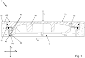
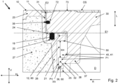
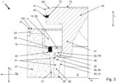
- Fig. 1 shows a longitudinal section through a manhole cover 1, the manhole cover 30 of which is arranged in a closed position PV. An enlarged section of this is the Fig. 2 Deviating from Fig. 2 the manhole cover 30 is in Fig. 3 arranged in a relief position PE.
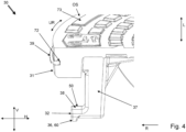
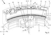
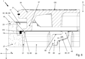
- the Fig. 4 and 5 contain three-dimensional detailed views of the manhole cover 30 and the manhole frame 10. According to the longitudinal section according to Fig. 6 the manhole cover 30 is arranged at a pre-positioning height PZ.
- the Fig. 7 is a top view of the manhole cover 1 of the Fig. 1 can be found.
- the manhole cover 1 has a manhole frame 10 and a manhole cover 30.
- a flush upper surface OS is formed by the shaft frame 10 and the shaft cover 30.
- the shaft frame 10 forms a shaft passage D running in a longitudinal direction L, which can be closed or is closed by positioning the shaft cover 30 on a cover receptacle 11 of the shaft frame 10 as shown.
- the shaft cover 30 is designed in particular to be insertable into the cover receptacle 11.
- a guide 40 is formed, which causes the shaft cover 30 to rotate by an angle of rotation (cf. reference number W in Fig. 5 and 7 ) into the Fig. 1 and 2 shown locking position PV.
- the shaft cover 30 and the cover holder 11 are circular in shape so that the manhole cover 30 can be rotated even in a relatively low position.
- the manhole cover 30 is designed to be surface watertight. Alternatively, however, it could also be equipped with through holes, e.g. for drainage. Furthermore, the manhole cover 30 is here formed as a single piece from cast iron. Alternatively, a design from cast iron and a filling material such as a concrete material is also possible. The manhole cover 30 should preferably be designed in a heavy-duty version for use in road construction. On the upper side OS of the manhole cover 30, fastening geometries 70 for a lifting device are formed, which in particular are again in Fig. 7 can be seen from a different perspective.
- the shaft frame 10 has a horizontally aligned frame collar 23 on the upper side OS (reference number see Fig. 2 ), which surrounds the cover receptacle 11 and the manhole cover 30.
- Both the manhole cover 30 and the manhole frame 10 have a surface structure 73 on the upper side OS, in particular an anti-slip structure with a plurality of elevations (ridges) which have a height greater than or equal to 2 mm.
- the shaft frame 10 has a vertically aligned tubular frame skirt 21 in the lower area of the cover receptacle 11.
- the guide 40 has a lowering ramp 41 sloping in the circumferential direction UR, as can be seen in particular in the Fig. 5 and 6
- This lowering ramp 41 is designed to be non-self-locking due to a sufficiently large gradient, so that the manhole cover 30 rotates through the angle of rotation W into the closed position PV when lowered due to its own weight.
- lowering ramps 41 are arranged distributed in the circumferential direction UR of the manhole cover 1.
- These lowering ramps 41 are each of the same shape and, as shown in the Fig. 5 and 6
- a Z-shaped course which consists of a gently sloping middle section 47 and two steeply sloping end sections.
- One of the end sections is a vertical entry section 45, which in the direction of rotation forms a rotation stop against screwing in.
- the other of the end sections is a vertical securing section 46, which lies in the rotation angle W of the locking position PV and forms rotation stops in the screwing-in direction (see reference number DR in Fig. 5 , 6 , 8 , 9 ) and opposite thereto.
- the more gently sloping central section 47 rotates the manhole cover 30 from the access section 45 into the securing section 46. In order to be able to remove it again from here, the manhole cover 30 must first be lifted slightly and can then be rotated back to the access section 45.
- the guide 40 consists of four active pairs P1 distributed over the circumference 31 of the manhole cover 30, wherein the active pairs P1 each have a sliding element 32 on the manhole cover 30 and one of the lowering ramps 41 on the cover receptacle 11.
- the sliding elements 32 are guided on the lowering ramp 41 in such a way that the manhole cover 30 rotates into the closed position PV when lowered by the rotation angle W in the screwing-in direction (DR).
- the manhole cover 30 Due to the four active pairs P1 arranged evenly over the circumference 31 of the manhole cover 30, the manhole cover 30 is secured against tilting from the horizontal H when lowered along the lowering ramp 41 and can be lowered into the locking position PZ at four different angles of rotation, i.e., rotated by 90 degrees each.
- designs with at least one or two, in particular with one, two, three, four, five, or six active pairs are also possible.
- the angle of rotation W should be at least 3 degrees, preferably at least 6 degrees, and particularly preferably at least 10 degrees. Furthermore, the angle of rotation W should be at most 100 degrees, preferably at most 30 degrees, and particularly preferably at most 14 degrees. In the exemplary embodiment, the angle of rotation is 12 degrees.
- one of the sliding elements 32 is formed by an L-shaped foot 37, which is arranged on the underside of the manhole cover 30 and points outwards with the free leg 38.
- the sliding element 32 has a sliding runner 36, which is at least three times as long in the circumferential direction UR of the manhole cover 1 as it is wide in the radial direction R.
- the other three sliding elements (not shown) are designed with the same shape as the illustrated sliding element 32.
- the manhole cover 30 in the closed position PV lies relatively loosely in the cover receptacle 11 despite the guide 40.
- the guide 40 has upward and downward play for vertical movements of the manhole cover 30 in the cover receptacle 11.
- the manhole cover 30 sits with the sliding elements 32 neither below, nor do the sliding elements 32 strike anywhere above.
- the guide 40 in the closed position PV has a vertically aligned free relief space XA below the sliding element 32 (see Fig. 2 ), so that the guide 40 does not absorb any vertically acting traffic loads acting on the manhole cover 30.
- a circumferential sealing ring 19 is arranged between the manhole cover 30 and the cover receptacle 11, via which sealing ring 19 the manhole cover 30 is supported on the cover receptacle 11 such that the sealing ring 19 bears the entire weight of the manhole cover 30.
- the sealing ring 19 is arranged in a horizontal parting plane E1 between the manhole cover 30 and the cover receptacle 11, where it sits in a receiving groove 20 of the manhole frame 10.
- the receiving groove 20 is formed in a horizontal support surface 24 of the cover receptacle 11, which is formed by a step arranged lower than the upper side OS.
- the support surface 24 comes into contact with the manhole cover 30 and part of the load is diverted past the sealing ring 19 into the manhole frame 10.
- the projection of the sealing ring 19 beyond the support surface 24 is smaller than the free relief clearance XA, so that even with a more compressed sealing ring 19, no traffic loads are transferred via the sliding elements 32.
- a secondary seal 39 with a sealing lip is arranged, which is seated in an outwardly facing receiving groove 72 of the manhole cover 30 and is arranged closer to the upper side OS of the manhole cover 1 than the sealing ring 19.
- the shaft cover 30 is secured in the rotation angle W of the locking position PV by a lifting stop 50 against linear movement out of the cover receptacle 11 in the longitudinal direction L without turning back by the rotation angle W.
- the guide 40 in the locking position PV forms a vertically aligned free lifting space XH above the sliding element 32 (see Fig. 2 ) and the lifting stop 50.
- the manhole cover 30 can thus be lifted within the lifting clearance XH and with the sliding element 32 up to the lifting stop 50.
- the contact surface of the manhole cover 30 to the sealing ring 19 is thereby - as can be seen in Fig. 3 sees - raised above the upper side OS of the shaft frame 10. In this way, the guide 40 leaves space for a pressure drop, so that the shaft cover 30 can be partially lifted out of the shaft frame 10 for venting or to drain water.
- the lifting stop 50 is aligned horizontally (see in particular Fig. 5 and 6 ), so that on the one hand the lifting movement does not cause the shaft cover 30 to be unscrewed in the opposite direction to the screwing in, and on the other hand does not cause the shaft cover 30 to be screwed in further and does not cause a rotation lock and/or rotation inhibition.
- the sliding element 32 can be rotated back along the lifting stop 50.
- a groove-shaped guide slot is formed between the lifting stop 50 and the lowering ramp 41, the flanks of which, however, do not run parallel to one another.
- the manhole cover 30 assumes a pre-positioning height PZ.
- pre-positioning means 60 are formed between the manhole cover 30 and the cover receptacle 11, which pre-positioning means correspond in such a way that the manhole cover 30 can initially be pre-centered and placed in the cover receptacle 11 at this pre-positioning height PZ, which is higher than the closed position PV. In particular, it is also higher than the relief position PE.
- the pre-positioning means 60 are also designed such that the pre-centered manhole cover 30 is centered and, guided by the pre-positioning means 60, can be rotated in a horizontal plane into the vertical entry sections of the guide 40 or a lowering position, from where it can be lowered further.
- the pre-positioning means 60 comprise circular segment-shaped guide track sections 12, 13 on the cover receptacle 11, which are formed by grooves in the step of the support surface 24 (see in particular Fig. 5 and 7 ).
- These guideway sections 12, 13 each open into recesses 26 in an inner surface 25 of the manhole frame 10, with the lowering ramps 41 each defining a side surface of one of the recesses 26.
- the manhole cover 30 is thus rotated with the aid of the pre-positioning means 60 until the sliding elements 32 fall into the recesses 26.
- the sliding elements 32 each form one of the pre-positioning means 60, for which purpose the sliding skids 36 engage in the guideway sections 12, 13.
- the sealing ring 19 surrounds the pre-positioning means 60 by having a larger radius than these.
- the manhole cover 30 protrudes according to Fig. 6 at the pre-positioning height PZ relatively far upwards out of the shaft frame 10, so that the fitter still has a largely clear view of the pre-positioning means 60 for pre-positioning.
- Fig. 7 As can be seen especially in Fig. 7 As can be seen, four release openings 22 for levering up the manhole cover 30 are formed in the upper side OS of the manhole cover 1 in the area between the manhole frame 10 and the manhole cover 30. For this purpose, there is a lever edge 71 on the manhole cover 30, which can be gripped under with a lever tool inserted into the release opening 22.
- the lifting stop 50 is aligned horizontally.
- the manhole cover 30 is loaded with a torque about the longitudinal axis L.
- the lifting stop 50 can be designed to rise (ie, relative to the horizontal) in such a way that it does not rotate in the opposite direction of rotation DR. Rather, it rotates in the direction of rotation DR, provided that it rotates slightly at all.
- the lifting stop 50 is equipped with a downwardly extending locking lug 51, which forms a rotation stop. This is shown in combination with an otherwise horizontal lifting stop 50. Combinations of the rotation stop with an ascending lifting stop 50 are also possible, as in Fig. 8 shown or, conversely, a sloping lifting stop 50, which promotes active unscrewing up to the rotation stop. This allows the sliding elements 32 to be positioned over the lowering ramps 41, and the manhole cover 30 lowers harmoniously again over the lowering ramps 41 once the pressure drop has passed.
- the lifting stop 50 is available in all variants shown. Fig. 6 , 8 and 9 designed so that it does not prevent lowering back into the closed position PV. If the manhole cover 30 rotates at all in the event of pressure (e.g., due to escaping water being set in rotation), the lifting stop 50 should be designed so that it does not prevent it from returning or rotating back into the closed position.
- a shaft structure with a shaft having an upper shaft opening is possible, wherein the shaft opening is covered with the illustrated shaft cover 1, and wherein the upper side OS of the shaft cover 1 is arranged at least substantially flush with a traffic area.
Landscapes
- Engineering & Computer Science (AREA)
- Environmental & Geological Engineering (AREA)
- Life Sciences & Earth Sciences (AREA)
- General Life Sciences & Earth Sciences (AREA)
- Mining & Mineral Resources (AREA)
- Paleontology (AREA)
- Civil Engineering (AREA)
- General Engineering & Computer Science (AREA)
- Structural Engineering (AREA)
- Underground Structures, Protecting, Testing And Restoring Foundations (AREA)
Priority Applications (1)
| Application Number | Priority Date | Filing Date | Title |
|---|---|---|---|
| EP23202678.1A EP4538464A1 (fr) | 2023-10-10 | 2023-10-10 | Couvercle de regard |
Applications Claiming Priority (1)
| Application Number | Priority Date | Filing Date | Title |
|---|---|---|---|
| EP23202678.1A EP4538464A1 (fr) | 2023-10-10 | 2023-10-10 | Couvercle de regard |
Publications (1)
| Publication Number | Publication Date |
|---|---|
| EP4538464A1 true EP4538464A1 (fr) | 2025-04-16 |
Family
ID=88315524
Family Applications (1)
| Application Number | Title | Priority Date | Filing Date |
|---|---|---|---|
| EP23202678.1A Pending EP4538464A1 (fr) | 2023-10-10 | 2023-10-10 | Couvercle de regard |
Country Status (1)
| Country | Link |
|---|---|
| EP (1) | EP4538464A1 (fr) |
Cited By (1)
| Publication number | Priority date | Publication date | Assignee | Title |
|---|---|---|---|---|
| CN121556506A (zh) * | 2026-01-21 | 2026-02-24 | 厦门赛茵泰科工程研究院有限公司 | 一种路面施工多功能井盖以及施工方法 |
Citations (5)
| Publication number | Priority date | Publication date | Assignee | Title |
|---|---|---|---|---|
| FR2339023A2 (fr) * | 1976-01-20 | 1977-08-19 | Sambre & Meuse Usines | Tampon pour regard circulaire et regard muni de ce tampon |
| DE3112641A1 (de) * | 1980-04-04 | 1982-04-29 | Pont-à-Mousson S.A., 54017 Nancy | Strassen-gully-ausbildung |
| DE3141006A1 (de) * | 1980-10-17 | 1982-05-19 | Pont-à-Mousson S.A., 54017 Nancy | Strassengullyausbildung |
| DE9302356U1 (de) * | 1993-02-15 | 1993-04-01 | Guß- und Armaturwerk Kaiserslautern Nachf. Karl Billand GmbH & Co, 6750 Kaiserslautern | Schachtabdeckung |
| EP2045398A2 (fr) | 2007-08-22 | 2009-04-08 | Buderus Kanalguss GmbH | Couvercle d'un regard d'égout avec "blocage de reflux" doté d'une fermeture rotative automatique pour éviter une sortie d'eaux usées par reflux |
-
2023
- 2023-10-10 EP EP23202678.1A patent/EP4538464A1/fr active Pending
Patent Citations (5)
| Publication number | Priority date | Publication date | Assignee | Title |
|---|---|---|---|---|
| FR2339023A2 (fr) * | 1976-01-20 | 1977-08-19 | Sambre & Meuse Usines | Tampon pour regard circulaire et regard muni de ce tampon |
| DE3112641A1 (de) * | 1980-04-04 | 1982-04-29 | Pont-à-Mousson S.A., 54017 Nancy | Strassen-gully-ausbildung |
| DE3141006A1 (de) * | 1980-10-17 | 1982-05-19 | Pont-à-Mousson S.A., 54017 Nancy | Strassengullyausbildung |
| DE9302356U1 (de) * | 1993-02-15 | 1993-04-01 | Guß- und Armaturwerk Kaiserslautern Nachf. Karl Billand GmbH & Co, 6750 Kaiserslautern | Schachtabdeckung |
| EP2045398A2 (fr) | 2007-08-22 | 2009-04-08 | Buderus Kanalguss GmbH | Couvercle d'un regard d'égout avec "blocage de reflux" doté d'une fermeture rotative automatique pour éviter une sortie d'eaux usées par reflux |
Cited By (1)
| Publication number | Priority date | Publication date | Assignee | Title |
|---|---|---|---|---|
| CN121556506A (zh) * | 2026-01-21 | 2026-02-24 | 厦门赛茵泰科工程研究院有限公司 | 一种路面施工多功能井盖以及施工方法 |
Similar Documents
| Publication | Publication Date | Title |
|---|---|---|
| DE69000686T2 (de) | Wagenparkanlage fuer individuelles und automatisches parken im stadtbereich. | |
| EP2890625A1 (fr) | Système de rail | |
| EP0986689A1 (fr) | Dispositif pour empecher le passage | |
| AT517351B1 (de) | Notfallöffnungsleitwandelement | |
| DE69707258T2 (de) | Gerät zum Anbringen von Deckplatten | |
| EP4538464A1 (fr) | Couvercle de regard | |
| DE2501435A1 (de) | Vorrichtung zum verriegeln eines deckels eines strassenschachtes | |
| EP1355009A2 (fr) | Dispositif de recouvrement pour joints | |
| DE3714053C2 (de) | Aufzug für Personentransport | |
| EP3272943A1 (fr) | Porte barrière d'eau coulissante | |
| DE202017100539U1 (de) | Schachtabdeckung | |
| DE69204526T2 (de) | Drehbare Durchfahrtsperre. | |
| EP4087997B1 (fr) | Dispositif de stationnement équipé d'un ensemble de porte | |
| DE60025597T2 (de) | Strassenbaueinrichtung | |
| DE102019124672B3 (de) | Dreheinheit für einen um seine Hochachse rotierbaren Fahrzeugsitz, Crashhaken für eine solche Dreheinheit und rotierbarer Fahrzeugsitz | |
| EP0960849A2 (fr) | Dispositif de levage, en particulier pont de levage pour véhicules | |
| EP0120218B1 (fr) | Couvercle pour vannes de tuyaux souterrains | |
| DE3587789T2 (de) | Gewindeverstellvorrichtung. | |
| EP4253709A1 (fr) | Seuil de porte | |
| DE2162996C3 (de) | Schachtabdeckung für einen Einsteigschacht in einer Straße o.dgl | |
| AT522089B1 (de) | Höhenverstellbares Schachtringelement | |
| DE19609602A1 (de) | Wasserübergabeschacht mit kunststoffhaltigen Segmenten | |
| DE60010256T2 (de) | Vorrichtung zur verriegelung eines abdeckelementes auf einem stützrahmen | |
| CH630699A5 (de) | Drehkreuz mit richtungsbezogener sperre zur bildung eines durchlasses in umzaeunungen, gittern oder anderen absperrungen. | |
| CH702820A2 (de) | Aushängegelenk sowie Schachtabdeckung. |
Legal Events
| Date | Code | Title | Description |
|---|---|---|---|
| PUAI | Public reference made under article 153(3) epc to a published international application that has entered the european phase |
Free format text: ORIGINAL CODE: 0009012 |
|
| STAA | Information on the status of an ep patent application or granted ep patent |
Free format text: STATUS: THE APPLICATION HAS BEEN PUBLISHED |
|
| AK | Designated contracting states |
Kind code of ref document: A1 Designated state(s): AL AT BE BG CH CY CZ DE DK EE ES FI FR GB GR HR HU IE IS IT LI LT LU LV MC ME MK MT NL NO PL PT RO RS SE SI SK SM TR |
|
| STAA | Information on the status of an ep patent application or granted ep patent |
Free format text: STATUS: REQUEST FOR EXAMINATION WAS MADE |
|
| 17P | Request for examination filed |
Effective date: 20250701 |