EP4538466A1 - Système de changement rapide et adaptateur pour un tel système de changement rapide - Google Patents
Système de changement rapide et adaptateur pour un tel système de changement rapide Download PDFInfo
- Publication number
- EP4538466A1 EP4538466A1 EP24195140.9A EP24195140A EP4538466A1 EP 4538466 A1 EP4538466 A1 EP 4538466A1 EP 24195140 A EP24195140 A EP 24195140A EP 4538466 A1 EP4538466 A1 EP 4538466A1
- Authority
- EP
- European Patent Office
- Prior art keywords
- locking
- quick
- adapter
- change system
- elements
- Prior art date
- Legal status (The legal status is an assumption and is not a legal conclusion. Google has not performed a legal analysis and makes no representation as to the accuracy of the status listed.)
- Pending
Links
Images

Classifications
-
- E—FIXED CONSTRUCTIONS
- E02—HYDRAULIC ENGINEERING; FOUNDATIONS; SOIL SHIFTING
- E02F—DREDGING; SOIL-SHIFTING
- E02F3/00—Dredgers; Soil-shifting machines
- E02F3/04—Dredgers; Soil-shifting machines mechanically-driven
- E02F3/28—Dredgers; Soil-shifting machines mechanically-driven with digging tools mounted on a dipper- or bucket-arm, i.e. there is either one arm or a pair of arms, e.g. dippers, buckets
- E02F3/36—Component parts
- E02F3/3604—Devices to connect tools to arms, booms or the like
- E02F3/3609—Devices to connect tools to arms, booms or the like of the quick acting type, e.g. controlled from the operator seat
- E02F3/365—Devices to connect tools to arms, booms or the like of the quick acting type, e.g. controlled from the operator seat with redundant latching means, e.g. for safety purposes
-
- E—FIXED CONSTRUCTIONS
- E02—HYDRAULIC ENGINEERING; FOUNDATIONS; SOIL SHIFTING
- E02F—DREDGING; SOIL-SHIFTING
- E02F3/00—Dredgers; Soil-shifting machines
- E02F3/04—Dredgers; Soil-shifting machines mechanically-driven
- E02F3/28—Dredgers; Soil-shifting machines mechanically-driven with digging tools mounted on a dipper- or bucket-arm, i.e. there is either one arm or a pair of arms, e.g. dippers, buckets
- E02F3/36—Component parts
- E02F3/3604—Devices to connect tools to arms, booms or the like
- E02F3/3609—Devices to connect tools to arms, booms or the like of the quick acting type, e.g. controlled from the operator seat
- E02F3/3618—Devices to connect tools to arms, booms or the like of the quick acting type, e.g. controlled from the operator seat with two separating hooks
-
- E—FIXED CONSTRUCTIONS
- E02—HYDRAULIC ENGINEERING; FOUNDATIONS; SOIL SHIFTING
- E02F—DREDGING; SOIL-SHIFTING
- E02F3/00—Dredgers; Soil-shifting machines
- E02F3/04—Dredgers; Soil-shifting machines mechanically-driven
- E02F3/28—Dredgers; Soil-shifting machines mechanically-driven with digging tools mounted on a dipper- or bucket-arm, i.e. there is either one arm or a pair of arms, e.g. dippers, buckets
- E02F3/36—Component parts
- E02F3/3604—Devices to connect tools to arms, booms or the like
- E02F3/3609—Devices to connect tools to arms, booms or the like of the quick acting type, e.g. controlled from the operator seat
- E02F3/3622—Devices to connect tools to arms, booms or the like of the quick acting type, e.g. controlled from the operator seat with a hook and a locking element acting on a pin
-
- E—FIXED CONSTRUCTIONS
- E02—HYDRAULIC ENGINEERING; FOUNDATIONS; SOIL SHIFTING
- E02F—DREDGING; SOIL-SHIFTING
- E02F3/00—Dredgers; Soil-shifting machines
- E02F3/04—Dredgers; Soil-shifting machines mechanically-driven
- E02F3/28—Dredgers; Soil-shifting machines mechanically-driven with digging tools mounted on a dipper- or bucket-arm, i.e. there is either one arm or a pair of arms, e.g. dippers, buckets
- E02F3/36—Component parts
- E02F3/3604—Devices to connect tools to arms, booms or the like
- E02F3/3686—Devices to connect tools to arms, booms or the like using adapters, i.e. additional element to mount between the coupler and the tool
Definitions
- the quick coupler has, for example, claw-shaped first receptacles on one side for holding a first coupling element arranged on the adapter, and second receptacles on the other side with at least one locking element movable between a release position and a locking position for releasably holding a second coupling element arranged on the adapter.
- a generic quick-change system comprises a quick-change system that has claw-shaped first receptacles for a first coupling element on one side of a carrier and second receptacles on the other side of the carrier with at least one locking element movable between a release position and a locking position for releasably holding a second coupling element.
- An adapter belonging to the quick-change system has two bolt-shaped coupling elements arranged between parallel sidecars at a predetermined distance from one another for connecting the adapter to the quick-change system.
- the object of the invention is therefore to provide a quick-change system and an adapter for such a quick-change system, in which an unintentional detachment of the adapter from a quick-change device can be avoided and thus safety can be increased.
- the adapter has coupling elements arranged between two side walls at a predetermined distance from one another, and the quick-change coupler has a carrier, first receptacles arranged on one side of the carrier for receiving the first coupling element, second receptacles arranged on the other side of the carrier for receiving the second coupling element, and a locking device with at least one locking element that can be moved between a release position and a locking position by means of a drive for lockingly holding the second bolt-shaped coupling element on the second receptacles.
- the quick-change system is characterized by a mechanical safety device that interacts with the locking device of the quick-change coupler and contains at least one locking element that can be moved into a locking position for blocking the at least one locking element in the locking position.
- the mechanical safety device can contain two interconnected locking elements which can be moved between the locking position for blocking two bolt-shaped locking elements in an extended locking position and a release position which enables the displacement of the two bolt-shaped locking elements between the extended locking position and a retracted release position.
- the mechanical safety device is preferably integrated into the adapter. However, it could also be located in the quick coupler or be designed as a separate unit that can be inserted as needed.
- the invention also relates to an adapter for a quick-change system for changing attachments on a construction machine, which adapter contains coupling elements arranged between two side walls at a predetermined distance from one another for coupling to a quick-change device provided with a locking device and a mechanical safety device which has at least one locking element movable on the inside of a side wall between a lowered release position and a raised locking position for blocking at least one locking element of the locking device.
- the two locking elements are conveniently located on actuating elements that protrude through slot-shaped openings in the side walls and protrude outward from the side walls. This allows the locking elements to be moved manually from the release to the locked position even if the adapter is not accessible from below due to a base plate or an attachment attached to the adapter.
- the position of the locking elements is also easily recognizable from the outside via the actuating elements that protrude outward from the side walls.
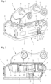
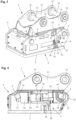
- the quick coupler 1 which can be mounted, for example, on a boom of an excavator, contains a carrier 10 with two parallel side parts 11, in which continuous receiving openings 12 for fastening bolts 13 are provided for fastening the quick coupler 1 to a boom of an excavator or a connecting part of another construction vehicle.
- the quick coupler 1 has, on one side of the carrier 10, claw-shaped or fork-shaped first receptacles 14, which are open towards the front, for receiving and holding the first bolt-shaped coupling element 5, and, on the other side, second receptacles 15, which are open towards the rear and downwards, for receiving the second bolt-shaped coupling element 6. Also provided on the quick coupler 1 is a locking device 16 with two locking elements 17, which can be moved by means of a drive between a release position and a locking position, for lockingly holding the second bolt-shaped coupling element 6.
- the locking elements 17 consist of two locking bolts parallel to one another, which are guided displaceably in guide bores within the carrier 10 and can be moved by a drive between a retracted release position and a Figure 2 In the extended locking position shown in Figure 2 In the extended locking position shown in Figure 2 In the extended locking position shown, the downwardly open second receptacles 15 are closed by the bolt-shaped locking elements 16 on the underside, so that the second bolt-shaped coupling element 6 is engaged under by the bolt-shaped locking elements 16 and the adapter 2 can be held on the quick coupler 1.
- two bolt-shaped locking elements 17 only one locking element could be provided.
- the drive, referred to as the H-cylinder, for displacing the locking element 17 of the locking device is designed as a hydraulic cylinder-piston drive with two hydraulic pistons arranged within an H-shaped housing 18.
- the H-shaped housing 18 contains two parallel outer parts 20 connected to one another via a central part 19, in which pressure chambers are arranged for accommodating two parallel hydraulic pistons with outwardly projecting piston rods 21.
- Figure 2 one of the piston rods 21 of the hydraulic pistons arranged in the two outer parts 20 of the housing 10 is shown.
- a bolt-shaped locking element 17 is arranged for the locking retention of the second coupling element 6.
- the piston rods 21 are fixed with their free outer ends to the support 10, so that the H-shaped housing 18 with the bolt-shaped locking elements 16 arranged thereon can be locked by appropriate pressure application to the pressure chambers arranged within the two outer parts 20 of the housing 18 between the Figure 2 shown locking position and a retracted release or change position.
- the bolt-shaped locking elements 16 are extended and engage under the second bolt-shaped coupling element 6 to lock the adapter 2.
- a mechanical fall protection device is provided on the adapter 2.
- the fall protection device is designed to engage the coupling element 5 arranged on the adapter 2 or the attachment and engaging with the first receptacles 14.
- a nose-shaped control element 24 is arranged on the catch hook 22, which interacts with the coupling element 5 on the adapter 2 and pivots the catch hook 22 between the folded-down change and catch position and the folded-up safety position, independent of the locking device.
- a reset device arranged on the carrier pushes the catch hook 22 into its folded-down change and catch position. This ensures that the catch hook 22 is securely in its folded-down change and catch position when the attachment is not yet coupled, regardless of the position of the quick coupler 1.
- an attachment In the folded-down change and catch position of the catch hooks 22, an attachment can be changed by placing it on the ground accordingly and, if necessary, can be caught in a catch position by engagement of the coupling element 5 on the catch hooks 22 and thus held on the quick coupler 1, while the catch hooks 22 completely enclose the receptacles 14 for the coupling element 5 in the folded-up securing position.
- the adapter 2 is shown with the mechanical safety device 9 in a lowered release position and a raised locking position.
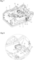
- the mechanical safety device 9 contains two parallel clamp-shaped locking elements 25, which are arranged on the inside of the two side walls 4 between a Figures 5 and 6 shown lowered release position and one in the Figures 7 and 8
- the two locking elements 25, which are U-shaped in cross section, are designed in such a way that in the raised locking position they can be moved over the two Piston rods 21 engage and can be pushed between the carrier 10 and the housing 18 of the drive. This prevents displacement of the housing 18 with the bolt-shaped locking elements 17 arranged thereon into a retracted release or change position. In the raised securing position, the two locking elements 25 thus block the housing 18 with the locking elements 17 arranged thereon in the locking position. This prevents unintentional opening of the quick coupler 1 and securely holds a properly coupled adapter 2 to the quick coupler 1.
- the two clamp-shaped locking elements 25 are arranged on angular actuating elements 27 which protrude through slot-shaped openings 26 in the side cheeks 4 of the adapter 2 and project outwards relative to the side cheeks 4.
- the two actuating elements 27 have angular outer parts 28 which project outwards relative to the side cheeks 4 and are connected to one another by a connecting rod 29. Via the angular outer parts 28 of the actuating elements 27, the locking elements 25 can be manually removed from the Figure 8 shown raised locking position against the force of a spring arrangement 30 into the Figure 6 shown lowered release position must be pressed.
- a Figure 1 visible through-bore 31 is provided for the insertion of a locking pin 32.
- a locking pin 32 To the right and left of the outer part 28, on the outside of the two side cheeks 4, outwardly projecting retaining webs 33 and 34 are arranged, with upper and lower through-bores 35 and 36 for the insertion of the locking pin 32.
- the locking pin 32 and the retaining webs 33 and 34 form a locking device for securing the two locking elements 25 both in the lowered release position and in the raised locking position.
- the locking pin 32 can be secured by a locking pin 37 designed as a spring pin.
- the locking pin 32 and the locking pin 37 can be secured against loss with a wire rope on the adapter 2.
Landscapes
- Engineering & Computer Science (AREA)
- Mechanical Engineering (AREA)
- Mining & Mineral Resources (AREA)
- Civil Engineering (AREA)
- General Engineering & Computer Science (AREA)
- Structural Engineering (AREA)
- Quick-Acting Or Multi-Walled Pipe Joints (AREA)
- Earth Drilling (AREA)
- Shovels (AREA)
- Component Parts Of Construction Machinery (AREA)
Applications Claiming Priority (1)
| Application Number | Priority Date | Filing Date | Title |
|---|---|---|---|
| DE102023127568.2A DE102023127568A1 (de) | 2023-10-10 | 2023-10-10 | Schnellwechselsystem und adapter für ein derartiges schnellwechselsystem |
Publications (1)
| Publication Number | Publication Date |
|---|---|
| EP4538466A1 true EP4538466A1 (fr) | 2025-04-16 |
Family
ID=92459208
Family Applications (1)
| Application Number | Title | Priority Date | Filing Date |
|---|---|---|---|
| EP24195140.9A Pending EP4538466A1 (fr) | 2023-10-10 | 2024-08-19 | Système de changement rapide et adaptateur pour un tel système de changement rapide |
Country Status (7)
| Country | Link |
|---|---|
| US (1) | US20250116081A1 (fr) |
| EP (1) | EP4538466A1 (fr) |
| JP (1) | JP2025066090A (fr) |
| CN (1) | CN119801070A (fr) |
| AU (1) | AU2024227046B2 (fr) |
| CA (1) | CA3250334A1 (fr) |
| DE (1) | DE102023127568A1 (fr) |
Citations (4)
| Publication number | Priority date | Publication date | Assignee | Title |
|---|---|---|---|---|
| US8782931B2 (en) * | 2009-12-09 | 2014-07-22 | S T Couplers Limited | Couplers |
| DE102018128479A1 (de) | 2018-11-14 | 2020-05-14 | Oilquick Deutschland Gmbh | Schnellwechsler und Schnellwechselsystem mit einem derartigen Schnellwechsler |
| DE102020127481B3 (de) * | 2020-10-19 | 2021-04-15 | Béla Cseri Besitzunternehmung GbR (vertretungsberechtigter Gesellschafter: Béla Cseri, 89129 Langenau) | Schnellwechsler mit Sperrklappe |
| DE102020121067A1 (de) * | 2020-08-11 | 2022-02-17 | emtec Engineering & Maschinentechnik GmbH | Verbindungsvorrichtung zum Ankuppeln eines Anbaugerätes an eine Arbeitsvorrichtung und Arbeitsvorrichtung |
Family Cites Families (8)
| Publication number | Priority date | Publication date | Assignee | Title |
|---|---|---|---|---|
| US4297074A (en) * | 1980-01-07 | 1981-10-27 | Ballinger Paul V | Demountable interconnection |
| DE9000721U1 (de) * | 1990-01-24 | 1990-03-01 | Nagler, Jürgen, 5804 Herdecke | Schnellkupplung eines Arbeitsvorsatzes an Baggern |
| DE59800510D1 (de) * | 1997-04-14 | 2001-04-12 | Baumaschinentechnik Gmbh Villa | Schnellwechselvorrichtung für bagger |
| IT1310182B1 (it) * | 1999-03-02 | 2002-02-11 | Mantovanibenne S R L | Dispositivo per il bloccaggio e lo sbloccaggio rapidi di attrezzi abracci operatori. |
| JP2004132495A (ja) * | 2002-10-11 | 2004-04-30 | Furukawa Co Ltd | 建設車両のシリンダ用ストッパ |
| WO2007068043A1 (fr) * | 2005-12-12 | 2007-06-21 | Positti, Nicole, Elizabeth | Dispositif de sécurité pour ensemble d’attelage hydraulique |
| JP2010059714A (ja) * | 2008-09-04 | 2010-03-18 | Yanmar Co Ltd | リフトアームの固定構造 |
| DE102016014905B3 (de) * | 2016-12-15 | 2018-02-15 | Markus Riedlberger | Werkzeugadapter mit einer Vorrichtung zur Verriegelungskontrolle einer Schnellwechselvorrichtung für Baugeräte |
-
2023
- 2023-10-10 DE DE102023127568.2A patent/DE102023127568A1/de active Pending
-
2024
- 2024-08-19 EP EP24195140.9A patent/EP4538466A1/fr active Pending
- 2024-09-11 CA CA3250334A patent/CA3250334A1/fr active Pending
- 2024-09-19 US US18/889,515 patent/US20250116081A1/en active Pending
- 2024-09-30 CN CN202411381374.2A patent/CN119801070A/zh active Pending
- 2024-10-02 AU AU2024227046A patent/AU2024227046B2/en active Active
- 2024-10-09 JP JP2024177027A patent/JP2025066090A/ja active Pending
Patent Citations (4)
| Publication number | Priority date | Publication date | Assignee | Title |
|---|---|---|---|---|
| US8782931B2 (en) * | 2009-12-09 | 2014-07-22 | S T Couplers Limited | Couplers |
| DE102018128479A1 (de) | 2018-11-14 | 2020-05-14 | Oilquick Deutschland Gmbh | Schnellwechsler und Schnellwechselsystem mit einem derartigen Schnellwechsler |
| DE102020121067A1 (de) * | 2020-08-11 | 2022-02-17 | emtec Engineering & Maschinentechnik GmbH | Verbindungsvorrichtung zum Ankuppeln eines Anbaugerätes an eine Arbeitsvorrichtung und Arbeitsvorrichtung |
| DE102020127481B3 (de) * | 2020-10-19 | 2021-04-15 | Béla Cseri Besitzunternehmung GbR (vertretungsberechtigter Gesellschafter: Béla Cseri, 89129 Langenau) | Schnellwechsler mit Sperrklappe |
Also Published As
| Publication number | Publication date |
|---|---|
| JP2025066090A (ja) | 2025-04-22 |
| DE102023127568A1 (de) | 2025-04-10 |
| AU2024227046A1 (en) | 2025-04-24 |
| CA3250334A1 (fr) | 2025-06-04 |
| AU2024227046B2 (en) | 2026-01-22 |
| US20250116081A1 (en) | 2025-04-10 |
| CN119801070A (zh) | 2025-04-11 |
Similar Documents
| Publication | Publication Date | Title |
|---|---|---|
| EP3653796B1 (fr) | Dispositif de changement rapide et système de changement rapide doté d'un tel dispositif de changement rapide | |
| DE3312442C2 (de) | Schnellwechselvorrichtung für Arbeitswerkzeuge an einem Baggerausleger | |
| EP3591122B1 (fr) | Système de changement rapide | |
| DE60106865T2 (de) | Universelle kupplung für baggerschaufel | |
| DE10297276T5 (de) | Aufsatzkopplungsvorrichtung für Schwermaschinen | |
| DE102017110586B4 (de) | Schnellwechsler und Schnellwechselsystem mit einem derartigen Schnellwechsler | |
| DE2926292A1 (de) | Insbesondere mobiler teleskopauslegerkran | |
| EP2018456A1 (fr) | Dispositif de changement rapide | |
| EP3502357B1 (fr) | Dispositif de changement rapide | |
| EP1522635B1 (fr) | Attache rapide pour fixer des outils sur un bras d'excavatrices | |
| EP3922774B1 (fr) | Adaptateur pour un système de changement rapide et système de changement rapide doté d'un tel adaptateur | |
| EP3730697B2 (fr) | Adaptateur pour un système de changement rapide et système de changement rapide doté d'un tel adaptateur | |
| DE202021100754U1 (de) | Schnellwechsler und Schnellwechselvorrichtung mit einem Schnellwechsler | |
| EP2159334B1 (fr) | Dispositif d'attache outil | |
| EP4310260B1 (fr) | Dispositif de changement rapide et système de changement rapide doté d'un tel dispositif de changement rapide | |
| EP4538466A1 (fr) | Système de changement rapide et adaptateur pour un tel système de changement rapide | |
| EP3517690B1 (fr) | Adaptateur, dispositif de changement rapide et système de changement rapide | |
| DE202022104056U1 (de) | Schnellwechsler und Schnellwechselsystem mit einem derartigen Schnellwechsler | |
| EP3901378A1 (fr) | Accouplement rapide pourvu de dispositif de centrage | |
| DE102019125861A1 (de) | Schnellwechsler | |
| DE202023105844U1 (de) | Schnellwechselsystem und Adapter für ein derartiges Schnellwechselsystem | |
| DE102015225498A1 (de) | Schnellwechselsystem mit mechanischer sicherheitseinrichtung gegen unbeabsichtigtes ablösen eines arbeitsgerätes | |
| DE19806057A1 (de) | Baumaschinenadapter | |
| AT2322U2 (de) | Schnellwechselvorrichtung für bagger mit verriegelungssicherung | |
| AT2087U1 (de) | Schnellwechselvorrichtung für bagger mit verriegelungsanzeige |
Legal Events
| Date | Code | Title | Description |
|---|---|---|---|
| PUAI | Public reference made under article 153(3) epc to a published international application that has entered the european phase |
Free format text: ORIGINAL CODE: 0009012 |
|
| STAA | Information on the status of an ep patent application or granted ep patent |
Free format text: STATUS: THE APPLICATION HAS BEEN PUBLISHED |
|
| AK | Designated contracting states |
Kind code of ref document: A1 Designated state(s): AL AT BE BG CH CY CZ DE DK EE ES FI FR GB GR HR HU IE IS IT LI LT LU LV MC ME MK MT NL NO PL PT RO RS SE SI SK SM TR |
|
| STAA | Information on the status of an ep patent application or granted ep patent |
Free format text: STATUS: REQUEST FOR EXAMINATION WAS MADE |
|
| 17P | Request for examination filed |
Effective date: 20250425 |