EP4538492A2 - Élément de cadre pour un système de mur et système de mur - Google Patents
Élément de cadre pour un système de mur et système de mur Download PDFInfo
- Publication number
- EP4538492A2 EP4538492A2 EP24203914.7A EP24203914A EP4538492A2 EP 4538492 A2 EP4538492 A2 EP 4538492A2 EP 24203914 A EP24203914 A EP 24203914A EP 4538492 A2 EP4538492 A2 EP 4538492A2
- Authority
- EP
- European Patent Office
- Prior art keywords
- frame part
- frame
- wall system
- window
- connection area
- Prior art date
- Legal status (The legal status is an assumption and is not a legal conclusion. Google has not performed a legal analysis and makes no representation as to the accuracy of the status listed.)
- Pending
Links
Images


Classifications
-
- E—FIXED CONSTRUCTIONS
- E04—BUILDING
- E04B—GENERAL BUILDING CONSTRUCTIONS; WALLS, e.g. PARTITIONS; ROOFS; FLOORS; CEILINGS; INSULATION OR OTHER PROTECTION OF BUILDINGS
- E04B2/00—Walls, e.g. partitions, for buildings; Wall construction with regard to insulation; Connections specially adapted to walls
- E04B2/88—Curtain walls
- E04B2/96—Curtain walls comprising panels attached to the structure through mullions or transoms
- E04B2/967—Details of the cross-section of the mullions or transoms
-
- E—FIXED CONSTRUCTIONS
- E06—DOORS, WINDOWS, SHUTTERS, OR ROLLER BLINDS IN GENERAL; LADDERS
- E06B—FIXED OR MOVABLE CLOSURES FOR OPENINGS IN BUILDINGS, VEHICLES, FENCES OR LIKE ENCLOSURES IN GENERAL, e.g. DOORS, WINDOWS, BLINDS, GATES
- E06B1/00—Border constructions of openings in walls, floors, or ceilings; Frames to be rigidly mounted in such openings
- E06B1/04—Frames for doors, windows, or the like to be fixed in openings
- E06B1/06—Wooden frames
-
- E—FIXED CONSTRUCTIONS
- E06—DOORS, WINDOWS, SHUTTERS, OR ROLLER BLINDS IN GENERAL; LADDERS
- E06B—FIXED OR MOVABLE CLOSURES FOR OPENINGS IN BUILDINGS, VEHICLES, FENCES OR LIKE ENCLOSURES IN GENERAL, e.g. DOORS, WINDOWS, BLINDS, GATES
- E06B3/00—Window sashes, door leaves, or like elements for closing wall or like openings; Layout of fixed or moving closures, e.g. windows in wall or like openings; Features of rigidly-mounted outer frames relating to the mounting of wing frames
- E06B3/04—Wing frames not characterised by the manner of movement
- E06B3/06—Single frames
- E06B3/08—Constructions depending on the use of specified materials
- E06B3/10—Constructions depending on the use of specified materials of wood
-
- E—FIXED CONSTRUCTIONS
- E06—DOORS, WINDOWS, SHUTTERS, OR ROLLER BLINDS IN GENERAL; LADDERS
- E06B—FIXED OR MOVABLE CLOSURES FOR OPENINGS IN BUILDINGS, VEHICLES, FENCES OR LIKE ENCLOSURES IN GENERAL, e.g. DOORS, WINDOWS, BLINDS, GATES
- E06B3/00—Window sashes, door leaves, or like elements for closing wall or like openings; Layout of fixed or moving closures, e.g. windows in wall or like openings; Features of rigidly-mounted outer frames relating to the mounting of wing frames
- E06B3/32—Arrangements of wings characterised by the manner of movement; Arrangements of movable wings in openings; Features of wings or frames relating solely to the manner of movement of the wing
- E06B3/34—Arrangements of wings characterised by the manner of movement; Arrangements of movable wings in openings; Features of wings or frames relating solely to the manner of movement of the wing with only one kind of movement
- E06B3/42—Sliding wings; Details of frames with respect to guiding
- E06B3/46—Horizontally-sliding wings
-
- E—FIXED CONSTRUCTIONS
- E06—DOORS, WINDOWS, SHUTTERS, OR ROLLER BLINDS IN GENERAL; LADDERS
- E06B—FIXED OR MOVABLE CLOSURES FOR OPENINGS IN BUILDINGS, VEHICLES, FENCES OR LIKE ENCLOSURES IN GENERAL, e.g. DOORS, WINDOWS, BLINDS, GATES
- E06B3/00—Window sashes, door leaves, or like elements for closing wall or like openings; Layout of fixed or moving closures, e.g. windows in wall or like openings; Features of rigidly-mounted outer frames relating to the mounting of wing frames
- E06B3/54—Fixing of glass panes or like plates
- E06B3/5427—Fixing of glass panes or like plates the panes mounted flush with the surrounding frame or with the surrounding panes
Definitions
- the invention relates to a frame part for a wall system according to claim 1 and a wall system according to claim 10.
- clamping elements are placed on frame-forming timber skeletons.
- the clamping elements hold surface components, such as glass panes, but also plasterboard and chipboard, frame frames for fixed frame windows, or as an attachment, casement windows, hinged doors, sliding windows, and sliding doors to form a wall laterally, even on both sides.
- a cover element is inserted on the outside of the clamping components to cover the clamping component.
- the entire building can be constructed in this way, or just parts of the building, in particular individual parts of exterior walls.
- the invention therefore sets itself the task of providing a wall system and frame components for the wall system to overcome the aforementioned difficulties and, above all, to keep installation and assembly costs low.
- a frame part for a wall system wherein the frame part comprises a main body and at least one connection area.
- the frame part is characterized in that it is designed as a single piece with the main body and the connection area.
- the basic idea of the invention is to provide a system for the surface component in the frame part and to additionally limit it laterally. This allows a simple way of A tight seal can be created along the surface of the surface component or frame component, while still allowing a certain amount of play between the surface component and the frame.
- the one-piece design also prevents water from penetrating between the main body and the connection area, and the individual components do not require complex on-site connection. Additionally, a flush seal can be created between the frame component and the surface component toward the exterior or interior wall.
- the frame part serves to form a frame for at least one surface component, preferably 2, 3, 4, 5, 6, 7, 8, 9, 10, 11, 12, 13, 14, 15, 16, 17, 18, 19, 20 or more identically or differently designed surface components of the wall system, in particular together with other frame parts, in order to frame this laterally, i.e. at the edge or edges of the surface component.
- the frame parts form a skeleton for the wall to be produced.
- the frame parts are particularly preferably aligned in the horizontal or vertical direction to form a frame and frame rectangular cutouts.
- any other geometry is possible; in particular, the frame parts can be curved.
- the frame part is usually designed to be elongated in one direction, in terms of height, but due to the geometry of the frame to be produced, one or more frame parts are designed to be short in height, in particular shorter than in the other dimensions.
- the main body of the frame component provides the necessary stability for the wall system frame to support the surface components, objects attached to the surface components, and the weight of the frame components.
- the main body it is conceivable to design the main body so solid that it is load-bearing.
- connection area offers the surface component at least one lateral and/or one rear contact surface and delimits it laterally and rearward.
- the frame part can preferably comprise at least 2, 3, 4, 5, 6, 7, 8, 9, 10, 11, 12, 13, 14, 15, 16, 17, 18, 19, 20 or more identically or differently designed connection areas. It is conceivable for two connection areas to be arranged on opposite sides of the frame part in the cross-section of the frame part. In this way, two surface components can be arranged essentially in one plane or at an angle to one another in the direction of the depth and/or in the direction of the width of the frame part. It is also conceivable for two connection areas to be arranged next to one another in the direction of the height of the frame part. Two surface components can then be arranged in the direction of the width.
- the surface component is held in place at the connection area by at least one retaining element.
- the retaining element can preferably be a clamping element or a hinge.
- the term "surface component" is known to a person skilled in the art and refers, for example, but by no means exclusively, to at least one glass pane, in particular in single, double, triple, or multiple glazing; a board, in particular a plasterboard, a multi-layer board, a composite board, a vacuum board, and/or a chipboard; a panel; a composite component; a frame for fixed framed windows; a frame as an attachment for a window, such as a casement window, a window sash, a hinged window, or a sliding window, in particular a lift-and-slide window; and/or a door, such as a hinged door, a door sash, a hinged door, or a sliding door, in particular a lift-and-slide door; a previously described window; a previously described door
- the one-piece frame part with the main body and the connection area forms a preferably tight connection with the surface component.
- at least one circumferential seal between the frame part and the surface component preferably 2, 3, 4, 5, 6, 7, 8, 9, 10 or more circumferential seals of the same or different designs.
- the seal is particularly preferably made of an elastic material. This allows for the compensation of manufacturing tolerances and/or different weather-related expansions of frame parts and surface components.
- the term "tight connection” or “sealing” describes a measure of the tightness of the frame component, including the main body and connection area, the surface component, and the wall system, relative to the environment, i.e., relative to an external influence, i.e., a substance, a fluid, and/or a mixture thereof.
- external influence refers, for example, but by no means exclusively, to all influences that damage the frame component, the surface component, the wall system, and/or the environment. Examples of such influences include fluids such as moisture and/or gases, dust particles, and/or other contaminants.
- sealing or tightness is a relative term and that there is no such thing as absolute sealing of the frame part, the surface component, and the wall system from the environment.
- sealing or tightness is therefore to be understood as always referring to predetermined, required and/or predefined framework conditions, so that the frame part, the surface component, and the wall system are reliably protected from external influences and their entry and/or penetration. It is understandable that the entry and/or penetration of external influences may be possible for a short time. The possibility of such a short-term and/or passage of external influence is of minor importance.
- the frame part, the surface component, and the wall system according to the invention do not have to be absolutely tight. Rather, it is preferred that the entry and/or passage of external influences is impeded as far as possible in order to prevent damage to the frame part, the surface component, and the wall system. Even more preferably, the entry and/or passage of external influences is completely impeded in one or both of the aforementioned directions, so that absolute tightness can be achieved at least partially and/or temporarily.
- the tightness can also be adapted through the structural design of the frame part, the surface component, and the wall system. However, this is associated with increased costs.
- the degree of sealing is at least 95%, 96%, 97%, 98%, 99%, 99.5%, 99.6%, 99.7%, 99.8%, 99.9% or more.
- the degree of sealing depends significantly on the material used, the location, the operating conditions, and/or the intended use of the frame component, the surface component, and the wall system. This is well known to a person skilled in the art.
- single-piece refers to the frame part's ability to consist of a single component. It means that the frame part cannot be disassembled into multiple parts and/or structures, or at least not without damage.
- width, depth, and height refer to a coordinate system related to the frame component. Height refers to the dimension that runs along the main axis of the frame component and is usually the longest dimension. Depth refers to the dimension that extends between the outside and inside of the future wall system. The width is the dimension that is orthogonal to both the depth and the height.
- load-bearing is understandable to a specialist and means that the frame part is important for the stability of the entire structure and that the frame part can safely and reliably absorb loads acting on it, such as wind, pressure, suction, rain and/or driving rain.
- the frame component according to the invention makes it possible to provide a frame component that can compensate for manufacturing tolerances and/or installation tolerances, as well as being quick and easy to assemble and install.
- a further advantage is the increased sealing of the wall, which leads to lower heat loss.
- the number of facade components is reduced, making assembly on site easier.
- the flat support of the flat component on the frame component also makes it possible to assemble the wall system with the frame component in the factory and deliver it to the construction site as a whole or in multiple wall system components. This significantly reduces incorrect installations and the loss of parts.
- the frame part with the main body and the connection area is made of solid material, in particular of solid wood.
- Solid components are characterized in particular by their stability and, with a suitable choice of material, by their high thermal insulation capacity. It is particularly preferred if the frame part is manufactured using a removal process, in particular a machining process.
- the frame part is preferably monolithic and/or one-piece. Monolithic and/or one-piece frame parts They are easy to manufacture, individually adaptable, and offer great stability while simultaneously avoiding weak points.
- the frame component is particularly preferably made of wood, a wood composite, a wood-composite, a wood-metal composite, or a wood-plastic composite.
- solid refers to a frame component that is manufactured without cavities. This does not include cavities caused by manufacturing processes, especially those that are unavoidable due to manufacturing technology, or naturally occurring cavities.
- integral refers to a frame member that consists of a single piece or component, without any parts or elements being assembled to form the frame member, so that the frame member can be manufactured in a single process step.
- the piece or component from which the frame member itself is made may be assembled from multiple components in a single manufacturing process; for example, the material may be a fiber composite or glued laminated timber.
- the term "monolithic” refers to a component that consists of one piece, is coherent and seamless and is preferably made of a homogeneous material.
- connection area comprises at least one cuboid cutout and/or a cuboid projection.
- a surface component can be directly accommodated in the cuboid cutout.
- the surface component rests on the rear side of the cuboid cutout or on the front and/or rear side of the cuboid projection and is also bounded laterally by the connection area.
- the connection area if necessary with other frame parts, forms a frame for the surface component.
- the cuboid projection is offset from the front and/or rear side of the frame part. arranged.
- the cuboid-shaped projection and/or cutout particularly preferably forms the depth of the cuboid-shaped cutout and/or the width of the frame part or exceeds it. In this way, particularly stable connections can be created. If the side surface of the surface component does not lie against the connection area of the frame part, a floating mounting of the surface component on the frame part is possible, which can compensate for manufacturing tolerances and/or weather-related expansion by contracting the frame part and/or the surface component.
- front and back of the frame part refer to the sides of the frame part that are offset in depth, in other words, the sides that face the inside and outside of the wall system, respectively.
- the cuboid cutout and/or the cuboid projection has a width of 1 cm to 4 cm and/or a depth of 2 cm to 9 cm. These dimensions consistently provide a good and sealing contact surface for the surface component in order to fix it to the frame part with sufficient stability. Furthermore, with this width, it is possible to completely define the side of the surface component.
- the width of the cuboid cutout and/or the cuboid projection is at least 1.25 cm, 1.5 cm, 1.75 cm, 2 cm, 2.25 cm, 2.5 cm, 2.75 cm, 3 cm, 3.25 cm, 3.5 cm, or 3.75 cm.
- the width of the cuboid cutout and/or the cuboid projection is at most 3.75 cm, 3.5 cm, 3.25 cm, 3 cm, 2.75 cm, 2.5 cm, 2.25 cm, 2 cm, 1.75 cm, 1.5 cm or 1.25 cm.
- the depth of the cuboid cutout and/or the cuboid projection is at least 2.25 cm, 2.5 cm, 2.75 cm, 3 cm, 3.25 cm, 3.5 cm, 3.75 cm, 4 cm, 4.25 cm, 4.5 cm, 4.75 cm, 5 cm, 5.25 cm, 5.5 cm, 5.75 cm, 6 cm, 6.25 cm, 6.5 cm, 6.75 cm, 7 cm, 7.25 cm, 7.5 cm, 7.75 cm, 8 cm, 8.25 cm, 8.5 cm or 8.75 cm.
- the depth of the cuboid Cutout and/or the cuboid projection at most 8.75 cm, 8.5 cm, 8.25 cm, 8 cm, 7.75 cm, 7.5 cm, 7.25 cm, 7 cm, 6.75 cm, 6.5 cm, 6.25 cm, 5 cm, 5.75 cm, 5.5 cm, 5.25 cm, 5 cm, 4.75 cm, 4.5 cm, 4.25 cm, 4 cm, 3.75 cm, 3.5 cm, 3.25 cm, 3 cm, 2.75 cm, 2.5 cm or 2.25 cm.
- the frame part comprises a cuboid cutout on each of the opposite side surfaces. In this way, surface components can be accommodated on the frame part on both sides.
- connection area comprises, at least on one side surface, a cutout comprising at least one step, preferably 2, 3, 4, 5, 6, 7, 8, 9, 10, 11, 12, 13, 14, 15, 16, 17, 18, 19, 20 or more identically or differently designed steps, and/or a projection comprising at least one step.
- the at least one step provides a base for a door leaf and/or window leaf.
- the window leaf can in particular be part of a single-action window or a sliding window, in particular a lift-and-slide window.
- the door leaf can in particular be part of a single-action door or a sliding door, in particular a lift-and-slide door.
- the multi-step design is also formed on the window frame or door frame for this purpose.
- the stepped cutout and/or projection forms the frame of the window or door. This provides, on the one hand, greater burglary protection, since the locks are not accessible in a straight plane, and, on the other hand, due to the longer contact surface along the surfaces of the frame part and the door leaf and/or window sash, a better seal of the window when closed. Particularly preferably, at least one seal, as described elsewhere, is arranged circumferentially in this area.
- the cutout and/or projection comprises three steps, the first step having a width of 0.5 cm to 3 cm and/or a height of 1 cm to 7 cm, the second step having a width from 0.5 cm to 1 cm and/or a height of 0.25 cm to 1 cm and/or wherein the third step has a width of 1 cm to 4 cm and/or a height of 1 cm to 7 cm.
- This step formation has proven in practice to be a good contact surface, particularly for casement windows and doors, whereby internal fittings can be accommodated in the projection comprising the steps.
- the frame part may comprise at least one coupling area on the side of the main body for connection to a second frame part.
- the maximum width and/or height of the wall system is limited for transport and/or static reasons, so that the lateral joining of several wall system parts on site is necessary.
- a coupling area is provided, particularly on the outer frame parts.
- a frame part to comprise at least two coupling areas. This allows wall system parts to be connected to the frame part on both sides, preferably at an angle. In particular, it is possible to connect flat wall system parts to form a corner in this way. Flat wall system parts are easier and more cost-effective to transport.
- the coupling region comprises at least one recess for forming a floating support to the second frame part, which also has a recess at the same location, mirrored.
- the floating support has a corresponding connecting element placed between the recesses, wherein the connecting element is fixed on one or both sides.
- the connecting element can be designed in two parts with a guide between the two parts.
- a surface seal, in particular a sealing strip, or at least one seal described elsewhere can be arranged between the two frame parts. Seal can be arranged.
- the frame part comprises at least 2, 3, 4, 5, 6, 7, 8, 9, 10, 11, 12, 13, 14, 15, 16, 17, 18, 19, 20 or more recesses of the same or different configurations.
- the recesses are preferably arranged one behind the other in depth and/or one above the other in height, with any combination thereof being conceivable.
- a recess it is conceivable for a recess to be arranged horizontally in the depth of another, upright recess, and also for it to be drawn flush inwards, for example in a displaceable manner.
- the frame part in a further development, it is conceivable for the frame part to be a floor-side and/or ceiling-side closure, with a guide rail being arranged on the frame part, particularly in the connection area.
- a sliding door or sliding window can be movably mounted on the guide rail.
- the frame part and the rail are designed to be flush with one another, thus creating a ground-level, particularly barrier-free, passageway.
- the advantages achieved by the frame part can be transferred accordingly to the wall system if the frame part providing the advantages is installed in the wall system.
- a wall system comprising at least one frame part described elsewhere and at least one surface component described elsewhere is further proposed.
- the wall system enables the advantages described elsewhere to be achieved, in particular quick and easy on-site assembly with little error proneness, or factory assembly and easy transport of the finished wall to the final location, as well as the achievement of high stability and good thermal insulation.
- the wall system preferably comprises at least 2, 3, 4, 5, 6, 7, 8, 9, 10, 11, 12, 13, 14, 15, 16, 17, 18, 19, 20 or more identically and/or differently designed surface components.
- the surface component is at least one glass pane, in particular a multi-pane insulating glass unit, a board, in particular a plasterboard, a multi-layer board, a composite board, a vacuum board and/or a chipboard, a panel, a composite component, a frame for fixed frame windows, a frame as an attachment for a window, such as a casement window, a window sash, a hinged window or a sliding window, in particular a lift-and-slide window, and/or a door, such as a hinged door, a door sash, a hinged door or a sliding door, in particular a lift-and-slide door, a previously described window, a previously described door and/or a combination thereof.
- the surface component itself is a multi-pane insulating glass unit. In this way, window fronts, so-called glass facades, can be produced in a simple and easy manner. These are particularly translucent and create
- the surface component in addition or alternatively to the design of the surface component as multi-pane insulating glass, it is conceivable, as described elsewhere, for the surface component to be a door leaf, a window leaf or glazing, in particular multi-pane insulating glazing for a frame window.
- the window leaf can in particular be part of a stop window or a sliding window, in particular a lift-and-slide window.
- the door leaf can in particular be part of a stop door or a sliding door, in particular a lift-and-slide door. Doors enable easy access to the building, while windows in particular enable the ventilation of the building.
- the window leaf and/or the door leaf comprises multi-pane insulating glazing.
- the wall system comprises at least one holding element.
- the holding element is preferably attached to the frame part and secures the surface component to the frame part.
- the holding element it is conceivable for the holding element to be a clamping element or a hinge.
- a window sash and/or a door sash is preferably held to the frame part by means of the hinge.
- Multi-pane insulating glazing is particularly preferably held to the frame part by means of the clamping element.
- the clamping element is particularly preferably designed in several parts with a guide, in particular a linear guide, between the individual parts. The guide can compensate for manufacturing tolerances and/or warping of the frame part and/or the surface component.
- the wall system preferably comprises at least 2, 3, 4, 5, 6, 7, 8, 9, 10, 11, 12, 13, 14, 15, 16, 17, 18, 19, 20, 25, 30, 35, 40, 45, 50, 55, 60, 65, 70, 75, 80, 85, 90, 85 or 100 identically and/or differently designed holding elements.
- the wall system comprises at least one cover element.
- the cover element can be attached to the inside and/or outside of the frame part and in particular covers a conceivable gap between the surface component and the frame part and/or at least one conceivable holding element.
- a circumferential seal as described elsewhere, is arranged on the cover element, in particular for forming dry glazing.
- the cover element is attached to the holding element described elsewhere.
- a linear guide is configured between the holding element and the cover element.
- the cover element is held by means of a click, snap, clamp, latch, screw, rivet and/or plug-in connection.
- the connection comprises at least one flexurally elastic, compressible and/or expandable element for forming the click, snap, clamp, latch and/or plug-in connection, and/or a connecting element for forming the rivet and/or screw connection.
- the flexurally elastic, compressible and/or expandable element is reversibly bent, compressed and/or expanded during the connection and creates a frictional and/or positive connection by returning to the original position and/or by internal tension in the element in the direction of the original position when the connection is closed.
- the connection particularly preferably comprises a pin and a counter-bearing with at least one snap hook.
- a pin to be a component which has a preferably cylindrical web and a preferably disc-shaped head arranged at the end of the web, wherein the head is wider than the web.
- the pin is inserted into the counter-bearing, whereby the flexurally elastic snap hook is bent. As soon as the pin is in its final position, the snap hook returns to its original position.
- the connection preferably comprises two, three, four, five, six or more snap hooks of the same or different designs.
- cover element, the frame, the window and/or the door is made of any material that meets the requirements, such as wood, metal, such as aluminum, ceramic, plastic, a combination thereof and/or a mixture thereof.
- the wall system is transportable in the assembled state. This is made possible in particular by the inventive design of the frame part and has the advantages described elsewhere.
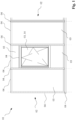
- Fig. 1 shows a front view of a wall system 01 in the assembled state.
- the wall system 01 consists of a first wall system part 02, to which a schematically illustrated second wall system part 02 is connected.
- the first wall system 01 comprises several frame parts 04 designed as posts and cross braces.
- the frame parts 04 each form rectangular frames into which surface components 03 are inserted.
- the surface components 03 are largely glazing with multiple insulating glass, whereby the frame parts 04 form a frame for forming a frame window together with the surface component 03.
- the centrally located surface component 03 is designed as a window sash 14.
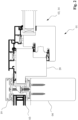
- Fig. 2 shows a sectional view of a wall system 01 from the prior art.
- This comprises a frame part 04, wherein a surface component 03 in the form of a multiple insulating glass pane is held on one side by means of a clamping element 19, and on the other side a frame 20 for forming a stop for a casement window 14 is held in place by a surface component 03.
- a surface component 03 in the form of a multiple insulating glass pane is held on one side by means of a clamping element 19, and on the other side a frame 20 for forming a stop for a casement window 14 is held in place by a surface component 03.
- the clamping element 19 it is necessary to attach the clamping element 19 on site to the frame part 04 to clamp the surface components 03 or the frame 20.
- manufacturing tolerances and/or assembly errors can only be compensated to a very limited extent.
- the thermal insulation, particularly along the clamping element 19, may have a weak point designed as a cold bridge.
- Fig. 3 shows sectional views of a first embodiment of a wall system 01 according to the invention.
- Fig. 3A shows a first embodiment of a frame part 04 with a main body 05.
- the main body 05 provides the frame part 04 with the necessary stability.
- a first connection area 06 with a cuboid cutout 07 is arranged on the main body 05.
- the depth corresponds to the depth of a surface component 03, which is received in the cuboid recess 07.
- the surface component 03 is flush with the frame part 04.
- a second connection area 06 is formed, which includes a projection 08 with steps.
- the projection 08 with steps forms a frame for a surface component 03 designed as a casement window 14.
- the surface component 03 which is accommodated in the cuboid-shaped cutout 07, is held by means of a holding element 17, with a dry glazing designed as a seal 16 being formed between the holding element 17 and the surface component 03.
- the holding element 17 is also attached to the frame part 04.
- a cover 18 is arranged on each of the holding element 17 and the frame part 04.
- Fig. 3B shows a cross section through two frame parts 04 of a second embodiment, which are connected to each other in a coupling area 09.
- the structure of the frame parts 04 essentially corresponds to that in Fig. 3A structure shown on the left, so that for the explanation of the individual elements, refer to the Fig. 3A
- the frame parts 04 In the coupling area 09, the frame parts 04 each have recesses that form a floating connection with a connecting element 10.
- a sealing strip 11 is also arranged between the frame parts 04.
- Fig. 3C shows a cross-section through a structure for forming a corner arranged in the wall system 01.
- two frame parts 04 of a third embodiment and one frame part 04 of a fourth embodiment are arranged to form a corner, wherein the two outer frame parts 04 are each of the third embodiment and have a connection area 06 with a cuboid cutout 07.
- the two frame parts 04 each have a coupling area 09, in which they form a floating support with one of the coupling areas 09 of the frame part 04 of the fourth embodiment located between them.
- the outer frame parts 04 of the third embodiment each have a cover element 18 and a holding element 17 holding the surface component 03.
- the frame part 04 of the fourth embodiment located between the two other frame parts 04 of the third embodiment has two cover elements 18.
- the cover elements 18 and the frame parts 04 are in the Fig. 3A to Fig. 3C shown version made of solid wood.
- Fig. 4 shows sectional views of a second embodiment of a wall system 01 according to the invention.
- the wall system 01 comprises a first frame part 04 made of solid wood, shown in Fig. 4A .
- the frame part 04 has a first connection area 06 with a cuboid-shaped cutout 07 in which a surface component 03 is received.
- the surface component 03 is held by a holding element 17, which is also designed as a cover element 18.
- the frame part 04 comprises a main body 05.
- a cutout 07 with steps is formed, which forms a frame for a surface component 03 designed as a window sash 14.
- the combined holding element 17 and cover element 18 is made of an aluminum profile.
- Fig. 4B shows a second frame part 04, designed as a lower closure, with a main body 05 and a connecting area 06 in which a guide rail 12 is arranged.
- the door leaf 15 of a sliding door is arranged on the connecting area 06 as a surface component 03.
Landscapes
- Engineering & Computer Science (AREA)
- Civil Engineering (AREA)
- Structural Engineering (AREA)
- Life Sciences & Earth Sciences (AREA)
- Wood Science & Technology (AREA)
- Architecture (AREA)
- Physics & Mathematics (AREA)
- Electromagnetism (AREA)
- Wing Frames And Configurations (AREA)
- Residential Or Office Buildings (AREA)
- Load-Bearing And Curtain Walls (AREA)
Applications Claiming Priority (1)
| Application Number | Priority Date | Filing Date | Title |
|---|---|---|---|
| DE202023105916.3U DE202023105916U1 (de) | 2023-10-13 | 2023-10-13 | Rahmenteil für ein Wandsystem und Wandsystem |
Publications (2)
| Publication Number | Publication Date |
|---|---|
| EP4538492A2 true EP4538492A2 (fr) | 2025-04-16 |
| EP4538492A3 EP4538492A3 (fr) | 2025-05-28 |
Family
ID=89808637
Family Applications (1)
| Application Number | Title | Priority Date | Filing Date |
|---|---|---|---|
| EP24203914.7A Pending EP4538492A3 (fr) | 2023-10-13 | 2024-10-01 | Élément de cadre pour un système de mur et système de mur |
Country Status (2)
| Country | Link |
|---|---|
| EP (1) | EP4538492A3 (fr) |
| DE (1) | DE202023105916U1 (fr) |
Family Cites Families (3)
| Publication number | Priority date | Publication date | Assignee | Title |
|---|---|---|---|---|
| EP1561892B1 (fr) * | 2004-02-06 | 2012-10-24 | Eichinger Schreinerei GmbH | Système de revêtement pour surfaces extérieures ou intérieures de bâtiments, portes, fenêtres et similaires |
| EP2246496B1 (fr) * | 2009-04-21 | 2013-10-02 | 4B Holding AG | Système de fixation d'un élément d'insertion dans un élément de façade et procédé de montage du système de fixation |
| CN113089908B (zh) * | 2021-05-10 | 2022-08-16 | 中建一局华江建设有限公司 | 一种木质龙骨玻璃幕墙系统及其施工方法 |
-
2023
- 2023-10-13 DE DE202023105916.3U patent/DE202023105916U1/de active Active
-
2024
- 2024-10-01 EP EP24203914.7A patent/EP4538492A3/fr active Pending
Also Published As
| Publication number | Publication date |
|---|---|
| EP4538492A3 (fr) | 2025-05-28 |
| DE202023105916U1 (de) | 2024-01-15 |
Similar Documents
| Publication | Publication Date | Title |
|---|---|---|
| DE1509553A1 (de) | Fensterkonstruktion | |
| EP3954854A1 (fr) | Ensemble de vitrage isolant adaptatif (variantes) | |
| EP4538492A2 (fr) | Élément de cadre pour un système de mur et système de mur | |
| EP0730068B1 (fr) | Lucarne | |
| DE4124820C1 (en) | Metal or glass facade or roof - has main glazing bars with sealing strips cut-out to accommodate cross-bars | |
| DE2437296A1 (de) | Hohlprofilleiste | |
| EP0725203B1 (fr) | Armature pour portes, fenêtres ou façades | |
| EP0902154B1 (fr) | Vitrage pare-feu | |
| EP3543450A1 (fr) | Système de profilé de porte relevable et coulissante / coulissante | |
| EP1524378B1 (fr) | Façade de montants et de traverses avec fenêtres | |
| DE2557878C3 (de) | Schallschutzfenster | |
| DE102017118275B4 (de) | Torvorrichtung und diese enthaltende Toranordnung | |
| EP3862523A1 (fr) | Profilé | |
| DE1459901C3 (de) | Gebäude, das eine Front mit Loggien aufweist | |
| DE19709938A1 (de) | Fensteranordnung | |
| DE19616490A1 (de) | Fassadenpaneel und System zum Befestigen von flächigen Fassadenelementen | |
| EP4001531B1 (fr) | Ensemble pour une cabane à outils | |
| EP4102021B1 (fr) | Profilé de chambre creuse de fenêtre ou de porte, système doté d'un tel profilé de chambre creuse et châssis fabriqué à partir de celui-ci | |
| DE102008040296B4 (de) | Pfosten für eine Pfosten-Riegel- oder Elementkonstruktion, Verfahren zu dessen Herstellung und Pfosten-Riegel- oder Elementkonstruktion, die einen Pfosten aufweist | |
| DE3347583A1 (de) | Feuerbestaendige fensterwand | |
| DE1509571B1 (de) | Fenster- oder Fenstertuerfertigbauteil,das als Ganzes in Wandoeffnungen von Gebaeuden einsetzbar ist | |
| DE3049605A1 (de) | Rahmen-fluegel-aufbau fuer fenster, tueren o.dgl. | |
| DE19616145A1 (de) | Fensterinnenverkleidung | |
| DE4011167A1 (de) | Feuerhemmende trennwand | |
| DE102023130368A1 (de) | Strukturgebäude zum Eigenbau |
Legal Events
| Date | Code | Title | Description |
|---|---|---|---|
| PUAI | Public reference made under article 153(3) epc to a published international application that has entered the european phase |
Free format text: ORIGINAL CODE: 0009012 |
|
| STAA | Information on the status of an ep patent application or granted ep patent |
Free format text: STATUS: THE APPLICATION HAS BEEN PUBLISHED |
|
| AK | Designated contracting states |
Kind code of ref document: A2 Designated state(s): AL AT BE BG CH CY CZ DE DK EE ES FI FR GB GR HR HU IE IS IT LI LT LU LV MC ME MK MT NL NO PL PT RO RS SE SI SK SM TR |
|
| PUAL | Search report despatched |
Free format text: ORIGINAL CODE: 0009013 |
|
| AK | Designated contracting states |
Kind code of ref document: A3 Designated state(s): AL AT BE BG CH CY CZ DE DK EE ES FI FR GB GR HR HU IE IS IT LI LT LU LV MC ME MK MT NL NO PL PT RO RS SE SI SK SM TR |
|
| RIC1 | Information provided on ipc code assigned before grant |
Ipc: E04B 2/96 20060101ALI20250422BHEP Ipc: E06B 3/54 20060101ALI20250422BHEP Ipc: E06B 3/10 20060101ALI20250422BHEP Ipc: E06B 1/06 20060101AFI20250422BHEP |
|
| STAA | Information on the status of an ep patent application or granted ep patent |
Free format text: STATUS: REQUEST FOR EXAMINATION WAS MADE |
|
| 17P | Request for examination filed |
Effective date: 20250717 |