EP4538600A1 - Four avec module de cuisson partiellement extractible sur rails fixes - Google Patents
Four avec module de cuisson partiellement extractible sur rails fixes Download PDFInfo
- Publication number
- EP4538600A1 EP4538600A1 EP24020308.3A EP24020308A EP4538600A1 EP 4538600 A1 EP4538600 A1 EP 4538600A1 EP 24020308 A EP24020308 A EP 24020308A EP 4538600 A1 EP4538600 A1 EP 4538600A1
- Authority
- EP
- European Patent Office
- Prior art keywords
- oven
- cooking
- module
- fact
- side wall
- Prior art date
- Legal status (The legal status is an assumption and is not a legal conclusion. Google has not performed a legal analysis and makes no representation as to the accuracy of the status listed.)
- Pending
Links
Images




Classifications
-
- F—MECHANICAL ENGINEERING; LIGHTING; HEATING; WEAPONS; BLASTING
- F24—HEATING; RANGES; VENTILATING
- F24C—DOMESTIC STOVES OR RANGES ; DETAILS OF DOMESTIC STOVES OR RANGES, OF GENERAL APPLICATION
- F24C15/00—Details
- F24C15/08—Foundations or supports plates; Legs or pillars; Casings; Wheels
Definitions
- the subject of this invention is an oven with partially extractable cooking module on fixed tracks.
- This invention intends to propose a new and beneficial solution of an oven that significantly facilitates the maintenance and inspection of these and other functional parts, which are grouped closer together, exposed, and easily accessible with respect to conventional and known solutions.
- the proposed cooking oven is especially suitable for community catering, where practicality and ease of use are essential, and it is also essential to carry out frequent routine maintenance in situ, reducing inconvenience in the kitchen and limiting repair times, resulting in lower global costs.
- a metal structural frame is equipped with a first and a second telescopic guide fastened to the sides, in such a way that the first guide is specular and symmetrical with respect to the second guide, and wherein said oven rotary support shelf is fastened in correspondence with the retractable segments at the end opposite to the fastened segments.
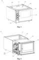
- a cooking oven (10, 10a) for community catering composed of a fixed part comprising an outer body (100) functioning as an enclosure and support, and a mobile part comprising a cooking module (101) mounted inside the body and at least partially extractable (EP) by traversing horizontally on fixed tracks (114) and corresponding carriages (115, 116) mounted under the module.
- the cooking module (101) has at least said functional parts (110) which are mounted on a side of the oven chamber (102) to form an equipped side wall (108), accommodated in an open space bounded by the body in the form of a housing (109), and easily accessible at the side with the module partially extracted (EP) for routine maintenance tasks.
- the opposite side is blank (107) and adjacent to the body; consequently, the oven (10, 10a) has a narrower oven chamber (101) that is off-centre with respect to the body (100), having the equipped side wall (108, 109) located to the side, with the functional equipment (110, 110a - 110q) exposed.
- a second variant of the electric convection oven is envisaged with mechanical thermostat control, and including at least one lateral heating element with multi-speed ventilation means, a manual humidifier, manual air inlet valve management means, control means with mechanical relays and contactors.
- a fourth variant of the combined oven is envisaged with multifunction electronic swipe or touch automatic control means, including at least one lateral heating element with multi-speed ventilation means, an upper static heating element with independent manual control, a possible lower static heating element with independent manual control, integrated automatic washing means, a humidification system with humidity percentage management, means for dry, steam, or combined cooking, multiple preloaded cooking programs with personalised management of recipes, control means with electronic power relays of the solid state or SSR type, fan speed control means with an inverter, having for example six speed levels.
- the oven (10) has an oven chamber (102) of standardised capacity, in compliance with European Gastronorm regulations, for example 4 GN 2/1 containers or 8 GN 1/1 containers, or also 4 GN1/1 containers.
- the oven (10) can be installed under a standardised professional kitchen element, for example having a body (100) 800 mm wide and from 700 mm to 900 mm deep.
- the oven can therefore be beneficially integrated in commonly used community catering kitchen equipment.
- the oven (10) is schematically represented with the module (101) partially extracted, to allow routine maintenance tasks, having the functional equipment mounted on an equipped side wall (108) of the oven chamber (102), all on the same side and easily accessible.
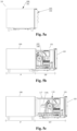
- the first figure ( Fig. 8a ) shows the oven individually integrated between kitchen units and appliances of identical height and width, with the body functioning as a support base for a professional hob, a griddle or a grill (118).
- the oven is shown in a multiple configuration, joined to and aligned with identical ovens, being respectively positioned side by side in a horizontal in-line array ( Fig. 8b ) or stacked in a vertical wall-standing or column mounted array ( Fig. 8c ).
- blank side wall of the body (129) refers to a side wall of the body (100) that is closed and without functional parts; by extension, a configuration of a blank side wall wherein, in place of or in combination with said closed side of the body there is an adjacent kitchen unit, or an adjacent wall, with an identical closing effect is construed as included and equivalent in the context of this description.
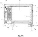
- the proposed solution principally solves the aforementioned problem of overheating of the body in correspondence with the blank side wall (107) of the module (102, 103) adjoining said blank side wall (129) of the body (100) construed as described above, without incorporating any dedicated device inside it and without obstructing extraction of the module, thus solving the mentioned safety problems in the oven and/or by extension in the adjacent kitchen units and/or in walls adjacent to its side ( Figs. 10 , 11, 12 ).
Landscapes
- Engineering & Computer Science (AREA)
- Chemical & Material Sciences (AREA)
- Combustion & Propulsion (AREA)
- Mechanical Engineering (AREA)
- General Engineering & Computer Science (AREA)
- Electric Stoves And Ranges (AREA)
Applications Claiming Priority (2)
| Application Number | Priority Date | Filing Date | Title |
|---|---|---|---|
| IT202023000004203U IT202300004203U1 (it) | 2023-10-12 | 2023-10-12 | Forno con modulo di cottura parzialmente estraibile su binari fissi |
| IT202400004077 | 2024-10-09 |
Publications (1)
| Publication Number | Publication Date |
|---|---|
| EP4538600A1 true EP4538600A1 (fr) | 2025-04-16 |
Family
ID=93335306
Family Applications (1)
| Application Number | Title | Priority Date | Filing Date |
|---|---|---|---|
| EP24020308.3A Pending EP4538600A1 (fr) | 2023-10-12 | 2024-10-10 | Four avec module de cuisson partiellement extractible sur rails fixes |
Country Status (1)
| Country | Link |
|---|---|
| EP (1) | EP4538600A1 (fr) |
Citations (5)
| Publication number | Priority date | Publication date | Assignee | Title |
|---|---|---|---|---|
| DE1247592B (de) * | 1959-03-23 | 1967-08-17 | Siemens Electrogeraete Ges Mit | Einbauherd |
| JPS5634205U (fr) * | 1979-08-23 | 1981-04-03 | ||
| JPS6016240A (ja) * | 1984-06-07 | 1985-01-28 | Matsushita Electric Ind Co Ltd | 加熱調理器 |
| US7287462B2 (en) | 2000-12-01 | 2007-10-30 | Bsh Bosch Und Siemens Hausgeraete Gmbh | High-level built-in oven unit |
| WO2010125010A1 (fr) | 2009-04-28 | 2010-11-04 | Meneghetti - S.P.A. Unipersonale - | Four encastré verticalement mobile |
-
2024
- 2024-10-10 EP EP24020308.3A patent/EP4538600A1/fr active Pending
Patent Citations (5)
| Publication number | Priority date | Publication date | Assignee | Title |
|---|---|---|---|---|
| DE1247592B (de) * | 1959-03-23 | 1967-08-17 | Siemens Electrogeraete Ges Mit | Einbauherd |
| JPS5634205U (fr) * | 1979-08-23 | 1981-04-03 | ||
| JPS6016240A (ja) * | 1984-06-07 | 1985-01-28 | Matsushita Electric Ind Co Ltd | 加熱調理器 |
| US7287462B2 (en) | 2000-12-01 | 2007-10-30 | Bsh Bosch Und Siemens Hausgeraete Gmbh | High-level built-in oven unit |
| WO2010125010A1 (fr) | 2009-04-28 | 2010-11-04 | Meneghetti - S.P.A. Unipersonale - | Four encastré verticalement mobile |
Similar Documents
| Publication | Publication Date | Title |
|---|---|---|
| CA2365023C (fr) | Systeme pour faire griller des aliments dans une cavite de four avec elimination de sous-produits | |
| US9513016B2 (en) | Bottom-loading cooking appliance | |
| CN109416186B (zh) | 用于下吸式抽油烟机的插入件 | |
| KR102824831B1 (ko) | 호브 시스템 | |
| KR101520499B1 (ko) | 오븐 레인지 | |
| KR20140030020A (ko) | 무연 그릴 | |
| JP5702815B2 (ja) | 加熱調理器 | |
| JPWO2017145792A1 (ja) | 誘導加熱調理器 | |
| EP4538600A1 (fr) | Four avec module de cuisson partiellement extractible sur rails fixes | |
| EP4528111A2 (fr) | Plaque de cuisson avec hotte aspirante | |
| KR100866501B1 (ko) | 내부 조리공간을 갖는 후드의 배기구조 | |
| RU93502U1 (ru) | Плита электрическая с жарочным шкафом (варианты) | |
| KR20210008811A (ko) | 밀폐형 무연 자동 튀김장치 | |
| CN222278669U (zh) | 一种多用途集成灶 | |
| US20180283699A1 (en) | Oven range appliance having a ventilation system | |
| US11988392B2 (en) | Removable heating element cover for an oven appliance and methods of detecting same | |
| JP2016169940A (ja) | 加熱調理器 | |
| KR200312289Y1 (ko) | 테이블 부착형 튀김기 | |
| KR102424073B1 (ko) | 족발용 인덕션 조리기 | |
| IT202300004203U1 (it) | Forno con modulo di cottura parzialmente estraibile su binari fissi | |
| KR101801326B1 (ko) | 인덕션 오븐레인지의 환기시스템 | |
| GB2349457A (en) | Cooking appliance | |
| EP4595840A1 (fr) | Friteuse à air avec aspiration d'air sur une partie latérale | |
| JP6270886B2 (ja) | 加熱調理器 | |
| EP4365494A1 (fr) | Hotte aspirante de cuisine et système de cuisson |
Legal Events
| Date | Code | Title | Description |
|---|---|---|---|
| PUAI | Public reference made under article 153(3) epc to a published international application that has entered the european phase |
Free format text: ORIGINAL CODE: 0009012 |
|
| STAA | Information on the status of an ep patent application or granted ep patent |
Free format text: STATUS: THE APPLICATION HAS BEEN PUBLISHED |
|
| AK | Designated contracting states |
Kind code of ref document: A1 Designated state(s): AL AT BE BG CH CY CZ DE DK EE ES FI FR GB GR HR HU IE IS IT LI LT LU LV MC ME MK MT NL NO PL PT RO RS SE SI SK SM TR |
|
| RIN1 | Information on inventor provided before grant (corrected) |
Inventor name: MINELLA, ANDREA Inventor name: TEGNER, MARCO Inventor name: BRISTOT, DANIELE Inventor name: ZOCCOLAN, ADAMO Inventor name: D'AMBROGIO, MARCO |
|
| P01 | Opt-out of the competence of the unified patent court (upc) registered |
Free format text: CASE NUMBER: APP_29275/2025 Effective date: 20250619 |
|
| STAA | Information on the status of an ep patent application or granted ep patent |
Free format text: STATUS: REQUEST FOR EXAMINATION WAS MADE |
|
| 17P | Request for examination filed |
Effective date: 20250729 |
|
| RIN1 | Information on inventor provided before grant (corrected) |
Inventor name: D'AMBROGIO, MARCO Inventor name: ZOCCOLAN, ADAMO Inventor name: BRISTOT, DANIELE Inventor name: TEGNER, MARCO Inventor name: MINELLA, ANDREA |