EP4538748A1 - Réglage de seuils de détection de signal - Google Patents
Réglage de seuils de détection de signal Download PDFInfo
- Publication number
- EP4538748A1 EP4538748A1 EP23203316.7A EP23203316A EP4538748A1 EP 4538748 A1 EP4538748 A1 EP 4538748A1 EP 23203316 A EP23203316 A EP 23203316A EP 4538748 A1 EP4538748 A1 EP 4538748A1
- Authority
- EP
- European Patent Office
- Prior art keywords
- signal
- noise
- bins
- code
- determining
- Prior art date
- Legal status (The legal status is an assumption and is not a legal conclusion. Google has not performed a legal analysis and makes no representation as to the accuracy of the status listed.)
- Pending
Links
Images


Classifications
-
- G—PHYSICS
- G01—MEASURING; TESTING
- G01S—RADIO DIRECTION-FINDING; RADIO NAVIGATION; DETERMINING DISTANCE OR VELOCITY BY USE OF RADIO WAVES; LOCATING OR PRESENCE-DETECTING BY USE OF THE REFLECTION OR RERADIATION OF RADIO WAVES; ANALOGOUS ARRANGEMENTS USING OTHER WAVES
- G01S19/00—Satellite radio beacon positioning systems; Determining position, velocity or attitude using signals transmitted by such systems
- G01S19/01—Satellite radio beacon positioning systems transmitting time-stamped messages, e.g. GPS [Global Positioning System], GLONASS [Global Orbiting Navigation Satellite System] or GALILEO
- G01S19/13—Receivers
- G01S19/24—Acquisition or tracking or demodulation of signals transmitted by the system
- G01S19/30—Acquisition or tracking or demodulation of signals transmitted by the system code related
-
- G—PHYSICS
- G01—MEASURING; TESTING
- G01S—RADIO DIRECTION-FINDING; RADIO NAVIGATION; DETERMINING DISTANCE OR VELOCITY BY USE OF RADIO WAVES; LOCATING OR PRESENCE-DETECTING BY USE OF THE REFLECTION OR RERADIATION OF RADIO WAVES; ANALOGOUS ARRANGEMENTS USING OTHER WAVES
- G01S19/00—Satellite radio beacon positioning systems; Determining position, velocity or attitude using signals transmitted by such systems
- G01S19/01—Satellite radio beacon positioning systems transmitting time-stamped messages, e.g. GPS [Global Positioning System], GLONASS [Global Orbiting Navigation Satellite System] or GALILEO
- G01S19/13—Receivers
- G01S19/21—Interference related issues ; Issues related to cross-correlation, spoofing or other methods of denial of service
-
- G—PHYSICS
- G01—MEASURING; TESTING
- G01S—RADIO DIRECTION-FINDING; RADIO NAVIGATION; DETERMINING DISTANCE OR VELOCITY BY USE OF RADIO WAVES; LOCATING OR PRESENCE-DETECTING BY USE OF THE REFLECTION OR RERADIATION OF RADIO WAVES; ANALOGOUS ARRANGEMENTS USING OTHER WAVES
- G01S19/00—Satellite radio beacon positioning systems; Determining position, velocity or attitude using signals transmitted by such systems
- G01S19/01—Satellite radio beacon positioning systems transmitting time-stamped messages, e.g. GPS [Global Positioning System], GLONASS [Global Orbiting Navigation Satellite System] or GALILEO
- G01S19/13—Receivers
- G01S19/23—Testing, monitoring, correcting or calibrating of receiver elements
- G01S19/235—Calibration of receiver components
Definitions
- the present invention relates to Navigation Satellite Systems (NSS). These include Global Navigation Satellite Systems (GNSS) and also regional Navigation Satellite Systems. In particular, it relates to a method for setting detection threshold in a signal acquisition process.
- NSS Navigation Satellite Systems
- GNSS Global Navigation Satellite Systems
- GNSS Global Navigation Satellite Systems
- GNSS regional Navigation Satellite Systems
- the frequency received by an antenna may vary from the emitted frequency due to Doppler shift and/or unknown receiver clock drift.
- a range of Doppler frequencies must therefore be searched in order to identify a signal.
- a known code specific to the satellite is used in order to identify a signal.
- the time delay of the code is not known and therefore a range of code delays must be tried, or compared, to identify the signal.
- a range of frequencies over a range of code delays must be searched in order to identify, or acquire, the signal. This generates a 2D search space of correlation values calculated for different combinations of Doppler frequency shift and code delay.
- a high correlation value for a specific Doppler frequency and code delay combination may indicate a signal.
- the signal threshold for optimal detection varies with the integration time. Additionally, the threshold varies depending on the size of the search space.
- a commonly used approach is to maintain look-up tables for the signal thresholds for different sizes of search space and different integration times. However, this requires a huge set of look-up tables to be stored which is very inefficient and occupies large amounts of memory.
- a signal detection threshold By calculating a signal detection threshold the need for very large look-up tables is obviated.
- a signal detection threshold based on the specific search space, and the associated expected noise level(s) are calculated. As the expected maximum noise level is calculated specifically for the search space used false positives are minimised and signals are detected more consistently.
- the signal detection threshold By setting the signal detection threshold based on an expected maximum noise value for a search space of the relevant size there is a consistent false positive rate regardless of the size of the search space. If the search space is changed the signal detection threshold can be recalculated to maintain a consistent false positive rate.
- the signal level in each bin is compared to the signal detection threshold and, once a signal level above the signal detection threshold is detected it may no longer be necessary to compare the signal level in further bins to the signal detection threshold because the signal has already been identified. This, in turn, saves computational resources in the system.
- the frequency of the identified signal may be determined and also the code delay of the identified signal determined.
- the identified signal can then be tracked using known tracking mechanisms.
- the pseudo-range of the satellite from which the signal is emitted may be determined.
- a position fix may also be determined. This may be generalised as a position, velocity, time "PVT" fix.
- Determining noise may optionally comprise correlating the signal in a bin with a predetermined code.
- the code may be a random code, or may be, for example, all ones or all zeros.
- Determining noise in a plurality of search bins may comprise determining noise in all the search bins.
- the method may further comprise setting a second signal detection threshold over a second range of frequencies, different from the first range of frequencies and a second range of code delays, different from the first range of code delays, the method further comprising setting a second number of frequency bins, setting a second number of code delay bins, determining the noise in a plurality of the search bins, determining an integration time t, determining the number of search bins n, calculating the expected mean noise and standard deviation of the maximum of all noise bins based on the number of search bins and the standard deviation of the noise in the plurality of search bins, calculating the signal detection threshold based on a number of standard deviations from the maximum noise signal and setting a second signal detection threshold.
- the second signal detection threshold may be different from the initial signal detection threshold.
- the second signal detection threshold may be set as the same number of standard deviations from the maximum expected noise signal as the initial signal detection threshold was set. Advantageously, this would maintain a constant error rate.
- the signal level in each bin may be detected and one or more signals above the signal detection threshold identified.
- the frequency and code delay of the identified signal may be determined.
- a computer program comprising computer program code configured to cause one or more physical computing devices to perform all the steps of the method as claimed in any one of the preceding claims when said computer program is run on said one or more physical computing devices.
- GNSS Global Navigation Satellite System
- the GNSS receiver comprising a processor configured to carry out the steps as described above.
- an acquisition threshold is calculated based on, for example, the number of search bins, the integration time and the measured noise value. This obviates the need for large data tables to be stored and accessed each time an acquisition threshold is to be set.
- the GNSS satellites of these various systems typically transmit GNSS signals in more than one frequency band.
- the frequency bands which are currently available under GPS include the L1, L2 and L5 bands.
- the signal carrier frequency is generally in the range of 1.559 GHz to 1.610 GHz.
- the signal carrier frequency is generally in the range of 1.18845 GHz to 1.258 GHz.
- the signal carrier frequency is generally in the range of 1.164 GHz to 1.189 GHz. Additional or different frequency bands may become available in the future for GPS.
- L1, L2 and L5 within GPS have different chipping rates: L1 has a chipping rate of 1.023MHz, L2 has a chipping rate of 511.5kHz whereas L5 has a faster chipping rate of 10.23MHz. As L5 has a faster chipping rate the peak of the correlation functions become narrower than those of L1 and L2. For example, a correlation peak of L1 corresponds to 293m whereas a correlation peak of L5 corresponds to 29.3m. Due to the narrower correlation functions, it is easier to distinguish between L5 signals transmitted by different paths (for example due to reflections in a multipath environment) than it is to distinguish between L1 or L2 signals transmitted by different paths. Thus, L5 signals are more resistant in multipath environments than L1 signals. As further examples of chipping rates GLO has a chipping rate of 511kHz on L1 and BDS has 2.046MHz for L1.
- a GNSS receiver may operate in a single-band mode in which it performs signal processing to determine navigation measurements on signals in only one band, for example, the L1 band only or, as another example, the L5 band only.
- the GNSS receiver may operate in a dual- or multi-band mode in which it performs signal processing using signals in multiple bands within a particular constellation, for example, L1 and L5 dual-band mode in GPS.
- a GNSS receiver may be configured to operate in a multi-band mode in which three or more signal bands are utilized (e.g., L1, L2 and L5). It is generally expected that multi-band processing will achieve more accurate navigation measurements than single-band processing.
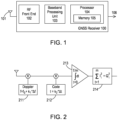
- FIG. 1 illustrates a block schematic diagram of a GNSS receiver 100 for determining verification of a PVT solution in a global navigation satellite system in accordance with an embodiment of the present invention.
- the GNSS receiver 100 is configured to receive GNSS satellite signals from GNSS satellites via an antenna 101.
- the received signals are passed from the antenna 101 to RF front-end 102 which performs tasks such as amplification, down-conversion, filtering and digitization of the captured satellite signals.
- the RF front-end 102 may include further functionality such as frequency synthesis (not shown).
- the receiver 100 is further configured to process the received signals using a processor 104 to extract observables and navigation data from each channel of the baseband processing unit 103 and to generate a navigation solution 106.
- the processor 104 may include an internal or external memory 105 for storing and/or retrieving data associated with the processing.
- the system described above is used to determine a navigation solution.
- the transmission frequency of satellites is known, Doppler shift and also atmospheric effects mean that the frequency at the receiver may be different. The frequency could be higher or lower and the receiver will therefore need to search a range of frequencies in order to find the frequency at the receiver.
- each bin having a defined frequency and defined code delay
- Most of the bins will simply have noise but some bins may have a higher output value than the other bins, which could indicate a signal at the frequency and code delay of the respective bin.
- a threshold must be set for the identification of a signal. If the threshold is set too low then there will be too many false positives. On the other hand, if the signal is set too high then the signal will not be identified. It is therefore desirable to deduce the maximum noise level for a set of bins.
- the complex signal values are normally distributed according to I m , Q m ⁇ N(0, m ⁇ 2 ) where m is the coherent integration time in ms.
- the distribution the values are distributed as ⁇ N(0, cm ⁇ 2 ) for a code length c or ⁇ N(0, 1023 m ⁇ 2 ) for a code of length 1023.
- the magnitude of this follows a Rayleigh distribution -Rayleigh ( c m ⁇ ) with a mean of c m ⁇ ⁇ / 2 .
- a Rayleigh distribution is formed.
- L1CA c is 1023 but for other code lengths it would be a different length.
- the integration time t is determined.
- the number of bins n is determined.
- the standard deviation ⁇ of a single noise bin is then determined at step 304.
- the bins can be processed using the system depicted in Figure 2 , namely multiplying by a replica carrier frequency at different frequencies and a replica pseudorandom code at different code delays.
- the signals in individual bins can then be compared to the detection threshold. Once a signal above the signal detection threshold is found then a signal is identified. If a signal is identified it is not necessary to consider any remaining search bins because, for each pseudorandom code there is only one signal. If the signal has been found then the remaining bins will not include the signal.
- the code delay and the frequency of the signal are determined as the code delay and frequency of the respective bin from which the signal was identified.
- Figure 5 depicts a further method according to the invention.
- the method of Figure 5 continues from the method of Figure 3 .
- a signal above the signal threshold is identified at step 500.
- This signal has a frequency and a code delay.
- a second search area is then identified by setting 500a a second number of frequency bins and setting 500b a second number of code delay bins.
- the second search area may be much smaller and centred on the originally identified frequency and code delay. Indeed the entire search area may be within the originally identified search bin.
- the frequency range ⁇ f and code delay range ⁇ t of each search bin may be considerably smaller. Consequently, the result would give a greater accuracy of frequency and code delay.
- the noise is determined at step 501.
- the integration time is then determined at step 502 and the number of bins n is determined at step 503. Although the average noise per bin is consistent with the earlier method there may be a different number of bins and therefore the expected maximum noise level may change.
- the standard deviation of a single noise bin in the plurality of noise bins is determined.
- a signal can then be acquired in a smaller search area to obtain a more accurate estimate of the frequency and code delay.
- Figure 5 is described in conjunction with a smaller search area it could equally be used in conjunction with a larger search area. However, for each search area there will be a constant error, or false positive, rate because the signal detection threshold is set as the same number of standard deviations from the expected noise level of the maximum noise bin.
- a method for obtaining the noise level per bin is depicted in Fig 4 .
- a signal is detected.
- the signal is then correlated with a series of ones. Although the example given here is a series of ones any random (but not a designated pseudorandom) code could be used.
- the magnitude of the correlated signal is then obtained at step 403.
- any reference signs placed between parentheses shall not be construed as limiting the claim.
- the word “comprising” does not exclude the presence of elements or steps other than those listed in a claim. However, where the word “comprising” is used, this also discloses as a special case the possibility that the elements or steps listed are exhaustive - that is, the apparatus or method may consist solely of those elements or steps.
- the word “a” or “an” preceding an element does not exclude the presence of a plurality of such elements.
- the embodiments may be implemented by means of hardware comprising several distinct elements. In a device claim enumerating several means, several of these means may be embodied by one and the same item of hardware.
- the various embodiments may be implemented in hardware or special purpose circuits, software, logic or any combination thereof.
- some aspects may be implemented in hardware, while other aspects may be implemented in firmware or software, which may be executed by a controller, microprocessor or other computing device, although these are not limiting examples.
- firmware or software which may be executed by a controller, microprocessor or other computing device, although these are not limiting examples.
- various aspects described herein may be illustrated and described as block diagrams, flow charts, or using some other pictorial representation, it is well understood that these blocks, apparatus, systems, techniques or methods described herein may be implemented in, as non-limiting examples, hardware, software, firmware, special purpose circuits or logic, general purpose hardware or controller or other computing devices, or some combination thereof.
- any blocks of the logic flow as in the Figures may represent program steps, or interconnected logic circuits, blocks and functions, or a combination of program steps and logic circuits, blocks and functions.
- the software may be stored on such physical media as memory chips, or memory blocks implemented within the processor, magnetic media such as hard disk or floppy disks, and optical media such as for example DVD and the data variants thereof, CD.
- Embodiments as discussed herein may be practiced in various components such as integrated circuit modules.
- the design of integrated circuits is generally a highly automated process. Complex and powerful software tools are available for converting a logic level design into a semiconductor circuit design ready to be etched and formed on a semiconductor substrate.
Landscapes
- Engineering & Computer Science (AREA)
- Radar, Positioning & Navigation (AREA)
- Remote Sensing (AREA)
- Computer Networks & Wireless Communication (AREA)
- Physics & Mathematics (AREA)
- General Physics & Mathematics (AREA)
- Position Fixing By Use Of Radio Waves (AREA)
Priority Applications (3)
| Application Number | Priority Date | Filing Date | Title |
|---|---|---|---|
| EP23203316.7A EP4538748A1 (fr) | 2023-10-12 | 2023-10-12 | Réglage de seuils de détection de signal |
| US18/909,157 US20250123405A1 (en) | 2023-10-12 | 2024-10-08 | Setting signal detection thresholds |
| CN202411416528.7A CN119828182A (zh) | 2023-10-12 | 2024-10-11 | 设置信号检测阈值 |
Applications Claiming Priority (1)
| Application Number | Priority Date | Filing Date | Title |
|---|---|---|---|
| EP23203316.7A EP4538748A1 (fr) | 2023-10-12 | 2023-10-12 | Réglage de seuils de détection de signal |
Publications (1)
| Publication Number | Publication Date |
|---|---|
| EP4538748A1 true EP4538748A1 (fr) | 2025-04-16 |
Family
ID=88412288
Family Applications (1)
| Application Number | Title | Priority Date | Filing Date |
|---|---|---|---|
| EP23203316.7A Pending EP4538748A1 (fr) | 2023-10-12 | 2023-10-12 | Réglage de seuils de détection de signal |
Country Status (3)
| Country | Link |
|---|---|
| US (1) | US20250123405A1 (fr) |
| EP (1) | EP4538748A1 (fr) |
| CN (1) | CN119828182A (fr) |
Citations (4)
| Publication number | Priority date | Publication date | Assignee | Title |
|---|---|---|---|---|
| WO2000033471A1 (fr) * | 1998-11-28 | 2000-06-08 | Koninklijke Philips Electronics N.V. | Recepteur de signaux ds-cdma dans les systemes de navigation par satellite |
| CN1592471A (zh) * | 2003-09-04 | 2005-03-09 | 华为技术有限公司 | 一种抑制到达时间附加时延误差的方法 |
| US20070268960A1 (en) * | 2006-05-17 | 2007-11-22 | Zhike Jia | Systems and methods for signal acquistion in navigational satellite signal receivers |
| WO2013140910A1 (fr) * | 2012-03-22 | 2013-09-26 | 古野電気株式会社 | Procédé, programme et dispositif de recherche de signal, récepteur de signal gnss (système de navigation global par satellite), et terminal d'information |
-
2023
- 2023-10-12 EP EP23203316.7A patent/EP4538748A1/fr active Pending
-
2024
- 2024-10-08 US US18/909,157 patent/US20250123405A1/en active Pending
- 2024-10-11 CN CN202411416528.7A patent/CN119828182A/zh active Pending
Patent Citations (4)
| Publication number | Priority date | Publication date | Assignee | Title |
|---|---|---|---|---|
| WO2000033471A1 (fr) * | 1998-11-28 | 2000-06-08 | Koninklijke Philips Electronics N.V. | Recepteur de signaux ds-cdma dans les systemes de navigation par satellite |
| CN1592471A (zh) * | 2003-09-04 | 2005-03-09 | 华为技术有限公司 | 一种抑制到达时间附加时延误差的方法 |
| US20070268960A1 (en) * | 2006-05-17 | 2007-11-22 | Zhike Jia | Systems and methods for signal acquistion in navigational satellite signal receivers |
| WO2013140910A1 (fr) * | 2012-03-22 | 2013-09-26 | 古野電気株式会社 | Procédé, programme et dispositif de recherche de signal, récepteur de signal gnss (système de navigation global par satellite), et terminal d'information |
Also Published As
| Publication number | Publication date |
|---|---|
| US20250123405A1 (en) | 2025-04-17 |
| CN119828182A (zh) | 2025-04-15 |
Similar Documents
| Publication | Publication Date | Title |
|---|---|---|
| US6236354B1 (en) | Reducing satellite signal interference in a global positioning system receiver | |
| US8106822B2 (en) | System and method for GNSS position aided signal acquisition | |
| US7965230B2 (en) | Satellite time determination for SPS receiver | |
| US7944394B2 (en) | Method and apparatus for validating a position in a satellite positioning system using range-rate measurements | |
| EP2348335A1 (fr) | Récepteur et procédé pour l'authentification de signaux satellites | |
| EP4158385A1 (fr) | Suivi de signaux et acquisition de codes secondaires gnss de qualité grand public modernisés | |
| US20120293369A1 (en) | System, method and computer program for navigation data bit synchronization for a gnss receiver | |
| US8970431B2 (en) | Method and apparatus for weak data bit sync in a positioning system | |
| CN102016621A (zh) | 用于互相关毛刺减轻的装置和方法 | |
| US11391847B2 (en) | GNSS correlation distortion detection and mitigation | |
| US7612713B2 (en) | First output position calculation method, storage medium, positioning device, and electronic instrument | |
| US7479924B2 (en) | False reacquisition mitigation in high sensitivity navigational satellite signal receivers | |
| EP2243035B1 (fr) | Mesure du potentiel d'énergie (rapport signal-bruit) dans des récepteurs numériques de systèmes mondiaux de satellites de navigation | |
| EP4538748A1 (fr) | Réglage de seuils de détection de signal | |
| US20250052912A1 (en) | Gnss measurement processing to identify modes | |
| JPH07280912A (ja) | Gps受信機 | |
| KR100687243B1 (ko) | 다중 경로 오차 제거를 위한 코드추적루프 및 다중 경로오차 제거 방법 | |
| US8233516B2 (en) | Wideband correlation mode switching methods and apparatuses | |
| EP4215947B1 (fr) | Détection de verrouillage de signal gnss | |
| US20240393472A1 (en) | System and method for time-of-flight determination using categorization of both code and phase in received signal | |
| US20250052911A1 (en) | Integration for gnss measurement processing | |
| EP4517385A1 (fr) | Vérification d'un relevé de navigation | |
| Kuznetsov | A Method for LOS Detection under the NLOS GNSS Signal Tracking | |
| KR20260028890A (ko) | Gnss 기만 신호 탐지 장치 및 방법 | |
| Bhalla et al. | GLONASS Development |
Legal Events
| Date | Code | Title | Description |
|---|---|---|---|
| PUAI | Public reference made under article 153(3) epc to a published international application that has entered the european phase |
Free format text: ORIGINAL CODE: 0009012 |
|
| STAA | Information on the status of an ep patent application or granted ep patent |
Free format text: STATUS: THE APPLICATION HAS BEEN PUBLISHED |
|
| AK | Designated contracting states |
Kind code of ref document: A1 Designated state(s): AL AT BE BG CH CY CZ DE DK EE ES FI FR GB GR HR HU IE IS IT LI LT LU LV MC ME MK MT NL NO PL PT RO RS SE SI SK SM TR |
|
| P01 | Opt-out of the competence of the unified patent court (upc) registered |
Free format text: CASE NUMBER: APP_21001/2025 Effective date: 20250502 |
|
| STAA | Information on the status of an ep patent application or granted ep patent |
Free format text: STATUS: REQUEST FOR EXAMINATION WAS MADE |
|
| 17P | Request for examination filed |
Effective date: 20251016 |