EP4538986A1 - Procédé de détection d'un objet de collision ou d'une discontinuité - Google Patents
Procédé de détection d'un objet de collision ou d'une discontinuité Download PDFInfo
- Publication number
- EP4538986A1 EP4538986A1 EP24205456.7A EP24205456A EP4538986A1 EP 4538986 A1 EP4538986 A1 EP 4538986A1 EP 24205456 A EP24205456 A EP 24205456A EP 4538986 A1 EP4538986 A1 EP 4538986A1
- Authority
- EP
- European Patent Office
- Prior art keywords
- lane
- image
- computing unit
- area
- vehicle
- Prior art date
- Legal status (The legal status is an assumption and is not a legal conclusion. Google has not performed a legal analysis and makes no representation as to the accuracy of the status listed.)
- Pending
Links
Images


Classifications
-
- G—PHYSICS
- G06—COMPUTING OR CALCULATING; COUNTING
- G06V—IMAGE OR VIDEO RECOGNITION OR UNDERSTANDING
- G06V10/00—Arrangements for image or video recognition or understanding
- G06V10/20—Image preprocessing
- G06V10/22—Image preprocessing by selection of a specific region containing or referencing a pattern; Locating or processing of specific regions to guide the detection or recognition
-
- G—PHYSICS
- G06—COMPUTING OR CALCULATING; COUNTING
- G06V—IMAGE OR VIDEO RECOGNITION OR UNDERSTANDING
- G06V10/00—Arrangements for image or video recognition or understanding
- G06V10/20—Image preprocessing
- G06V10/25—Determination of region of interest [ROI] or a volume of interest [VOI]
-
- G—PHYSICS
- G06—COMPUTING OR CALCULATING; COUNTING
- G06V—IMAGE OR VIDEO RECOGNITION OR UNDERSTANDING
- G06V10/00—Arrangements for image or video recognition or understanding
- G06V10/20—Image preprocessing
- G06V10/26—Segmentation of patterns in the image field; Cutting or merging of image elements to establish the pattern region, e.g. clustering-based techniques; Detection of occlusion
-
- G—PHYSICS
- G06—COMPUTING OR CALCULATING; COUNTING
- G06V—IMAGE OR VIDEO RECOGNITION OR UNDERSTANDING
- G06V10/00—Arrangements for image or video recognition or understanding
- G06V10/70—Arrangements for image or video recognition or understanding using pattern recognition or machine learning
- G06V10/764—Arrangements for image or video recognition or understanding using pattern recognition or machine learning using classification, e.g. of video objects
-
- G—PHYSICS
- G06—COMPUTING OR CALCULATING; COUNTING
- G06V—IMAGE OR VIDEO RECOGNITION OR UNDERSTANDING
- G06V10/00—Arrangements for image or video recognition or understanding
- G06V10/70—Arrangements for image or video recognition or understanding using pattern recognition or machine learning
- G06V10/82—Arrangements for image or video recognition or understanding using pattern recognition or machine learning using neural networks
-
- G—PHYSICS
- G06—COMPUTING OR CALCULATING; COUNTING
- G06V—IMAGE OR VIDEO RECOGNITION OR UNDERSTANDING
- G06V20/00—Scenes; Scene-specific elements
- G06V20/50—Context or environment of the image
- G06V20/56—Context or environment of the image exterior to a vehicle by using sensors mounted on the vehicle
- G06V20/58—Recognition of moving objects or obstacles, e.g. vehicles or pedestrians; Recognition of traffic objects, e.g. traffic signs, traffic lights or roads
-
- G—PHYSICS
- G06—COMPUTING OR CALCULATING; COUNTING
- G06V—IMAGE OR VIDEO RECOGNITION OR UNDERSTANDING
- G06V20/00—Scenes; Scene-specific elements
- G06V20/50—Context or environment of the image
- G06V20/56—Context or environment of the image exterior to a vehicle by using sensors mounted on the vehicle
- G06V20/588—Recognition of the road, e.g. of lane markings; Recognition of the vehicle driving pattern in relation to the road
Definitions
- the invention discussed below relates to a method according to the preamble of claim 1.
- the invention particularly relates to a method for detecting a collision object or a discontinuity in a lane of a vehicle using an image as input data.
- the method described below can be implemented as a computer-implemented method.
- the invention does not relate to the prior art object recognition of an object contained in an image above a certain object size. Such prior art is not relevant to the invention disclosed below.
- the solution approach defined in claim 1 of this invention relates to the subsequent safety-relevant aspect of classifying a detected object as a collision object or a discontinuity or neither of the two after detection has taken place.
- the invention thus relates to the downstream object detection Decision level, namely the security-relevant classification of a detected object.
- a discontinuity is a lane condition that deviates from the prevailing lane condition.
- a discontinuity can, for example, be damage to the lane.
- a relevant discontinuity affects the movement of the vehicle.
- the vehicle could, for example, be a rail vehicle traveling on a track as a lane or a car traveling on a road lane. A collision between the rail vehicle and a person or another vehicle must be prevented or such a potential collision must be indicated.
- Preventing or indicating a potential collision between a vehicle and a collision object using image data from an image requires analyzing the image data, for example, using artificial neural networks, which in turn requires sufficient computing power from a computing unit.
- the method according to the invention addresses the problem of effectively designing the method for detecting a potential or actual collision object using technical means.
- the evaluation of whether the collision object or discontinuity actually influences the movement of the vehicle is not part of the invention.
- the subject of the invention is merely to efficiently detect possible such objects and discontinuities.
- DE102013101833 and DE102019003530 constitute a general, non-relevant prior art to the subject matter of the invention.
- the DE102005045017 The method disclosed is not exclusively suitable for detecting an object outside the lane.
- the method disclosed is not suitable for classifying an object outside the lane as a possible collision object or as a discontinuity in an image.
- Claim 1 defines a solution approach.
- the threshold value thus defines a threshold, depending on the vehicle speed and/or the image resolution, above which an object outside the lane is of sufficient size to be included in a subsequent collision avoidance process step.
- the assessment of whether the object outside the lane is of sufficient size is actually a collision object is not part of the invention disclosed here.
- Lane detection can be achieved using state-of-the-art methods such as edge detection and pixel analysis using artificial intelligence. No further explanation of these state-of-the-art methods is required.
- Lane detection may include information about lane image subregions, i.e., the subregions of the image in which the lane is located. This possible method step can be performed using state-of-the-art methods.
- Lane detection may include a vectorial indication of the lane in the image.
- the number of adjacent or neighboring sub-areas in which a single non-lane object or an object pixel of such an object is detected is determined.
- the number of adjacent or neighboring sub-areas serves as a size indication of the object detected in the image in the subsequent process steps.
- the limit value can be specified by a user.
- the specification of the limit value can be understood, in particular, as a calibration step, whereby this limit value, like other values specified by the user, is determined iteratively.
- the limit value can be specified by a mathematical function, by which mathematical function the limit value or also a further limit value mentioned below is determined depending on the resolution of the image and/or the speed of the vehicle and/or the relative speed of the vehicle to the object outside the lane and/or acceleration of the vehicle.
- the method according to the invention can include measuring the resolution of the image or the speed of the vehicle or the acceleration of the vehicle.
- the threshold value can be determined depending on the classification of the non-lane object. This includes classifying the non-lane object.
- the computing unit can include data on how the threshold value or the additional threshold value mentioned below is to be defined for an object class determined by the object's classification.
- the image resolution and/or the speed and/or the relative speed and/or the proportion of noise signals in the image can be determined by a computing unit via an analysis of the image, whereby methods according to the state of the art can be used.
- the threshold value can be set by the computing unit as follows.
- the image resolution and/or the speed and/or the relative speed and/or the proportion of noise signals in the image can represent input values, with the computing unit determining and outputting the threshold value using a mathematical function.
- the mathematical function can generally consider the following relationships.
- the method according to the invention may include measuring the speed of the vehicle.
- the method according to the invention can also comprise the detection of noise (also referred to as interference signals) in the image, in particular in the partial area of the image comprising the lane or in particular in a partial area of the image adjacent to the object outside the lane.
- noise also referred to as interference signals
- Noise in the image can cause an object outside the lane to be obscured by the interfering signal, making the object outside the lane indefinitely detectable.
- Noise in the image can blur and/or distort the edges of the non-lane object, causing the non-lane object to appear enlarged in the image because the edges cannot be clearly identified.
- a relevant collision object is understood to be an object outside the lane that influences the movement of the vehicle.
- the relevant collision object can cause damage to the vehicle in the event of a collision with the vehicle.
- the relevant collision object can, in the event of a Collision with the vehicle may result in damage.
- the object outside the lane could be a person, for example.
- Adjacent sub-areas contact each other or overlap. Adjacent sub-areas are not spaced apart. Neighboring sub-areas are spaced apart.
- Claim 2 defines a further solution approach.
- the approaches defined by claims 1 and 2 introduce a criterion by which a sub-area different from the lane pixel is recognized as an object pixel of a relevant potential collision object or as a disturbance in the image.
- the number of sub-areas can be understood as a size indication for the non-lane object detected in the image.
- the method according to the invention is characterized by its error resistance.
- the method according to the invention allows a sub-area different from the lane pixel to be error-resistantly recognized as an object pixel of a relevant discontinuity in the lane.
- a relevant discontinuity influences the movement of the vehicle.
- the relevant discontinuity such as damage in the lane, can be Collision with the vehicle may cause damage to the vehicle.
- the above-mentioned methods can be based on the observation of a single pixel or a small sub-area of the image, but this carries the risk of incorrectly assigning the small sub-area or pixel. For example, a disturbance in the image may be incorrectly identified as a potential collision object. The possibility of incorrect assignment can be reduced using the criterion described above, which compares the number of lines with the threshold value.
- the method according to the invention can be characterized in that the non-lane object is recognized by comparing at least one image sub-area of the image with a reference image sub-area of a reference image.
- the invention can be characterized in that a central axis of the observation area is determined in the computing unit, wherein the object outside the lane is analyzed by analyzing sub-areas of the observation area symmetrically around the central axis, in particular line by line.
- the central axis extends essentially in the direction of travel, which means that the central axis extends parallel to the direction of travel and deviates from it. implied. The advantageous effect of this embodiment is discussed below using a figure.
- the method according to the invention can be characterized in that the lane is detected by lateral markings of the lane.
- Lateral markings can be detected. For example, markings commonly used in traffic are detected.
- the lane can be defined as the area extending between the markings.
- the boundary markings applied to a road or other markings such as guide rails or delineators can be considered markings.
- the rails of a track for a rail-bound vehicle can be detected as markings.
- the detection of the markings can be carried out according to the methods mentioned above, in particular using artificial neural networks.
- the detection of the markings can, in particular, include a comparison with a database.
- the database can, for example, contain an area specification, which specifies an area of the rails of a track traveled by the vehicle.
- the detection of the rails as markings can be restricted to this area defined by the area specification.
- the range information may refer to the position of the rails near the vehicle in the image.
- the position of the rails in the image far from the vehicle is determined according to the principle determined that rails represent a continuous line in the image.
- the method according to the invention can be characterized in that an observation area larger than the driving lane is defined.
- the lane occupied by the rail vehicle is larger, specifically wider, than the area extending between the rails.
- the observation area can be defined by boundaries, which extend parallel to the lane boundaries or at a distance from them.
- the vehicle may be moved at a speed such that the first image is taken at a first position of the vehicle at a first time and the second image is taken at a second position of the vehicle at a second time.
- n1 and n2 can be the same or different.
- the number of lines n1, n2 can be selected depending on the speed of the vehicle. The higher the speed of the vehicle, the higher the number of lines can be selected.
- the trend in the number of sub-areas can also be used as a criterion for the above-described classification of the non-lane object.
- Those skilled in the art are familiar with prior art methods that allow smoothing of a fluctuating number of sub-areas so that the non-lane object is not alternately identified as a collision object or not a collision object, or as a discontinuity or not a discontinuity.
- Claim 13 shows a further solution according to the invention.
- an object can be detected in an image.
- Such a method step can, for example, be based on performing edge detection in the image, whereby the thus determined partial area of the image or parameters describing this partial area are compared with a reference image.
- the computing unit can determine the extent of the non-lane object in the image using state-of-the-art methods.
- the extent can include an indication of a dimension and/or size and/or area and/or circumference and/or other geometric property of the non-lane object.
- the extension can be a numerical value or a vector value.
- the inventive solution further provides that the extension is used as a decision criterion for whether the non-lane object is classified as a collision object or a discontinuity. In other words, it is to be determined whether the non-lane object is relevant to the object's movement as a collision object or a discontinuity. Otherwise, the non-lane object is not considered a relevant collision object, not a discontinuity, or, for example, as an interference in the image.
- the computing unit makes this decision by comparing the determined extension with a target extension.
- the tendency of the extension can also be used as a criterion for the above-described classification of the non-lane object.
- the person skilled in the art knows methods according to the state of the art that allow smoothing of a fluctuating number of sub-areas, so that the non-lane object is not alternately recognized as a collision object or not a collision object or as a discontinuity or not a discontinuity.
- the invention disclosed herein also relates to a method for defining a region of interest in an image. This method, defined by claims 15 to 17, can also be performed as an independent method.
- the further method is a method for detecting a collision object or a discontinuity in an image.
- the image is captured by at least one camera, which is mounted on a vehicle facing the direction of travel.
- the image data acquired by the at least one camera is transmitted to a computing unit.
- the computing unit analyzes the image data using state-of-the-art methods, such as neural networks.
- the computing unit can be arranged on the vehicle. This arrangement of the computing unit has the advantage that the transmission of image data from the camera to the computing unit is limited to distances within the vehicle. However, this arrangement of the computing unit requires the computing unit to be adapted to a configuration within the vehicle. Consequently, the computing unit can have lower computing power.
- the computing unit can be located outside the vehicle. This arrangement allows for greater computing power, but the image data must be transmitted over greater distances.
- the vehicle is moved along a lane.
- the image data is analyzed using neural networks.
- the result of this computationally intensive image analysis can be a determination or estimation of whether a collision object is present in the lane or whether the lane has a discontinuity, and which collision object and/or discontinuity could cause damage to the vehicle.
- the invention disclosed here has the technical task of minimizing the amount or size of the image data transmitted between the camera and the computing unit.
- claim 15 this is achieved by claim 15.
- the method defined in claim 15 can also be carried out independently of those defined in the preceding method steps.
- the area of interest in the image can be defined laterally by the extent of the lane.
- the left and right edges of the lane can be detected in the image.
- the area of interest corresponding to the lane in its lateral extent can be detected by the left edge and/or right edge of the lane.
- the user expects the presence of potential collision objects in the region of interest.
- the user or programmer can, for example, limit the detection of collision objects to region-by-region or line-by-line.
- the distance between the areas for area-by-area detection in particular the distance between the lines for line-by-line detection in the area of interest, can be selected to be smaller than in the partial areas of the image adjacent to the area of interest.
- the above-mentioned problem can also be solved by in a computing unit in the image the area of interest is defined by boundary surfaces of a detected object, which object is detected in a computing unit by creating the interfaces with a neural network.
- the region of interest can also be limited to a detected object.
- the image analysis is then focused on this detected object, which represents a potential collision target.
- the bonding boxes are defined.
- the region of interest is defined by the object's boundary surfaces.
- the extent and position of the region of interest are thus defined by the object's boundary surface.
- the region of interest corresponds to the boundary area of the detected object.
- the object detected in the image can be located on the lane or near the lane.
- the lane area information can be compared with the object position information in the processing unit. If the lane area and the object position overlap, or if the distance between the lane area and the object position is less than a certain limit, the object position is considered to be on the lane or near the lane.
- the camera can capture the entire image at the first resolution and transmit the resulting image data to the processing unit.
- the processing unit can reduce the image resolution of the sub-areas adjacent to the area of interest from the first resolution to the second resolution, subsequently classifying the object as a collision object or not.
- the area of interest can be defined in the image captured with the second resolution camera. Based on this data, the second camera can be aligned so that the second camera captures image data at the first resolution over the area of interest.
- the additional camera can create another image with the first image resolution, at least encompassing the area of interest.
- An image section of the additional image, which image section encompasses at least the area of interest defined by the image, is transmitted to the computing unit.
- the Figure 1 shows, by way of example, a side view of a vehicle 10, which vehicle 10 is being moved in a direction of travel 12, in particular, on a track 11.
- vehicle 10 comprises a camera 13 with a camera axis 14.
- the orientation of the camera 13 is defined by the camera axis 14.
- the camera axis 14 is oriented in the direction of travel 12.
- the orientation of the camera axis 14 in the direction of travel 12 is shown in the Figure 1 achieved by a possible minimum requirement that a Figure 1
- the unregistered horizontal component of the camera axis 14 and the horizontal component of the direction of movement 12 are oriented parallel to each other.
- the vertical components of the camera axis 14 and the direction of movement 12 exhibit a deviation.
- the vehicle 10 is moved on a track 11 defining a lane 3.
- the image 2 can be taken with a camera 13, as shown in the Figure 1 It is also the vehicle 10 in the Figure 1 shown.
- the vehicle 10 includes a computing unit, which analyzes the image 2 using methods according to current teachings. Since the computing unit is a mobile unit due to its arrangement in the vehicle 10, the computing unit has only limited computing capacity. This leads to the above-mentioned task of the method according to the invention, namely the processing of the image data of an image so that an efficient analysis can be performed.
- the method according to the invention is characterized in that by means of a computing unit in the image 2 at least Lane 3 is detected as observation area 4 according to a method according to current teaching.
- the detection of lane 3 and the definition of at least this as observation area 4 provides at least spatial information about observation area 4 in image 2. Since image 2 comprises two-dimensional information, the above-mentioned spatial information is preferably two-dimensional information from image 2.
- the method according to the invention is characterized in that the computing unit detects non-lane objects by analyzing sub-areas by area and, in particular, by line analysis 5 (as in Figure 2 shown) of lines of the observation area 4. Starting from a starting point 8, the observation area 4 is examined area by area, in particular line by line, for objects outside the lane.
- An image generally has a line-by-line structure due to the arrangement of pixels. Because of this line-by-line structure determined by the pixels, line-by-line analysis is recommended. This is also considered advantageous because the line-by-line arrangement of pixels facilitates line-by-line analysis.
- An object outside the lane is detected by analyzing subareas, in this case the pixels.
- An object pixel of an object outside the lane differs from the lane pixel of lane 3 by a property. Using methods according to current teaching, the pixels of an object are recognized.
- a single relevant non-lane object extends across multiple lines.
- This definition implies that an actually occurring non-lane object must extend across multiple lines, i.e., it must have a certain size in image 2 so that it can be recognized as a relevant, potential collision object 1 or a discontinuity in lane 3. Otherwise, the non-lane object is recognized as not a relevant collision object or as not a relevant discontinuity in lane 3 due to its low relevance measured based on its extension across a number of lines.
- the method according to the invention is characterized in that the extension of the non-lane object across sub-areas, in particular lines or pixels, is also viewed as a measure of the object's relevance in the situation captured by image 2.
- This definition is used as follows to classify an object outside the lane, defined by a sub-area such as an object pixel, as a collision object 1, in particular as a possible collision object 1.
- An object outside the lane is classified as a collision object 1 if this object, defined by an adjacent sub-area, in particular a pixel, is detectable in a number of consecutive rows greater than or equal to a threshold value.
- An object outside the lane is classified as a collision object 1 if this object can be identified as a single an object extending over n lines greater than or equal to the limit value is detectable.
- An object outside the lane is not included in the method according to the invention as a collision object 1 if the object extends over a number of lines less than or equal to a limit value as a single object.
- the limit can be specified by a user.
- the limit value can also be defined as a function of the speed of the vehicle 10 and/or the relative speed of the vehicle to the non-lane object and/or the resolution of the image 2. The above description applies.
- the method according to the invention can be characterized in that the non-lane object is detected by a method based on edge detection or artificial intelligence.
- the aforementioned methods are known in the prior art and are also described above.
- the method according to the invention can be characterized in that the object outside the lane is Comparison of at least one image sub-area of the image 2 with a reference image sub-area of a reference image is detected, as described above.
- the method according to the invention can be characterized in that a central axis 6 of the observation area 4 is determined in the computing unit, wherein the non-lane object is detected by analyzing the sub-areas of the observation area 4 symmetrically around the central axis 6, line by line.
- the central axis 6 extends - as can be seen, for example, from the Figure 1 and the Figure 2 - in the direction of travel 12. This implies a parallel orientation of the direction of travel 12 and the center line 6 as well as a slight deviation between them.
- the direction of travel 12 and the center line 6 are, for example, in the Figure 1 shown view are entered as congruent lines.
- the direction of travel 12 and the center line 6 are shown in the Figure 2 shown as diverging lines.
- the Figure 2 The deviation shown may be due to the fact that the camera axis 14 in the plan view (no figure for this) is not aligned in the direction of travel 12.
- the disclosure of the method according to the invention is in no way limited to this mentioned alignment of the camera axis 14 to the direction of travel 12.
- the method according to the invention can be characterized in that the lane 3 is detected by lateral markings 7 of the lane 3.
- the Figure 1 and the Figure 2 show the example that the Lane 3 can be recognized by recognizing the rails 15 as markings 7.
- the method according to the invention can be characterized in that an observation area 4 is defined that is larger than the driving lane 3.
- the Figure 2 shows this special case.
- the observation area 4 is defined by boundary lines 9, which boundary lines 9 are located at a distance from the markings 7 or the track 11 parallel or taking into account the Figure 2 perspective shown.
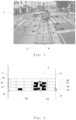
- the Figure 3 illustrates the method according to the invention for detecting a collision object 1 or a discontinuity in an image 2, which image 2 is created with a camera 13 on a rail-bound vehicle 10.
- the computing unit for analyzing the image 2 is arranged in the vehicle 10.
- the rail-bound vehicle 10 is moved on lane 3, which lane 3 is laterally limited by the rails 15 of track 11.
- the method according to the invention is characterized in that at least the lane 3 is detected as an observation area 4 in the image 2 by means of a computing unit.
- the observation area 4 follows in particular as in the Figure 3 shown the arched shape of the rails 15. It is the observation area 4 in the Figure 3 represented by dashed lines.
- FIG. 3 shows the special case that in Figure 2, in addition to the rails 15 of lane 3, further rails 16 are shown.
- the method according to the invention can be Assuming that the camera axis 14 does not exhibit any major lateral displacement, the rails 15 arranged in the center of the image are considered to be the rails of lane 3.
- the image is available in FHD resolution (1920x1080 pixels).
- the persons 18, 19 can be recognized as non-lane objects.
- Figure 3 the persons 18, 19 are marked with square brackets [ ] and each with a reference symbol.
- the gap 20 between two concrete slabs is also recognized as a discontinuity in the observation area 4.
- the method according to the invention is particularly concerned with, and in addition to the formulated tasks, the task of providing a method for the efficient detection of relevant possible collision object 1 and a relevant discontinuity.
- the computing unit determines the number of adjacent or neighboring lines with an object pixel. With reference to the Figure 3 It is determined over which number of adjacent and thus subsequent rows the person 18 or the person 19 extends as non-lane objects. Likewise, it is determined over which number of rows the gap 20 extends as a non-lane object.
- the determined number of lines, the number of lines over which the non-lane object extends, is compared with a threshold value.
- the threshold value can be set by the user, as explained in the description of the invention, or by a mathematical calculation.
- an object outside the lane such as the person 18, is classified as a collision object 1 if adjacent object pixels of this object outside the lane are detected in a number of consecutive lines greater than or equal to a threshold value.
- the method according to the invention can provide the technical effect of using the limited computing power of the computing unit arranged in the vehicle 10 to predict a collision between the vehicle 10 and the person 18.
- person 19 is identified as a potentially relevant collision object.
- the method according to the invention is therefore not limited to the evaluation of objects extending exclusively within lane 3. Person 19, as an object, extends beyond lane 3.
- the method according to the invention can have the technical effect that no computing power of the computing unit arranged in the vehicle 10 is applied to predicting a collision of the vehicle 10 with the gap 20.
- the method according to the invention can be characterized in that a central axis 6 of the observation area 4 is determined in the computing unit, wherein the non-lane object is determined by a line-by-line analysis of the sub-areas of the observation area 4 symmetrically about the central axis 6.
- This special form is in the Figure 3 entered by the arrows 5.
- the right rail 15, as a form of lateral boundary of the lane 3 or the observation area 4 mentioned here as an example, may not be detectable in a line. Since the center line 6 is in the middle of the lane 3 and thus of the observation area 4, the distance between the center line 6 and the right rail 15. The line-by-line analysis between the center line 6 and the right rail 15 can be limited by the distance measured between the center line 6 and the left rail 15.
- every nth row (as specified above) of the observation area 4 can be analyzed. If a rail 15 is not detectable in a row, the position of the rail 15 in this row can be estimated using a smoothing function, taking into account other known positions of the rail 15.
- the method according to the invention is characterized in that the application of the smoothing function has no particular influence on the result of the method according to the invention.
- the method according to the invention can be characterized in that the lane 3 is detected by lateral markings 7 of the lane 3.
- the rails 15 can be regarded as markings 7 of the lane 3.
- the method according to the invention can be characterized in that an observation area 4 is defined that is larger than the lane 3, which is Figure 2 is not shown.
- the observation area 4 can be defined on its right side by the concrete slab edge 17.
- the Figure 3 shows a scene of a vehicle 10 approaching an intersection at a time t1.
- the vehicle 10 will probably reduce its speed at the time t1, whereby the vehicle 10 will have a lower speed at a subsequent time t2. speed than at time t1.
- the method according to the invention can be carried out at a first time t1 using a limit value n1 and at a time t2 using a limit value n2. It can apply that nl ⁇ n2.
- Figure 4 shows a table, where a table field symbolizes a pixel of image 2. Furthermore, the center line 6 and the markings 7 are shown as lines in the Figure 4 registered.
- the Figure 4 The table entered comprises four rows 21, 22, 23, 24. A rectangle of a row 21, 22, 23, 24 symbolizes a pixel of image 2.
- the first row 21 is analyzed by analyzing the pixels of the first row 21, entered as rectangles, following the first direction 25 from the starting point 8.
- the pixels of the second row 22 are analyzed in the second direction 26.
- the pixels of the third row 23 are analyzed in the third direction 27.
- the pixels of the fourth row 28 are analyzed following the fourth direction 28.
- the area of image 2 displayed by rows 21 to 24 is analyzed row by row, preferably in alternating directions.
- a lane pixel of lane 3 differs from an object pixel of an object outside the lane.
- Numerous methods are known in the state of the art that provide a distinction between a lane 3 and an object outside the lane.
- the method according to the invention introduces the criterion described above and presented here again in addition in order to reliably detect objects outside the lane.
- the objects outside the lane can, if necessary, be detected as collision objects 1 using further methods according to the prior art.
- the method according to the invention pursues the particular goal of detecting pixels incorrectly classified as object pixels as such.
- the pixels identified as object pixels using state-of-the-art methods comprise a filled rectangle.
- the method according to the invention is illustrated using the example of a soccer ball 29.
- the soccer ball 29 has a size such that the soccer ball 29 is represented by at least three adjacent lines in image 2.
- a soccer ball represented by fewer lines would be Vehicle 10 is too far away and would in no way represent a collision object 1.
- an object outside the lane is classified as a collision object 1 if adjacent object pixels of this object outside the lane, in this case the soccer ball 29, are detected in a number of consecutive rows greater than or equal to a threshold value, in this case three.
- a threshold value in this case three.
- Figure 4 The football 29 shown, whose object pixels extend over three lines, is recognized as a possible collision object 1.
- a further object 30, which further object extends only over one line and thus over less than three lines, is recognized in the computing unit as not a possible collision object 1.
- the user can specify the limit value from three lines here.
- the limit value can also be set depending on the object detected using state-of-the-art methods.
- the computing unit can be connected to a database in which limit values are stored, which limit values are assigned to an object detected using a state-of-the-art method.
- the extension can, for example, be the number of sub-areas in the horizontal direction and/or vertical direction and/or the total number of sub-areas with a pixel of the football 29.
- the number of sub-areas in the vertical direction and/or in the horizontal direction can correspond to the height or width of the object outside the lane.
- the method according to the invention may include comparing the extension with a threshold extension.
- the computing unit classifies the soccer ball 29, as the non-lane object, as a collision object if the extension is greater than or equal to the threshold extension.
- the computing unit classifies the soccer ball 29, as the non-lane object, as not a collision object if the extension is less than the threshold extension.
- Figure 4 a picture 2 at a first time and the Figure 5 an image 2 at a second time. It can be the Figure 4 Figure 2 shown can be analyzed using a first limit value of three lines, for example. Furthermore, the method according to the invention can be applied to the Figure 5 The method shown may be applied, wherein a second threshold value of, for example, four lines is applied. The first time point may be before the second time point. For example, it may be detected that the distance between the soccer ball 29 and the camera 13 is reduced between the first time point and the second time point.
- the Figure 6 shows a camera 13 (see Figure 1 ) created image 2.
- the image includes lane 3 of vehicle 10 (see Figure 1 ) and a collision object 1 located in lane 3. It is irrelevant whether the collision object 1 is on lane 3 or in the lane marked Figure 6 shown projection.
- the method discussed serves to efficiently detect a collision object 1 or a discontinuity in the image 2.
- Detecting a collision object 1 comprises detecting the object in the lane 3 and classifying the object as a collision object 1.
- a first step the lane 3 in which the vehicle 11 is moving is detected.
- lane 3 can be defined by the tracks 11. Furthermore, an observation area 4 can be defined, which observation area 4 comprises lane 3 and a lateral area adjacent to lane 3 (see also the description above). The observation area 4 is delimited laterally by boundary lines 9, which extend at a defined distance from the rails of track 11. The observation area 4 comprises lane 3.
- the area of interest can be defined by lane 3 or by observation area 4.
- the area of interest is bounded laterally by the rails of track 11 bordering lane 3 and by the boundary lines 9.
- the area of interest is limited at the bottom by the edge of the image.
- the region of interest is bounded at the top by the upper edge of the image.
- the region of interest can be bounded by a straight line parallel to the respective image edge.
- An object can be detected in lane 3 or observation area 4, or in the projection onto these 3, 4, using a computing unit, which object represents a possible collision object 1.
- a bonding box 31 is determined.
- the bonding box 31 advantageously has a larger area than the possible collision object 1.
- the area of interest can thus be defined by the areal extent of the possible collision object 1, in particular the detected areal extent of the possible collision object 1 and thus by the bonding box 31.
- the area of interest can thus be defined by the lane 3 or the observation area 4 or by the detected object as a possible collision object 1 or by its boundary surfaces 31.
- a possible embodiment of the invention is that if no object is detected in the lane 3 or in the observation area 4, the area of interest is defined by the lane 3 or the observation area 4. If an object is detected, the area of interest is defined by the boundary area 31 of the object. Area of interest is thus adapted to the respective situation.
- Image 2 can be created with camera 13 at a first resolution and transmitted to a computing unit.
- the resolution of image 2 is reduced to a second image resolution.
- This method step implies that image 2 is divided into the region of interest and a further region, with the further region being defined as the region of the image which is not defined as a region of interest.
- the further region is the sub-region of image 2 adjacent to the region of interest.
- Image 2 can be available at a second resolution.
- the area of interest can be determined in image 2.
- Another camera can be used to create image data about the area of interest at a first resolution.
- the computing unit creates image data that describes the area of interest with a first image resolution and the further area of the image with a second image resolution.
- the first image resolution is preferably higher than the second image resolution.
- the first image resolution can be the highest image resolution achievable with the camera 13 or the further camera.
- the second image resolution is preferably a minimum image resolution for analyzing the image or the further areas, if an analysis of the further areas is required.
Landscapes
- Engineering & Computer Science (AREA)
- Theoretical Computer Science (AREA)
- Physics & Mathematics (AREA)
- General Physics & Mathematics (AREA)
- Multimedia (AREA)
- Evolutionary Computation (AREA)
- Computing Systems (AREA)
- Computer Vision & Pattern Recognition (AREA)
- Artificial Intelligence (AREA)
- Databases & Information Systems (AREA)
- Health & Medical Sciences (AREA)
- General Health & Medical Sciences (AREA)
- Medical Informatics (AREA)
- Software Systems (AREA)
- Traffic Control Systems (AREA)
- Image Analysis (AREA)
Applications Claiming Priority (1)
| Application Number | Priority Date | Filing Date | Title |
|---|---|---|---|
| DE102023127625.5A DE102023127625A1 (de) | 2023-10-10 | 2023-10-10 | Verfahren zum Erkennen eines Kollisionsobjektes oder einer Diskontinuität |
Publications (1)
| Publication Number | Publication Date |
|---|---|
| EP4538986A1 true EP4538986A1 (fr) | 2025-04-16 |
Family
ID=93061683
Family Applications (1)
| Application Number | Title | Priority Date | Filing Date |
|---|---|---|---|
| EP24205456.7A Pending EP4538986A1 (fr) | 2023-10-10 | 2024-10-09 | Procédé de détection d'un objet de collision ou d'une discontinuité |
Country Status (2)
| Country | Link |
|---|---|
| EP (1) | EP4538986A1 (fr) |
| DE (1) | DE102023127625A1 (fr) |
Citations (6)
| Publication number | Priority date | Publication date | Assignee | Title |
|---|---|---|---|---|
| DE102005045017A1 (de) | 2005-09-21 | 2007-03-22 | Robert Bosch Gmbh | Verfahren und Fahrerassistenzsystem zur sensorbasierten Anfahrtsteuerung eines Kraftfahrzeugs |
| DE102013101833A1 (de) | 2012-02-29 | 2013-08-29 | Denso Corporation | Fahrsteuervorrichtung, die an einem Fahrzeug angebracht ist, um eine Kollision mit einem vorangehenden Fahrzeug zu vermeiden |
| US20190294179A1 (en) * | 2014-01-30 | 2019-09-26 | Mobileye Vision Technologies Ltd. | Systems and methods for detecting low-height objects in a roadway |
| US20190325595A1 (en) * | 2018-04-18 | 2019-10-24 | Mobileye Vision Technologies Ltd. | Vehicle environment modeling with a camera |
| DE102019003530A1 (de) | 2018-11-10 | 2020-05-14 | Günter Fendt | Verifikation der Ausdehnung der Überwachungsbereiche bzw. Erfassungscharakteristiken verschiedener Systeme |
| US20230206651A1 (en) * | 2020-09-08 | 2023-06-29 | Nvidia Corporation | Adaptive object tracking algorithm for autonomous machine applications |
-
2023
- 2023-10-10 DE DE102023127625.5A patent/DE102023127625A1/de active Pending
-
2024
- 2024-10-09 EP EP24205456.7A patent/EP4538986A1/fr active Pending
Patent Citations (6)
| Publication number | Priority date | Publication date | Assignee | Title |
|---|---|---|---|---|
| DE102005045017A1 (de) | 2005-09-21 | 2007-03-22 | Robert Bosch Gmbh | Verfahren und Fahrerassistenzsystem zur sensorbasierten Anfahrtsteuerung eines Kraftfahrzeugs |
| DE102013101833A1 (de) | 2012-02-29 | 2013-08-29 | Denso Corporation | Fahrsteuervorrichtung, die an einem Fahrzeug angebracht ist, um eine Kollision mit einem vorangehenden Fahrzeug zu vermeiden |
| US20190294179A1 (en) * | 2014-01-30 | 2019-09-26 | Mobileye Vision Technologies Ltd. | Systems and methods for detecting low-height objects in a roadway |
| US20190325595A1 (en) * | 2018-04-18 | 2019-10-24 | Mobileye Vision Technologies Ltd. | Vehicle environment modeling with a camera |
| DE102019003530A1 (de) | 2018-11-10 | 2020-05-14 | Günter Fendt | Verifikation der Ausdehnung der Überwachungsbereiche bzw. Erfassungscharakteristiken verschiedener Systeme |
| US20230206651A1 (en) * | 2020-09-08 | 2023-06-29 | Nvidia Corporation | Adaptive object tracking algorithm for autonomous machine applications |
Non-Patent Citations (2)
| Title |
|---|
| DILEK ESMA ET AL: "Computer Vision Applications in Intelligent Transportation Systems: A Survey", SENSORS, vol. 23, no. 6, 8 March 2023 (2023-03-08), CH, pages 2938, XP093243347, ISSN: 1424-8220, DOI: 10.3390/s23062938 * |
| NACHUAN MA ET AL: "Computer Vision for Road Imaging and Pothole Detection: A State-of-the-Art Review of Systems and Algorithms", ARXIV.ORG, CORNELL UNIVERSITY LIBRARY, 201 OLIN LIBRARY CORNELL UNIVERSITY ITHACA, NY 14853, 28 April 2022 (2022-04-28), XP091210204, DOI: 10.1093/TSE/TDAC026 * |
Also Published As
| Publication number | Publication date |
|---|---|
| DE102023127625A1 (de) | 2025-04-10 |
Similar Documents
| Publication | Publication Date | Title |
|---|---|---|
| EP3466239B1 (fr) | Procédé de fonctionnement d'un engin agricole automatique | |
| DE69322306T2 (de) | Gegenstandserkennungssystem mittels Bildverarbeitung | |
| DE102008034304B4 (de) | Bildverarbeitungsgerät | |
| DE102013205950B4 (de) | Verfahren zum Detektieren von Straßenrändern | |
| DE69027633T2 (de) | Automatische Fahrzeugführung entlang Führungslinien | |
| DE60224324T2 (de) | Verfahren und Vorrichtung zur Verarbeitung von Fahrzeugbildern | |
| DE102016118502A1 (de) | Verfahren, Einrichtung und Vorrichtung zum Ermitteln einer Fahrbahngrenze | |
| DE102016115371A1 (de) | Verfahren und vorrichtung zur meidung von rückwärtigem querverkehr | |
| WO2007033870A1 (fr) | Procede et systeme d'aide a la conduite pour la commande de demarrage d'un vehicule automobile basee sur un capteur | |
| WO2019057252A1 (fr) | Procédé et dispositif de détection de voies de circulation, système d'aide à la conduite et véhicule | |
| EP2107336A1 (fr) | Procédé et dispositif de reconnaissance d'image d'objets mobiles, comme par exemple dans des installations de transport | |
| EP4569494A1 (fr) | Procédé de détermination d'un emplacement de stationnement et d'une position cible pour un véhicule dans l'emplacement de stationnement | |
| EP3715779B1 (fr) | Procédé et dispositif de détermination des déformations d'un objet | |
| EP3557549B1 (fr) | Procédé d'évaluation d'un événement | |
| EP3576013A1 (fr) | Évaluation d'un parcours d'une voie ferroviaire | |
| EP4538986A1 (fr) | Procédé de détection d'un objet de collision ou d'une discontinuité | |
| DE112022002410T5 (de) | Informationsverarbeitungsvorrichtung, informationsverarbeitungsverfahren und steuerprogramm | |
| EP2254104B1 (fr) | Procédé de reconnaissance automatique d'une modification de situation | |
| DE102014214711B4 (de) | Verfahren zum Betrieb eines Assistenzsystems eines Kraftfahrzeugs sowie Assistenzsystem | |
| AT527687A1 (de) | Autonotation von neuronalen Netzen | |
| EP2219155B1 (fr) | Appareil, procédé et programme d'ordinateur pour segmentation d'un objet dans une image, et système de vidéosurveillance | |
| EP0779993B1 (fr) | Procede et dispositif permettant de detecter des objets | |
| DE102023117654B4 (de) | Verfahren zur Überwachung eines Schutzbereichs basierend auf einem Modellobjektdatensatz mit mindestens einem 3D-Modellobjekt | |
| EP4524909A1 (fr) | Chariot de manutention et procédé de détermination d'un modèle de comportement de trafic d'un autre chariot de manutention, procédé d'apprentissage d'un réseau neuronal | |
| EP4653287A1 (fr) | Évaluation en une étape d'un déroulement temporel d'un compteur d'essieux |
Legal Events
| Date | Code | Title | Description |
|---|---|---|---|
| PUAI | Public reference made under article 153(3) epc to a published international application that has entered the european phase |
Free format text: ORIGINAL CODE: 0009012 |
|
| STAA | Information on the status of an ep patent application or granted ep patent |
Free format text: STATUS: THE APPLICATION HAS BEEN PUBLISHED |
|
| AK | Designated contracting states |
Kind code of ref document: A1 Designated state(s): AL AT BE BG CH CY CZ DE DK EE ES FI FR GB GR HR HU IE IS IT LI LT LU LV MC ME MK MT NL NO PL PT RO RS SE SI SK SM TR |
|
| STAA | Information on the status of an ep patent application or granted ep patent |
Free format text: STATUS: REQUEST FOR EXAMINATION WAS MADE |
|
| 17P | Request for examination filed |
Effective date: 20251013 |