EP4541994A1 - Klammerstruktur, rahmenlose fahrzeugtür und fahrzeug - Google Patents
Klammerstruktur, rahmenlose fahrzeugtür und fahrzeug Download PDFInfo
- Publication number
- EP4541994A1 EP4541994A1 EP23842386.7A EP23842386A EP4541994A1 EP 4541994 A1 EP4541994 A1 EP 4541994A1 EP 23842386 A EP23842386 A EP 23842386A EP 4541994 A1 EP4541994 A1 EP 4541994A1
- Authority
- EP
- European Patent Office
- Prior art keywords
- glass
- bracket structure
- support
- component
- structure according
- Prior art date
- Legal status (The legal status is an assumption and is not a legal conclusion. Google has not performed a legal analysis and makes no representation as to the accuracy of the status listed.)
- Pending
Links
Images




Classifications
-
- B—PERFORMING OPERATIONS; TRANSPORTING
- B60—VEHICLES IN GENERAL
- B60J—WINDOWS, WINDSCREENS, NON-FIXED ROOFS, DOORS, OR SIMILAR DEVICES FOR VEHICLES; REMOVABLE EXTERNAL PROTECTIVE COVERINGS SPECIALLY ADAPTED FOR VEHICLES
- B60J5/00—Doors
- B60J5/04—Doors arranged at the vehicle sides
- B60J5/0412—Lower door structure
- B60J5/0416—Assembly panels to be installed in doors as a module with components, e.g. lock or window lifter, attached thereto
-
- E—FIXED CONSTRUCTIONS
- E05—LOCKS; KEYS; WINDOW OR DOOR FITTINGS; SAFES
- E05F—DEVICES FOR MOVING WINGS INTO OPEN OR CLOSED POSITION; CHECKS FOR WINGS; WING FITTINGS NOT OTHERWISE PROVIDED FOR, CONCERNED WITH THE FUNCTIONING OF THE WING
- E05F11/00—Man-operated mechanisms for operating wings, including those which also operate the fastening
- E05F11/38—Man-operated mechanisms for operating wings, including those which also operate the fastening for sliding windows, e.g. vehicle windows, to be opened or closed by vertical movement
- E05F11/382—Man-operated mechanisms for operating wings, including those which also operate the fastening for sliding windows, e.g. vehicle windows, to be opened or closed by vertical movement for vehicle windows
- E05F11/385—Fixing of window glass to the carrier of the operating mechanism
-
- B—PERFORMING OPERATIONS; TRANSPORTING
- B60—VEHICLES IN GENERAL
- B60J—WINDOWS, WINDSCREENS, NON-FIXED ROOFS, DOORS, OR SIMILAR DEVICES FOR VEHICLES; REMOVABLE EXTERNAL PROTECTIVE COVERINGS SPECIALLY ADAPTED FOR VEHICLES
- B60J1/00—Windows; Windscreens; Accessories therefor
- B60J1/004—Mounting of windows
-
- B—PERFORMING OPERATIONS; TRANSPORTING
- B60—VEHICLES IN GENERAL
- B60J—WINDOWS, WINDSCREENS, NON-FIXED ROOFS, DOORS, OR SIMILAR DEVICES FOR VEHICLES; REMOVABLE EXTERNAL PROTECTIVE COVERINGS SPECIALLY ADAPTED FOR VEHICLES
- B60J1/00—Windows; Windscreens; Accessories therefor
- B60J1/08—Windows; Windscreens; Accessories therefor arranged at vehicle sides
- B60J1/12—Windows; Windscreens; Accessories therefor arranged at vehicle sides adjustable
- B60J1/16—Windows; Windscreens; Accessories therefor arranged at vehicle sides adjustable slidable
- B60J1/17—Windows; Windscreens; Accessories therefor arranged at vehicle sides adjustable slidable vertically
-
- B—PERFORMING OPERATIONS; TRANSPORTING
- B60—VEHICLES IN GENERAL
- B60J—WINDOWS, WINDSCREENS, NON-FIXED ROOFS, DOORS, OR SIMILAR DEVICES FOR VEHICLES; REMOVABLE EXTERNAL PROTECTIVE COVERINGS SPECIALLY ADAPTED FOR VEHICLES
- B60J5/00—Doors
- B60J5/04—Doors arranged at the vehicle sides
- B60J5/048—Doors arranged at the vehicle sides characterised by the material
-
- B—PERFORMING OPERATIONS; TRANSPORTING
- B60—VEHICLES IN GENERAL
- B60J—WINDOWS, WINDSCREENS, NON-FIXED ROOFS, DOORS, OR SIMILAR DEVICES FOR VEHICLES; REMOVABLE EXTERNAL PROTECTIVE COVERINGS SPECIALLY ADAPTED FOR VEHICLES
- B60J5/00—Doors
- B60J5/04—Doors arranged at the vehicle sides
- B60J5/0493—Appurtenances
-
- E—FIXED CONSTRUCTIONS
- E05—LOCKS; KEYS; WINDOW OR DOOR FITTINGS; SAFES
- E05F—DEVICES FOR MOVING WINGS INTO OPEN OR CLOSED POSITION; CHECKS FOR WINGS; WING FITTINGS NOT OTHERWISE PROVIDED FOR, CONCERNED WITH THE FUNCTIONING OF THE WING
- E05F11/00—Man-operated mechanisms for operating wings, including those which also operate the fastening
- E05F11/38—Man-operated mechanisms for operating wings, including those which also operate the fastening for sliding windows, e.g. vehicle windows, to be opened or closed by vertical movement
- E05F11/382—Man-operated mechanisms for operating wings, including those which also operate the fastening for sliding windows, e.g. vehicle windows, to be opened or closed by vertical movement for vehicle windows
- E05F11/385—Fixing of window glass to the carrier of the operating mechanism
- E05F2011/387—Fixing of window glass to the carrier of the operating mechanism using arrangements in the window glass, e.g. holes
Definitions
- frameless vehicle doors are more and more used in vehicles (e.g., coupes).
- the frameless vehicle doors have higher technological requirements for rubber strips, guide rails and even lifting mechanisms, and it is also necessary to automatically control the rise and fall of the glass each time the door is opened or closed.
- An objective of the present disclosure is to provide a bracket structure, a frameless vehicle door, and a vehicle, which can finely tune an offset of glass through a bracket, thereby lowering the fitness requirement of the frameless vehicle door on the glass, and improving the yield.
- Another objective of the present disclosure is to provide a bracket structure, a frameless vehicle door, and a vehicle, which can save the complicated operations on the tape of the bracket in the process of assembling the glass, improve the mounting efficiency, and reduce the labor consumption.
- the present disclosure provides a bracket structure for supporting and positioning glass of a vehicle window, in which the bracket structure includes a support member and an adjustment member, the support member is provided with a first support wall and a second support wall which are opposite to each other, a support groove is formed between the first support wall and the second support wall, a bottom of the glass is disposed in the support groove, the adjustment member is connected to the first support wall, and the adjustment member has an amount of deformation towards the glass and pushes and presses the first support wall to apply a pressure to the glass, so that a top of the glass can be attached and fitted with a sealing strip on a vehicle body.
- the present disclosure provides a frameless vehicle door, including glass and the aforementioned bracket structure, a bottom of the glass is disposed on the bracket structure, and the bracket structure can apply a pressure to the glass, so that a top of the glass is fitted and clamped with a sealing strip on a vehicle body.
- the present disclosure provides a vehicle, including the aforementioned frameless vehicle door.
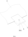
- the present disclosure provides a bracket structure for supporting and positioning glass 3 of a vehicle window;
- the bracket structure includes a support member 1 and an adjustment member 2;
- the top of the support member 1 is vertically provided with a first support wall 102 and a second support wall 103 which are opposite to each other;
- a support groove 101 is formed between the first support wall 102 and the second support wall 103;
- the bottom of the glass 3 is fixedly disposed in the support groove 101;
- the adjustment member 2 is connected to the first support wall 102; since the adjustment member 2 has an amount of deformation towards the glass 3, the adjustment member 2 can push and press the first support wall 102 to apply a pressure to the glass 3, and then finely tunes an offset of the glass 3, so that the glass 3 rising to a highest position can be attached and fitted with a sealing strip on a vehicle body, which lowers the requirement of the glass 3 itself on the fitness and improves the yield.
- the support member 1 is made of plastic to facilitate, while the adjustment member 2 is made of metal to increase the overall strength of the bracket structure.
- the use of plastic material of support member 1 facilitates the assembly and fixation of glass 3.
- the plastic used for the support member 1 is specifically PBT-GF30, and the metal used for the adjustment member 2 is specifically DD13 Zn/Ni.
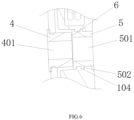
- the adjustment member 2 is provided with a first component 4 that is provided with a threaded hole 401
- the support member 1 is provided with a second component 5 that is provided with a through hole 501 communicated with the threaded hole 401
- a bolt of the lifter is screwed into the threaded hole 401, and a distance between the first component 4 and the second component 5 can be adjusted by adjusting the position of the bolt in the threaded hole 401 (i.e., a tightening degree of the bolt), so that the first component 4 drives the adjustment member 2 to produce a displacement, and the adjustment member 2 and the first support wall 102 apply a pressure to the glass 3; the glass 3 can produce an offset under the pressure, so that fine tuning of the glass 3 is achieved.
- the first component 4 is a polygonal barrel-shaped structural member
- the adjustment member 2 is provided with a second mounting hole opposite to a first mounting hole
- the first component 4 is embedded in the second mounting hole and clamped and fixed with the second mounting hole.
- the second component 5 is a cylindrical structural member.
- the first mounting hole is disposed on the support member 1 and below the support groove 101.
- the second component 5 is embedded in the first mounting hole, and at least one annular anti-detachment boss 502 is disposed on an outer wall of the second component 5 along a circumference thereof.
- An inner wall of the first mounting hole is provided with a clamping groove 104 fitted with the anti-detachment boss 502.
- the anti-detachment boss 502 is fitted and clamped with the clamping groove 104, so that when the second component 5 is axially stressed, the mounting stability of the second component 5 can be improved and the second component 5 can be prevented from dropping off the first mounting hole, in which the first component 4 can be, but is not limited to, a nut.
- the second component 5 may also be connected to the support member 1 in other connection modes, such as welding or integral injection molding, and the specific connection mode is not limited in the present disclosure.
- the hardness of the first component 4 is greater than that of the second component 5, and a first gap 6 is reserved between the first component 4 and the second component 5 in the assembled state. Since being provided with the threaded hole 401, the first component 4 is tightened into the threaded hole 401 by the bolt on the lifter during final assembly, thereby assembling the lifter and the bracket structure. In the process of screwing the bolt, under the tightening force of the bolt, the first component 4 moves towards the second component 5, even to a position where the first component 4 abuts against the second component 5 (at this time, the first gap 6 is not existed).
- the second component 5 Since the hardness of the first component 4 is greater than that of the second component 5, the second component 5 is slightly deformed after being pressed by the first component 4.
- the second component 5 is disposed between the first component 4 and the lifter, so that the first component 4 can be prevented from being directly contacted with the lifter and then damaged under stress, thereby supporting, buffering and protecting the first component 4 (the function of the second component 5 is similar to that of laying a soft washer at the bottom when the screw is tightened), and also preventing the first component 4 from being loosened.
- the arrangement of the second component 5 can also compensate for the irregularity of the surface of the support member 1.
- the first gap 6 exemplarily has a width of 0.15 mm to 0.25 mm.
- the material of the first component 4 can be but not limited to stainless steel, and the material of the second component 5 can be but not limited to copper (e.g., brass H59).
- a diameter of the through hole 501 is larger than that of the threaded hole 401, and during screwing, an end of the bolt can pass through the through hole 501 and extend into the threaded hole 401 to be screwed and fixed.
- the adjustment member 2 is a plate-shaped structure with a radian, and the shape thereof is adapted to that of the first support wall 102; the adjustment member 2 covers a surface of the first support wall 102 facing away from the glass 3, and a second clearance 7 is formed between a middle portion of the adjustment member 2 and the surface of the first support wall 102 facing away from the glass 3.
- the top of the adjustment member 2 abuts against the surface of the first support wall 102 facing away from the glass 3, so that the top of the adjustment member 2 can apply a pressure to the top of the first support wall 102, so that the first support wall 102 can extrude the glass 3 to finely tune the offset of the glass 3.
- buckles 105 are respectively disposed at the corners of the first support wall 102 of the support member 1, and the buckles 105 each clamps the edge of the adjustment member 2, so that the adjustment member 2 is connected to the support member 1 through the buckles 105.
- rectangular notches 106 are formed on both sides of the top of the support member 1 and close to the buckle 105.
- the support member 1 is made of plastic and the adjustment member 2 is made of metal, stable assembly can only be realized by extruding the support member 1 to be deformed, and since the support member 1 itself has high hardness, the support member 1 is not easy to be deformed even if it has a certain thickness.
- the notches 106 are formed in the support member 1, thereby increasing the deformation capability of the support member 1 at the position close to the buckle 105 and achieving a smooth assembly.
- a vertical length of the first support wall 102 is greater than that of the second support wall 103, and an upper portion of a surface on a side of the first support wall 102 facing the glass 3 is provided with a pressing member 8, which is in interference fit with the glass 3 in the assembled state, so as to apply a pressing force to the glass 3.
- the pressing member 8 is a layered structure covering the surface of the first support wall 102.
- the pressing member 8 is exemplarily made of a thermoplastic elastomer (TPE).
- TPE thermoplastic elastomer
- the pressing member 8 is added to the support member 1 by secondary injection molding or double injection molding, and the pressing member 8 interferes with an outer surface of the glass 3.
- the interference amount will produce a pressing force on the outer surface of the glass 3, which not only enables the first support wall 102 to be more closely attached to the glass 3, but also applies a pressure on the glass 3 towards the inner side of the vehicle window after the assembly, thereby achieving the effect of fine tuning the offset of the glass 3.
- the interference amount of the pressing member 8 on the glass 3 is between 0.5 mm and 1.5 mm.
- a bonding portion 9 is disposed between the two opposite inner walls of the support groove 101 and between the bottom wall of the support groove 101 and the glass 3.
- the glass 3 is bonded in the support groove 101 through the bonding portion 9, and the assembly of the glass 3 is ensured to be more stable by bonding three surfaces of the glass 3.
- the bonding portion 9 is made of adhesive glue, which may adopt ordinary one-component polyurethane glue, two-component polyurethane glue or thermosetting polyurethane glue.
- adhesive glue which may adopt ordinary one-component polyurethane glue, two-component polyurethane glue or thermosetting polyurethane glue.
- the two-component polyurethane glue and the thermosetting polyurethane glue are exemplary.
- the first support wall 102 can increase the contact area between the support member 1 and the glass 3, and reduce the stress borne by the supporting part of the support member 1 during the travelling of the vehicle, while the second support wall 103 is convenient for the injection of the adhesive glue to ensure that the support groove 101 can be fully filled with the adhesive glue.
- the adhesive glue it is necessary to ensure that the adhesive glue does not exceed the pressing member 8, so as to avoid the failure of the pressing member 8 due to excessive adhesive glue.
- a fourth gap 10 for disposing the bonding portion 9 is reserved between the two opposite inner walls of the support groove 101 and between the bottom wall of the support groove 101 and the glass 3.
- the bonding portion 9 can be bonded with three surfaces of the glass 3 to form a U-shaped bonding portion 9, which effectively increases the glue storage and ensures the stable bonding of the glass 3.
- a plurality of reinforcing ribs 1011 extending vertically are disposed on the inner wall of the support groove 101, the reinforcing ribs 1011 are arranged side by side at intervals in a horizontal direction, and a third gap (a part of the fourth gap 10) is reserved between the reinforcing rib 1011 and the glass 3.
- the arrangement of the reinforcing ribs 1011 on the one hand, prevents the glass 3 and the support member 1 from being displaced after the assembly, and on the other hand, promotes the glue storage and improves the stability of the bonding between the glass 3 and the support member 1.
- a width of the third gap can be, but not limited to, 0.2 mm to 1 mm.
- the adjustment member 2 is mounted externally, and the adjustment member 2 and the support member 1 are assembled and fixed through the buckle 105, with a movement margin maintained between the adjustment member 2 and the support member 1 after the assembly (i.e., the first gap 6 is reserved between the first component 4 and the second component 5); when the assembled glass is loaded, in the process of screwing the bolt on the lifter and the first component 4 on the adjustment member 2, there is interference between the pressing member 8 and the surface of the glass 3 and the adjustment member 2 is attached to the first support wall 102 on the support member 1. Therefore, during the assembly, the pressure applied on the glass 3 by the first support wall 102 can be adjusted by adjusting the tightening degree of the bolt in the threaded hole on the first component 4, so as to adjust the inward offset of the top of the glass 3.
- the present disclosure provides a frameless vehicle door, which includes a glass 3 and the aforementioned bracket structure, in which the bottom of the glass 3 is fixedly disposed on the bracket structure, and the bracket structure can apply a pressure to the glass 3, so that the top of the glass 3 is fitted and clamped with a sealing strip on a vehicle body.
- the glass 3 can be made of, but not limited to, tempered glass or semi-tempered laminated glass, in which the semi-toughened laminated glass is exemplary.
- the present disclosure provides a vehicle which includes the aforementioned frameless vehicle door.
Landscapes
- Engineering & Computer Science (AREA)
- Mechanical Engineering (AREA)
- Window Of Vehicle (AREA)
Applications Claiming Priority (2)
| Application Number | Priority Date | Filing Date | Title |
|---|---|---|---|
| CN202210859255.8A CN115071387B (zh) | 2022-07-21 | 2022-07-21 | 托架结构、无框车门及车辆 |
| PCT/CN2023/108354 WO2024017324A1 (zh) | 2022-07-21 | 2023-07-20 | 托架结构、无框车门及车辆 |
Publications (2)
| Publication Number | Publication Date |
|---|---|
| EP4541994A1 true EP4541994A1 (de) | 2025-04-23 |
| EP4541994A4 EP4541994A4 (de) | 2025-10-22 |
Family
ID=83241972
Family Applications (1)
| Application Number | Title | Priority Date | Filing Date |
|---|---|---|---|
| EP23842386.7A Pending EP4541994A4 (de) | 2022-07-21 | 2023-07-20 | Klammerstruktur, rahmenlose fahrzeugtür und fahrzeug |
Country Status (5)
| Country | Link |
|---|---|
| EP (1) | EP4541994A4 (de) |
| JP (1) | JP2025523076A (de) |
| KR (1) | KR20250022848A (de) |
| CN (1) | CN115071387B (de) |
| WO (1) | WO2024017324A1 (de) |
Families Citing this family (1)
| Publication number | Priority date | Publication date | Assignee | Title |
|---|---|---|---|---|
| CN115071387B (zh) * | 2022-07-21 | 2024-12-03 | 福耀玻璃工业集团股份有限公司 | 托架结构、无框车门及车辆 |
Family Cites Families (20)
| Publication number | Priority date | Publication date | Assignee | Title |
|---|---|---|---|---|
| US5363595A (en) * | 1993-12-28 | 1994-11-15 | General Motors Corporation | Arrangement of a vehicle door with extendable window |
| US5809695A (en) * | 1997-01-27 | 1998-09-22 | Hi-Lex Corporation | Window regulator |
| DE19956756C2 (de) * | 1999-11-25 | 2002-12-12 | Brose Fahrzeugteile | Einstellbarer Mitnehmer für einen Fensterheber einer rahmenlosen Fahrzeugtür |
| US6598345B1 (en) * | 2001-08-22 | 2003-07-29 | Hi-Lex Corporation | Window regulator having a cam member for lateral adjustment |
| ITTO20020615A1 (it) * | 2002-07-15 | 2004-01-15 | Lames Spa | Pattino di sollevamento per alzacristalli di autoveicoli ed alzacristallo comprendente tale pattino |
| ES1058415Y (es) * | 2004-08-18 | 2005-04-01 | Castellon Melchor Daumal | Elevalunas regulable para vehiculos automoviles. |
| JP2008162442A (ja) * | 2006-12-28 | 2008-07-17 | Mitsubishi Motors Corp | ドアガラスの支持構造 |
| ES2692541T3 (es) * | 2012-03-30 | 2018-12-04 | Küster Holding GmbH | Dispositivo de fijación para fijar una luna de ventanilla dentro de una carrocería de un vehículo automóvil |
| CN206190102U (zh) * | 2016-04-11 | 2017-05-24 | 宁波职业技术学院 | 一种汽车车窗玻璃升降机构 |
| IT201700110189A1 (it) * | 2017-10-02 | 2019-04-02 | Hi Lex Italy S P A | Dispositivo di regolazione della posizione del vetro di un alzacristallo di un autoveicolo. |
| CN208089089U (zh) * | 2018-04-16 | 2018-11-13 | 温州豪华汽车配件有限公司 | 一种玻璃升降器托架 |
| DE102019131998A1 (de) * | 2018-11-29 | 2020-06-04 | Magna Closures Inc. | Verstellbare hebeplatte für rahmenlose tür |
| CN109555398A (zh) * | 2019-01-21 | 2019-04-02 | 河北科力汽车零部件有限公司 | 一种能够与车窗玻璃快速粘结固化的托架 |
| FR3095988B1 (fr) * | 2019-05-13 | 2021-09-24 | Saint Gobain | Vitrage a porte-vitre en deux parties et procede de fabrication dudit vitrage |
| JP6854391B1 (ja) * | 2020-04-24 | 2021-04-07 | リッチコミュニケーションズ株式会社 | 自動車用ドアガラスホルダ |
| CN111810017A (zh) * | 2020-06-08 | 2020-10-23 | 浙江零跑科技有限公司 | 一种可调节的无框玻璃升降器托盘结构 |
| CN213649302U (zh) * | 2020-11-23 | 2021-07-09 | 重庆海德世拉索系统(集团)有限公司 | 一种车门无框玻璃的夹紧装置 |
| CN215632413U (zh) * | 2021-06-15 | 2022-01-25 | 江苏金彭集团有限公司 | 一种新型绳轮式玻璃升降器结构 |
| CN113525041B (zh) * | 2021-06-22 | 2023-05-16 | 福耀玻璃工业集团股份有限公司 | 托架、透光组件及车辆 |
| CN115071387B (zh) * | 2022-07-21 | 2024-12-03 | 福耀玻璃工业集团股份有限公司 | 托架结构、无框车门及车辆 |
-
2022
- 2022-07-21 CN CN202210859255.8A patent/CN115071387B/zh active Active
-
2023
- 2023-07-20 WO PCT/CN2023/108354 patent/WO2024017324A1/zh not_active Ceased
- 2023-07-20 JP JP2025501631A patent/JP2025523076A/ja active Pending
- 2023-07-20 EP EP23842386.7A patent/EP4541994A4/de active Pending
- 2023-07-20 KR KR1020257001348A patent/KR20250022848A/ko active Pending
Also Published As
| Publication number | Publication date |
|---|---|
| JP2025523076A (ja) | 2025-07-17 |
| CN115071387B (zh) | 2024-12-03 |
| WO2024017324A1 (zh) | 2024-01-25 |
| KR20250022848A (ko) | 2025-02-17 |
| EP4541994A4 (de) | 2025-10-22 |
| CN115071387A (zh) | 2022-09-20 |
Similar Documents
| Publication | Publication Date | Title |
|---|---|---|
| US8656646B2 (en) | Vehicle door | |
| US8839589B2 (en) | Automotive glazing and component assembly | |
| US9994094B2 (en) | Profile element for connecting a vehicle window pane to a cover part and profile element assembly | |
| KR101877146B1 (ko) | 차량 창문용 밀폐 배열체 | |
| EP4541994A1 (de) | Klammerstruktur, rahmenlose fahrzeugtür und fahrzeug | |
| CA2910935C (en) | Sealing arrangement for a motor vehicle window pane | |
| US11333391B2 (en) | Air port component and air conditioner | |
| US8079185B2 (en) | Window element for insertion in a window aperture in an outer skin of a transport | |
| DE19843843A1 (de) | Fensterscheibe mit einem eine Spaltabdeckung umfassenden Profilstrang | |
| CN101678740B (zh) | 通过粘接将玻璃装配到其支撑物上的方法及实施该方法的装置 | |
| CN1809680B (zh) | 内玻璃支架 | |
| US8100468B2 (en) | Connecting structure of resin panel and stiffener for vehicle | |
| EP4357178A1 (de) | Fahrzeugsonnendachvorrichtung und fensterscheibenanordnung dafür | |
| CN116550537B (zh) | 挡料组件和涂布机 | |
| CN214492490U (zh) | 平面减震密封门及平面减震密封汽车车门 | |
| US10894465B2 (en) | Seal assembly for automotive door module | |
| CN108799270B (zh) | 车辆安装件组件和具有其的车辆 | |
| EP4335673A1 (de) | Dreieckige fensteranordnung und kraftfahrzeug mit derselben | |
| CN223278868U (zh) | 一种支架总成、车辆玻璃总成及车辆 | |
| US20240239161A1 (en) | Fixed roof element for a vehicle roof, comprising a guide rail or other element of a shading system | |
| CN110168183A (zh) | 节能门窗组件 | |
| KR200226335Y1 (ko) | 유리 두께 조절이 가능한 창틀용 샤시 | |
| US20240123801A1 (en) | Corner cover, sealing assembly and method of installing the corner cover | |
| CN218295865U (zh) | 吸油烟机用开关盖板的安装结构 | |
| JPS60219181A (ja) | クオ−タウインドガラスの取付け方法 |
Legal Events
| Date | Code | Title | Description |
|---|---|---|---|
| STAA | Information on the status of an ep patent application or granted ep patent |
Free format text: STATUS: THE INTERNATIONAL PUBLICATION HAS BEEN MADE |
|
| PUAI | Public reference made under article 153(3) epc to a published international application that has entered the european phase |
Free format text: ORIGINAL CODE: 0009012 |
|
| STAA | Information on the status of an ep patent application or granted ep patent |
Free format text: STATUS: REQUEST FOR EXAMINATION WAS MADE |
|
| 17P | Request for examination filed |
Effective date: 20250114 |
|
| AK | Designated contracting states |
Kind code of ref document: A1 Designated state(s): AL AT BE BG CH CY CZ DE DK EE ES FI FR GB GR HR HU IE IS IT LI LT LU LV MC ME MK MT NL NO PL PT RO RS SE SI SK SM TR |
|
| A4 | Supplementary search report drawn up and despatched |
Effective date: 20250918 |
|
| RIC1 | Information provided on ipc code assigned before grant |
Ipc: E05F 15/689 20150101AFI20250912BHEP Ipc: B60J 5/04 20060101ALI20250912BHEP Ipc: B60J 1/17 20060101ALI20250912BHEP Ipc: B60J 1/00 20060101ALI20250912BHEP Ipc: E05F 11/38 20060101ALI20250912BHEP |
|
| DAV | Request for validation of the european patent (deleted) | ||
| DAX | Request for extension of the european patent (deleted) |