EP4543183A1 - Modul zur thermoelektrischen erzeugung und einheit zur thermoelektrischen erzeugung - Google Patents
Modul zur thermoelektrischen erzeugung und einheit zur thermoelektrischen erzeugung Download PDFInfo
- Publication number
- EP4543183A1 EP4543183A1 EP23852496.1A EP23852496A EP4543183A1 EP 4543183 A1 EP4543183 A1 EP 4543183A1 EP 23852496 A EP23852496 A EP 23852496A EP 4543183 A1 EP4543183 A1 EP 4543183A1
- Authority
- EP
- European Patent Office
- Prior art keywords
- base material
- power generation
- joint part
- thermoelectric power
- generation module
- Prior art date
- Legal status (The legal status is an assumption and is not a legal conclusion. Google has not performed a legal analysis and makes no representation as to the accuracy of the status listed.)
- Withdrawn
Links
Images


Classifications
-
- H—ELECTRICITY
- H10—SEMICONDUCTOR DEVICES; ELECTRIC SOLID-STATE DEVICES NOT OTHERWISE PROVIDED FOR
- H10N—ELECTRIC SOLID-STATE DEVICES NOT OTHERWISE PROVIDED FOR
- H10N10/00—Thermoelectric devices comprising a junction of dissimilar materials, i.e. devices exhibiting Seebeck or Peltier effects
- H10N10/10—Thermoelectric devices comprising a junction of dissimilar materials, i.e. devices exhibiting Seebeck or Peltier effects operating with only the Peltier or Seebeck effects
- H10N10/17—Thermoelectric devices comprising a junction of dissimilar materials, i.e. devices exhibiting Seebeck or Peltier effects operating with only the Peltier or Seebeck effects characterised by the structure or configuration of the cell or thermocouple forming the device
-
- H—ELECTRICITY
- H10—SEMICONDUCTOR DEVICES; ELECTRIC SOLID-STATE DEVICES NOT OTHERWISE PROVIDED FOR
- H10N—ELECTRIC SOLID-STATE DEVICES NOT OTHERWISE PROVIDED FOR
- H10N10/00—Thermoelectric devices comprising a junction of dissimilar materials, i.e. devices exhibiting Seebeck or Peltier effects
- H10N10/10—Thermoelectric devices comprising a junction of dissimilar materials, i.e. devices exhibiting Seebeck or Peltier effects operating with only the Peltier or Seebeck effects
- H10N10/13—Thermoelectric devices comprising a junction of dissimilar materials, i.e. devices exhibiting Seebeck or Peltier effects operating with only the Peltier or Seebeck effects characterised by the heat-exchanging means at the junction
-
- H—ELECTRICITY
- H10—SEMICONDUCTOR DEVICES; ELECTRIC SOLID-STATE DEVICES NOT OTHERWISE PROVIDED FOR
- H10N—ELECTRIC SOLID-STATE DEVICES NOT OTHERWISE PROVIDED FOR
- H10N10/00—Thermoelectric devices comprising a junction of dissimilar materials, i.e. devices exhibiting Seebeck or Peltier effects
- H10N10/80—Constructional details
- H10N10/81—Structural details of the junction
- H10N10/817—Structural details of the junction the junction being non-separable, e.g. being cemented, sintered or soldered
-
- H—ELECTRICITY
- H10—SEMICONDUCTOR DEVICES; ELECTRIC SOLID-STATE DEVICES NOT OTHERWISE PROVIDED FOR
- H10N—ELECTRIC SOLID-STATE DEVICES NOT OTHERWISE PROVIDED FOR
- H10N10/00—Thermoelectric devices comprising a junction of dissimilar materials, i.e. devices exhibiting Seebeck or Peltier effects
- H10N10/80—Constructional details
- H10N10/82—Interconnections
-
- H—ELECTRICITY
- H10—SEMICONDUCTOR DEVICES; ELECTRIC SOLID-STATE DEVICES NOT OTHERWISE PROVIDED FOR
- H10N—ELECTRIC SOLID-STATE DEVICES NOT OTHERWISE PROVIDED FOR
- H10N19/00—Integrated devices, or assemblies of multiple devices, comprising at least one thermoelectric or thermomagnetic element covered by groups H10N10/00 - H10N15/00
Definitions
- thermoelectric power generation module and a thermoelectric power generation unit.
- Thermoelectric power generation modules are for use in factories and facilities that perform incineration and heat treatment, and therefore operate under environments exposed to wind and rain, high humidity and high temperature environments, and dust. Therefore, in a thermoelectric power generation module causing a potential difference, water and dust serve as an electric path, and a short circuit is likely to occur.
- the thermoelectric power generation module accordingly has an outer peripheral part sealed so that water and dust do not enter the inside.
- the thermoelectric power generation module is repeatedly raised and lowered in temperature from room temperature to about 300°C. Therefore, a sealing structure of the thermoelectric power generation module is required to have heat resistance and temperature resistance cyclicity.
- thermoelectric elements thermoelectric elements
- an outer sealing frame surrounding a periphery of the thermoelectric elements
- a thin film sheet continuously covering the thermoelectric elements and the outer sealing frame
- an inner sealing frame surrounding a periphery of a fastening means
- Patent Literature 1 Japanese Patent No. 6405130 Summary
- An object of the present disclosure is to suppress a decrease in sealing property, to reduce a possibility of disconnection, and to suppress a decrease in power generation output.
- a thermoelectric power generation module comprises: a first base material formed in a sheet shape; a second base material formed in a sheet shape; a plurality of thermoelectric conversion elements disposed between the first base material and the second base material; a plurality of first electrodes disposed between the first base material and the thermoelectric conversion elements; a plurality of second electrodes disposed between the second base material and the thermoelectric conversion elements; and a joint part that joins the first base material and the second base material, wherein the thermoelectric conversion elements, the plurality of first electrodes, and the plurality of second electrodes are sealed by a joint part, and the joint part bonds the first base material and the second base material with a metal film interposed therebetween by soldering.
- a thermoelectric power generation module comprises: a first base material formed in a sheet shape; a second base material formed in a sheet shape; a plurality of thermoelectric conversion elements disposed between the first base material and the second base material; a plurality of first electrodes disposed between the first base material and the thermoelectric conversion elements; a plurality of second electrodes disposed between the second base material and the thermoelectric conversion elements; and a joint part that joins the first base material and the second base material, wherein the thermoelectric conversion elements, the plurality of first electrodes, and the plurality of second electrodes are sealed by a joint part, and the joint part joins the first base material and the second base material in a state where at least one of the first and second base materials is bent. According to this, a joined area and a thickness of the joint part can be increased as compared with a state in which the first base material and the second base material are joined without being bent.
- thermoelectric power generation unit comprises: the thermoelectric power generation module; a heat receiving plate disposed on the first base material side of the thermoelectric power generation module; a first heat transfer member interposed between the thermoelectric power generation module and the heat receiving plate; a cooling plate disposed on the second base material side of the thermoelectric power generation module; and a second heat transfer member interposed between the thermoelectric power generation module and the cooling plate.
- thermoelectric power generation unit 1 a positional relationship of each part will be described using terms of "left”, “right”, “front”, “rear”, “up”, and “down”. These terms indicate a relative position or direction with respect to the center of a thermoelectric power generation unit 1.
- a left-right direction, a front-rear direction, and an up-down direction are orthogonal to each other.
- FIG. 1 is a cross-sectional view schematically illustrating a thermoelectric power generation unit according to a first embodiment.
- a thermoelectric power generation unit 1 includes a thermoelectric power generation module 10, a heat receiving plate 2 that is a high-temperature plate, a cooling plate 3 that is a low-temperature plate, a first heat transfer member 4, and a second heat transfer member 5.
- the heat receiving plate 2 is disposed on a first base material 11 side of the thermoelectric power generation module 10.
- the heat receiving plate 2 receives heat from a heat source and transfers the heat to the thermoelectric power generation module 10 with a small in-plane temperature distribution.
- the heat receiving plate 2 is made of a metal material having high thermal conductivity, such as copper or aluminum.
- the heat receiving plate 2 is in surface contact with the first heat transfer member 4 located on a lower surface side of a first electrode 22 disposed on the first base material 11.
- the heat receiving plate 2 is a rectangular plate-shaped member.
- the heat receiving plate 2 is formed of a material having high thermal conductivity.
- the heat receiving plate 2 is installed in a facility serving as a heat source.
- the heat receiving plate 2 receives heat from the facility serving as a heat source. Heat of the heat receiving plate 2 is conducted to the thermoelectric power generation module 10 through a heat transfer member (not illustrated).
- the heat receiving plate 2 may be subjected to surface treatment on a surface opposite to a surface opposed to the first base material 11 of the thermoelectric power generation module 10, in other words, on a heat receiving surface which is a surface on the heat source side.
- the heat receiving surface may be surface-treated so that a radiation factor (i.e., emissivity) is different between a peripheral edge part and a central part.
- the heat receiving surface is surface-treated so that the radiation factor at the central part is higher than that at the peripheral edge part.
- a surface-treated part subjected to the surface treatment is schematically indicated by reference numeral 7.
- the cooling plate 3 is disposed on a second base material 12 side of the thermoelectric power generation module 10.
- the cooling plate 3 cools one side of the thermoelectric power generation module 10 and efficiently generates power while maintaining a temperature difference.
- the cooling plate 3 is made of a metal material having high thermal conductivity, such as copper or aluminum.
- the cooling plate 3 is in surface contact with the second heat transfer member 5 located on an upper surface side of a second electrode 23 disposed on the second base material 12.
- the cooling plate 3 is opposed to the heat receiving plate 2 in the up-down direction and is installed to be separated from the heat receiving plate 2.
- the cooling plate 3 is a rectangular plate-shaped member.
- the cooling plate 3 is formed of a material having high thermal conductivity.
- the cooling plate 3 receives heat from the thermoelectric power generation module 10. Heat of the cooling plate 3 is radiated to a periphery of the thermoelectric power generation unit 1 or is cooled with water.
- the first heat transfer member 4 is interposed between the thermoelectric power generation module 10 and the heat receiving plate 2.
- the first heat transfer member 4 fills an air layer between the thermoelectric power generation module 10 and the heat receiving plate 2 to reduce contact thermal resistance and improve heat transfer.
- the first heat transfer member 4 is formed in a sheet shape using, for example, carbon, silicon, or the like.
- the second heat transfer member 5 is interposed between the thermoelectric power generation module 10 and the cooling plate 3.
- the second heat transfer member 5 fills an air layer between the thermoelectric power generation module 10 and the cooling plate 3 to reduce contact thermal resistance and improve heat transfer.
- the second heat transfer member 5 is formed in a sheet shape using, for example, carbon, silicon, or the like.
- the first heat transfer member 4 and the second heat transfer member 5 are not limited to sheet-shaped members.
- the first heat transfer member 4 and the second heat transfer member 5 may be, for example, heat transfer grease.
- thermoelectric power generation unit 1 is fastened by a fastening member 6 while the thermoelectric power generation module 10 is sandwiched in the up-down direction between the heat receiving plate 2 and the cooling plate 3.
- FIG. 2 is a cross-sectional view schematically illustrating the thermoelectric power generation module according to the first embodiment.
- FIG. 3 is a partially enlarged view of a joint part of the thermoelectric power generation module in FIG. 2 .
- FIG. 4 is a plan view schematically illustrating the first base material of the thermoelectric power generation module according to the first embodiment and is a view as viewed from above.
- the thermoelectric power generation module 10 is installed between the heat receiving plate 2 and the cooling plate 3.
- the thermoelectric power generation module 10 generates electric power by the Seebeck effect by applying a temperature difference to its opposite sides (upper and lower sides in the drawing) by the heat receiving plate 2 and the cooling plate 3.
- the thermoelectric power generation module 10 includes the first base material 11, the second base material 12, and a thermoelectric conversion element 21 disposed between the first base material 11 and the second base material 12. Arrangement of the thermoelectric conversion element 21, the first electrode 22, and the second electrode 23 in each drawing used in the following description is schematically illustrated.
- Each of the first base material 11 and the second base material 12 is formed of an electrically insulating material.
- the first base material 11 is made of, for example, sheet-shaped polyimide.
- the second base material 12 is made of, for example, sheet-shaped polyimide, similarly to the first base material 11.
- Each of the first base material 11 and the second base material 12 has flexibility.
- the first base material 11 and the second base material 12 are formed in a rectangular shape.
- the first base material 11 and the second base material 12 are opposed to each other with the thermoelectric conversion element 21 interposed therebetween.
- the second base material 12 is disposed above the first base material 11.
- first base material 11 and the first heat transfer member 4 are not joined to each other, and the second base material 12 and the second heat transfer member 5 are not joined to each other.
- the first base material 11 has a peripheral edge part bent toward the second base material 12, in other words, bent so as to approach the second base material 12.
- a metal film 13 and a metal film 14 are regions where the first base material 11 and the second base material 12 are joined.
- the metal film 13 and the metal film 14 are metal thin films disposed in a frame shape.
- the metal film 13 and the metal film 14 are disposed to surround a periphery of a plurality of pn element pairs aligned in a plane direction as viewed in the up-down direction.
- the metal film 13 is disposed on a peripheral edge part of an upper surface of the first base material 11.
- the metal film 14 is disposed on a peripheral edge part of a lower surface of the second base material 12.
- a part where the first base material 11 and the second base material 12 are joined is referred to as a joint part A.
- a part where the metal film 13 and the metal film 14 are joined is referred to as the joint part A.
- the joint part A is disposed in the peripheral edge parts of the first base material 11 and the second base material 12. In the first base material 11 and the second base material 12 having rectangular shapes, four sides are the joint parts A.
- the metal films 13 and 14 of the first base material 11 and the second base material 12 are bonded to each other by solder or a resin adhesive.
- solder examples include Pb-Sn, Sn-Ag-Cu, Cu-Sn, Sn-Sb, Bi-Sn, Au-Sn, and Zn-Sn.
- the resin adhesive is formed of a resin material having high heat resistance that can withstand a use environment of the thermoelectric power generation unit 1.
- the joint part A is separated from the heat receiving plate 2 and is located on the cooling plate 3 side.
- a dimension of a peripheral edge part of the thermoelectric power generation module 10, specifically, dimensions of the joint part A and a peripheral part thereof may be as follows. As illustrated in FIG. 3 , a length from an outer edge part of a plurality of the first electrodes 22 and a plurality of the second electrodes 23 disposed between the first base material 11 and the second base material 12 to the joint part A is defined as a1. A length of the joint part A is defined as a2. A length between the upper surface side of the first base material 11 and the lower surface side of the second base material 12 is defined as b. At this time, a1, a2, and b may be set such that a1+a2>b holds.
- thermoelectric conversion elements 21 are disposed between the upper surface side of the first base material 11 and the lower surface side of the second base material 12.
- the plurality of thermoelectric conversion elements 21 is connected by the plurality of first electrodes 22 and the plurality of second electrodes 23.
- the thermoelectric conversion element 21 is formed of a thermoelectric material.
- the thermoelectric material for forming the thermoelectric conversion element 21 include a manganese silicide-based compound (Mn-Si), a magnesium silicide-based compound (Mg-Si-Sn), a skutterudite-based compound (Co-Sb), a half-heusler-based compound (Zr-Ni-Sn), and a bismuth tellurium compound (Bi-Te).
- the thermoelectric conversion element 21 may be made of one compound selected from a manganese silicide-based compound, a magnesium silicide-based compound, a skutterudite-based compound, a half-heusler compound, and a bismuth tellurium compound, or may be made of a combination of at least two of the compounds.
- the thermoelectric conversion element 21 includes a p-type element 21P and an n-type element 21N.
- a plurality of the p-type elements 21P and a plurality of the n-type elements 21N are arranged in a predetermined plane.
- the p-type elements 21P and the n-type elements 21N are alternately arranged in the front-rear direction. In the left-right direction, the p-type elements 21P and the n-type elements 21N are alternately arranged.
- the first electrode 22 and the second electrode 23 are formed of a conductive metal.
- the first electrode 22 is disposed between the first base material 11 and the thermoelectric conversion element 21.
- the first electrode 22 is provided on the upper surface of the first base material 11.
- a plurality of the first electrodes 22 is provided in a predetermined plane parallel to the upper surface of the first base material 11.
- the second electrode 23 is disposed between the second base material 12 and the thermoelectric conversion element 21.
- the second electrode 23 is provided on the lower surface of the second base material 12.
- a plurality of the second electrodes 23 is provided in a predetermined plane parallel to the lower surface of the second base material 12.
- the first electrode 22 and the second electrode 23 are each connected to a pair of adjacent p-type element 21P and n-type element 21N.
- the first electrodes 22 and the second electrodes 23 connect the plurality of thermoelectric conversion elements 21 in series.
- the first electrodes 22 and the second electrodes 23 form a series circuit in which the plurality of thermoelectric conversion elements 21 is connected in series.
- the p-type element 21P and the n-type element 21N are electrically connected via the first electrode 22 and the second electrode 23 to form the pn element pair.
- the series circuit including the plurality of thermoelectric conversion elements 21 is configured by connecting a plurality of the pn element pairs in series via the first electrodes 22 and the second electrodes 23.
- thermoelectric power generation module 10 When a current is supplied to the thermoelectric conversion element 21, the thermoelectric power generation module 10 absorbs heat or generates heat by the Peltier effect. When a temperature difference is applied between the first base material 11 and the second base material 12, the thermoelectric power generation module 10 generates electric power by the Seebeck effect.
- the lower surface of first electrode 22 disposed on the first base material 11 is a heating surface of the thermoelectric power generation module 10.
- the upper surface of the second electrode 23 disposed on the second base material 12 is a cooling surface of the thermoelectric power generation module 10.
- thermoelectric power generation module 10 configured as described above to the outside via an end electrode and a lead wire (not illustrated).
- thermoelectric power generation module 10 is preferably degassed to a negative pressure or filled with, for example, an inert gas such as nitrogen and argon, or dry air.
- the inside of the sealed thermoelectric power generation module 10 may be filled with an inert liquid or varnish.
- the inert liquid include perfluoropolyether (PFPE), perfluorocarbon (PFC), and hydrofluoroether (HFE).
- the joint part A which is the peripheral edge part thereof is bonded with solder or a resin adhesive.
- the first base material 11 and the second base material 12 are sealed at the joint part A which is the peripheral edge part.
- the joint part A bonds the first base material 11 and the second base material 12 with solder or a resin adhesive via the metal film 13 and the metal film 14.
- a sealing frame of a different kind of material is not used, thermal deformation, warpage, and the like due to a difference in thermal expansion coefficient do not occur, and durability can be maintained. According to the embodiment, it is possible to reduce a possibility of deterioration of a sealing property and a possibility of disconnection of the thermoelectric power generation module 10.
- the joint part A that is a sealed part of an outer peripheral part of the thermoelectric power generation module 10 has a smaller thickness in the up-down direction, and a gap is generated between the joint part A and the heat receiving plate 2.
- the joint part A can be disposed away from the heat receiving plate 2. Therefore, in the embodiment, heat leakage from the heat receiving plate 2 to the cooling plate 3 can be suppressed at the joint part A. According to the embodiment, a possibility of reduction in power generation output of the thermoelectric power generation module 10 can be reduced.
- the first base material 11 and the second base material 12 can be bonded with solder or a resin adhesive without using a sealing member such as a sealing material and a frame member made of an adhesive or a resin material.
- a sealing member such as a sealing material and a frame member made of an adhesive or a resin material.
- the sealing property can be maintained for a long period of time under an environment exposed to wind and rain, a high humidity and high temperature environment, and dust.
- heat resistance and temperature resistance cyclicity can be improved.
- thermoelectric power generation can be performed while insulation is maintained for a long period of time under a high-temperature environment. In this way, according to the embodiment, it is possible to suppress the occurrence of a failure due to intrusion of moisture and to stably generate power.
- thermoelectric power generation module 10 when the thermoelectric power generation module 10 is manufactured by integral reflow molding, flux tends to remain. According to the embodiment, since steam is easily removed by the remaining flux, bulging of an electrode surface can be suppressed.
- a1, a2, and b are set such that a1+a2>b folds, where a1 is the length from the outer edge part of the first electrode 22 and the second electrode 23 to the joint part A, a2 is the length of the joint part A, and b is the length between the upper surface side of the first base material 11 and the lower surface side of the second base material 12. According to the embodiment, it is possible to prevent the joint part A from lowering by its own weight and coming into contact with the first base material 11.
- FIG. 5 is a partially enlarged view of a joint part of a thermoelectric power generation module according to Modification 1 of the first embodiment. Modification 1 is different from the first embodiment in a configuration of a joint part A.
- a part where a metal film 13 and a metal film 14 are joined is referred to as a joint part A.
- the joint part A is separated from a heat receiving plate 2 and a cooling plate 3.
- the joint part A is located at an intermediate part between the heat receiving plate 2 and the cooling plate 3 in the up-down direction (thickness direction).
- a first base material 11 has a peripheral edge part bent toward a second base material 12, in other words, bent so as to approach the second base material 12.
- the second base material 12 has a peripheral edge part bent toward the first base material 11, in other words, bent so as to approach the first base material 11.
- the peripheral edge part of the first base material 11 and the peripheral edge part of the second base material 12 are formed so as to approach each other.
- a length from an outer edge part of a plurality of first electrodes 22 and a plurality of second electrodes 23 disposed between the first base material 11 and the second base material 12 to the joint part A is defined as a1.
- a length of the joint part A is defined as a2.
- a length between the upper surface side of the first base material 11 and the lower surface side of the second base material 12 is defined as b.
- a1, a2, and b may be set such that a1+a2>b holds.
- FIG. 6 is a partially enlarged view of a joint part of a thermoelectric power generation module according to Modification 2 of the first embodiment. Modification 2 is different from the first embodiment in a configuration of a joint part A.
- a part where a metal film 13 and a metal film 14 are joined is referred to as a joint part A.
- the joint part A is separated from a cooling plate 3 and is located on a heat receiving plate 2 side.
- the second base material 12 has a peripheral edge part bent toward the first base material 11, in other words, bent so as to approach the first base material 11.
- the joint part A can be disposed away from the cooling plate 3.
- heat leakage from the heat receiving plate 2 to the cooling plate 3 can be suppressed at the joint part A.
- FIG. 7 is a partially enlarged view of a joint part of a thermoelectric power generation module according to Modification 3 of the first embodiment. Modification 3 is different from the first embodiment in a configuration of a joint part A.
- a part where a metal film 15 and a metal film 111 are joined is referred to as a joint part A.
- the joint part A is separated from a heat receiving plate 2 and is located on a cooling plate 3 side.
- the metal film 111 is disposed on an entire lower surface of a first base material 11.
- a first base material 11 has a peripheral edge part bent toward a second base material 12, in other words, bent so as to approach the second base material 12.
- a distal end part 11a of the first base material 11 and a distal end part 111a of the metal film 111 are sandwiched by a distal end part 12a, a bent part 12b, and a distal end part 12c of the second base material 12.
- the second base material 12 includes the metal film 15.
- the metal film 15 is configured similarly to the metal film 14 of the first embodiment.
- a peripheral edge part of the second base material 12 is folded back at the bent part 12b.
- the distal end part 12a and the distal end part 12c of the second base material 12 are separated in the up-down direction.
- the distal end part 11a of the first base material 11 and the distal end part 111a of the metal film 111 are sandwiched between the distal end part 12a and the distal end part 12c of the second base material 12.
- the distal end part 11a of the first base material 11 and the distal end part 111a of the metal film 111 are sandwiched by the distal end part 12a, the bent part 12b, and the distal end part 12c of the second base material 12.
- the distal end part 12c of the second base material 12, the metal film 15, the distal end part 111a of the metal film 111, the distal end part 11a of the first base material 11, and the distal end part 12a of the second base material 12 are joined in an overlapping state from below in the up-down direction.
- the distal end part 12a of the second base material 12 and the distal end part 11a of the first base material 11 are bonded with solder or a resin adhesive.
- the distal end part 111a of the metal film 111 and the metal film 15 are bonded with solder or a resin adhesive.
- a joined area and a thickness of the joint part A can be increased as compared with a state in which the first base material 11 and the second base material 12 are joined without being bent.
- the thickness of the joint part A can suppress warpage even in a case of a one-side heater.
- the joint part A can be disposed away from the cooling plate 3.
- heat leakage from the heat receiving plate 2 to the cooling plate 3 can be suppressed at the joint part A.
- FIG. 8 is a partially enlarged view of a joint part of a thermoelectric power generation module according to Modification 4 of the first embodiment. Modification 4 is different from the first embodiment in a configuration of a joint part A.
- a joint part A which is a part where a metal film 16 and a metal film 121 are joined, is separated from a cooling plate 3 and is located on a heat receiving plate 2 side.
- a first base material 11 includes the metal film 16.
- the metal film 16 is configured similarly to the metal film 13 of the first embodiment.
- a peripheral edge part of the first base material 11 is folded back at a bent part 11b.
- a distal end part 11a and a distal end part 11c of the first base material 11 are separated in the up-down direction.
- a distal end part 12a of a second base material 12 and a distal end part 121a of the metal film 121 are sandwiched between the distal end part 11a and the distal end part 11c of the first base material 11.
- the distal end part 12a of the second base material 12 and the distal end part 121a of the metal film 121 are sandwiched by the distal end part 11a, the bent part 11b, and the distal end part 11c of the first base material 11.
- the second base material 12 has an upper surface, on whole of which the metal film 121 is disposed.
- the second base material 12 has a peripheral edge part bent toward the first base material 11, in other words, bent so as to approach the first base material 11.
- the distal end part 12a of the second base material 12 and the distal end part 121a of the metal film 121 are sandwiched by the distal end part 11a, the bent part 11b, and the distal end part 11c of the first base material 11.
- the distal end part 11a of the first base material 11, the distal end part 12a of the second base material 12, the distal end part 121a of the metal film 121, the metal film 16, and the distal end part 11c of the first base material 11 are joined in an overlapping state from below in the up-down direction.
- the distal end part 11a of the first base material 11 and the distal end part 12a of the second base material 12 are bonded with solder or a resin adhesive.
- the distal end part 121a of the metal film 121 and the metal film 16 are bonded with solder or a resin adhesive.
- a joined area and a thickness of the joint part A can be increased as compared with a state in which the first base material 11 and the second base material 12 are joined without being bent.
- the thickness of the joint part A can suppress warpage even in a case of a one-side heater.
- the joint part A can be disposed away from the cooling plate 3.
- heat leakage from the heat receiving plate 2 to the cooling plate 3 can be suppressed at the joint part A.
- FIG. 9 is a partially enlarged view of a joint part of a thermoelectric power generation module according to Modification 5 of the first embodiment. Modification 5 is different from the first embodiment in a configuration of a joint part A.
- the metal film 111 is disposed on an entire lower surface of a first base material 11.
- a peripheral edge part of the first base material 11 is folded back at a bent part 11b.
- a distal end part 11a and a distal end part 11c of the first base material 11 are separated in the up-down direction.
- a distal end part 111a of the metal film 111 disposed at the distal end part 11c of the first base material 11 is joined to a distal end part 121a of a metal film 121 disposed at a distal end part 12c of a second base material 12.
- the second base material 12 has an upper surface, on whole of which the metal film 121 is disposed. A peripheral edge part of the second base material 12 is folded back at the bent part 12b. The distal end part 12a and the distal end part 12c of the second base material 12 are separated in the up-down direction. The distal end part 121a of the metal film 121 disposed at the distal end part 12c of the second base material 12 is joined to the distal end part 111a of the metal film 111 disposed at the distal end part 11c of the first base material 11.
- the distal end part 111a of the metal film 111 disposed at the distal end part 11c of the first base material 11 and the distal end part 121a of the metal film 121 disposed at the distal end part 12c of the second base material 12 are bonded with solder or a resin adhesive.
- a joined area and a thickness of the joint part A can be increased as compared with a state in which the first base material 11 and the second base material 12 are joined without being bent.
- FIG. 10 is a cross-sectional view schematically illustrating a thermoelectric power generation module according to Modification 6 of the first embodiment. Modification 6 is different from the first embodiment in configurations of a first base material 11 and a second base material 12.
- the first base material 11 and the second base material 12 are configured by bending one sheet-shaped base material 10S.
- a lower side of a bent part 10Sa is assumed to be the first base material 11, and an upper side is assumed to be the second base material 12.
- a part where a metal film 13 and a metal film 14 are joined is referred to as a joint part A.
- the joint part A is disposed at a peripheral edge part of the base material 10S excluding the bent part 10Sa.
- three sides make the joint part A, and one side makes the bent part 10Sa.
- an area of the joint part A can be reduced.
- a sealing property can be improved.
- FIG. 11 is a cross-sectional view schematically illustrating a thermoelectric power generation unit according to Modification 7 of the first embodiment.
- Modification 7 is different from the first embodiment in that a support member 3S is provided.
- a thermoelectric power generation module 10 is configured similarly to the first embodiment.
- a joint part A is separated from a heat receiving plate 2 and is located on a cooling plate 3 side.
- the support member 3S is disposed on a lower surface of the cooling plate 3.
- the support member 3S supports the joint part A on the cooling plate 3.
- the support member 3S may support the joint part A by putting the joint part A inside a slit provided in the support member 3S, or may support the joint part A by bonding the joint part A to the support member 3S with an adhesive.
- a method of supporting the joint part A by the support member 3S is not limited.
- the joint part A it is possible to prevent the joint part A from lowering by its own weight.
- a position of the joint part A in the up-down direction can be supported.
- FIG. 12 is a cross-sectional view schematically illustrating a thermoelectric power generation unit according to Modification 8 of the first embodiment.
- Modification 8 is different from Modification 2 in that a support member 2S is provided.
- a thermoelectric power generation module 10 is configured similarly to Modification 2.
- a joint part A is separated from a cooling plate 3 and is located on a heat receiving plate 2 side.
- the support member 2S is disposed on an upper surface of the heat receiving plate 2.
- the support member 2S supports the joint part A on the heat receiving plate 2.
- the support member 2S may support the joint part A by putting the joint part A inside a slit provided in the support member 2S, or may support the joint part A by bonding the joint part A to the support member 2S with an adhesive.
- a method of supporting the joint part A by the support member 2S is not limited.
- the joint part A can be disposed away from the cooling plate 3.
- heat leakage from the heat receiving plate 2 to the cooling plate 3 can be suppressed at the joint part A.
- FIG. 13 is a cross-sectional view schematically illustrating a thermoelectric power generation unit according to Modification 9 of the first embodiment.
- Modification 9 is different from Modification 1 in that a support member 2S and a support member 3S are provided.
- a thermoelectric power generation module 10 is configured similarly to Modification 1.
- a joint part A is located between a heat receiving plate 2 and a cooling plate 3 and is separated from the heat receiving plate 2 and the cooling plate 3.
- the support member 2S is disposed on an upper surface of the heat receiving plate 2.
- the support member 3S is disposed on a lower surface of the cooling plate 3.
- the support member 2S sandwiches and supports the joint part A in the up-down direction together with the support member 3S.
- the support member 2S and the support member 3S support the joint part A between the heat receiving plate 2 and the cooling plate 3.
- a method of supporting the joint part A by the support member 2S and the support member 3S is not limited.
- the joint part A it is possible to prevent the joint part A from lowering by its own weight.
- a position of the joint part A in the up-down direction can be supported.
- the folded shape of the first base material 11 and the second base material 12 is not limited thereto.
- the first base material 11 may be folded back in a direction away from the second base material 12.
- the second base material 12 may be folded back in a direction away from the first base material 11.
- the joint part A may have the shape of the first embodiment illustrated in FIG. 3 , Modification 1 illustrated in FIG. 5 , Modification 3 illustrated in FIG. 7 , or Modification 5 illustrated in FIG. 9 .
- the thermoelectric power generation module 10 may be the thermoelectric power generation module 10 of Modification 3 in FIG. 7 or the thermoelectric power generation module 10 of Modification 6 in FIG. 10 .
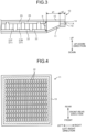
- FIG. 14 is a cross-sectional view schematically illustrating a thermoelectric power generation unit according to a second embodiment.
- a thermoelectric power generation unit 1 includes a thermoelectric power generation module 10, a heat receiving plate 2 that is a high-temperature plate, a cooling plate 3 that is a low-temperature plate, a first heat transfer member 4, and a second heat transfer member 5.
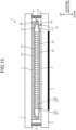
- FIG. 15 is a cross-sectional view schematically illustrating the thermoelectric power generation module according to the second embodiment.
- FIG. 16 is a partially enlarged view of a joint part of the thermoelectric power generation module in FIG. 15 .
- a plan view schematically illustrating a first base material of the thermoelectric power generation module according to the second embodiment is the same as FIG. 4 of the first embodiment.
- the second base material 12 has a peripheral edge part bent toward the first base material 11, in other words, bent so as to approach the first base material 11.
- the distal end part 12a of the second base material 12 is sandwiched by the distal end part 11a, the bent part 11b, and the distal end part 11c of the first base material 11.
- a part where the distal end part 11a, the bent part 11b, and the distal end part 11c of the first base material 11 and the distal end part 1 of the second base material 12 are joined is referred to as a joint part A.
- the distal end part 11a of the first base material 11, the distal end part 12a of the second base material 12, and the distal end part 11c of the first base material 11 are joined in an overlapping state from below in the up-down direction.
- the distal end part 11a of the first base material 11, the distal end part 12a of the second base material 12, and the distal end part 11c of the first base material 11 are joined with a resin adhesive.
- a part where the first base material 11 and the second base material 12 are joined is referred to as a joint part A.
- the joint part A is disposed in a frame shape surrounding a periphery of a plurality of pn element pairs aligned in the plane direction as viewed in the up-down direction.
- the joint part A is disposed in the peripheral edge parts of the first base material 11 and the second base material 12. In the first base material 11 and the second base material 12 having rectangular shapes, four sides are the joint parts A.
- the joint part A is separated from the cooling plate 3 and is located on the heat receiving plate 2 side.
- the joint part A which is the peripheral edge part of these materials is bonded with a resin adhesive.
- the first base material 11 and the second base material 12 are sealed at the joint part A which is the peripheral edge part.
- thermoelectric power generation module 10 by joining the first base material 11 and the second base material 12 in a state where at least one of them is bent, a joined area and a thickness of the joint part A are increased as compared with the joint part A in a state where the first base material 11 and the second base material 12 are joined without being bent.
- a sealing frame of a different kind of material since a sealing frame of a different kind of material is not used, thermal deformation, warpage, and the like due to a difference in thermal expansion coefficient are less likely to occur, and durability can be easily maintained. According to the embodiment, it is possible to reduce a possibility of deterioration of a sealing property and a possibility of disconnection of the thermoelectric power generation module 10.
- the joint part A that is a sealed part of an outer peripheral part of the thermoelectric power generation module 10 has a smaller thickness in the up-down direction, and a gap is generated between the joint part A and the cooling plate 3.
- the joint part A can be disposed away from the cooling plate 3. Therefore, in the embodiment, heat leakage from the heat receiving plate 2 to the cooling plate 3 can be suppressed at the joint part A. According to the embodiment, a possibility of reduction in power generation output of the thermoelectric power generation module 10 can be reduced.
- the first base material 11 and the second base material 12 can be bonded with a resin adhesive without using a sealing member such as a sealing material and a frame member made of an adhesive or a resin material.
- a sealing member such as a sealing material and a frame member made of an adhesive or a resin material.
- the sealing property can be maintained for a long period of time under an environment exposed to wind and rain, a high humidity and high temperature environment, and dust.
- heat resistance and temperature resistance cyclicity can be improved.
- thermoelectric power generation can be performed while insulation is maintained for a long period of time under a high-temperature environment. In this way, according to the embodiment, it is possible to suppress the occurrence of a failure due to intrusion of moisture and to stably generate power.
- thermoelectric power generation module 10 when the thermoelectric power generation module 10 is manufactured by integral reflow molding, flux tends to remain. According to the embodiment, since steam is easily removed by the remaining flux, bulging of an electrode surface can be suppressed.
- a joined area and a thickness of the joint part A can be increased as compared with a state in which the first base material 11 and the second base material 12 are joined without being bent.
- a thickness of the joint part A due to the thickness of the joint part A, warpage can be suppressed even in a case of a one-side heater.
- FIG. 17 is a partially enlarged view of a joint part of a thermoelectric power generation module according to Modification 1 of the second embodiment. Modification 1 is different from the second embodiment in a configuration of a joint part A.
- the joint part A is separated from a heat receiving plate 2 and located on a cooling plate 3 side.
- a first base material 11 has a peripheral edge part bent toward a second base material 12, in other words, bent so as to approach the second base material 12.
- a distal end part 11a of the first base material 11 is sandwiched by a distal end part 12a, a bent part 12b, and a distal end part 12c of the second base material 12.
- a peripheral edge part of the second base material 12 is folded back at the bent part 12b.
- the distal end part 12a and the distal end part 12c of the second base material 12 are separated in the up-down direction.
- the distal end part 11a of the first base material 11 is sandwiched between the distal end part 12a and the distal end part 12c of the second base material 12.
- the distal end part 11a of the first base material 11 is sandwiched by the distal end part 21a, the bent part 21b, and the distal end part 21c of the second base material 21.
- a part where the distal end part 12a, the bent part 12b, and the distal end part 12c of the second base material 12 and the distal end part 11a of the first base material 11 are joined is referred to as a joint part A.
- the distal end part 12c of the second base material 12, the distal end part 11a of the first base material 11, and the distal end part 12a of the second base material 12 are joined in an overlapping state from below in the up-down direction.
- the distal end part 12a of the second base material 12, the distal end part 11a of the first base material 11, and the distal end part 12c of the second base material 12 are bonded with a resin adhesive.
- the joint part A is disposed in the peripheral edge parts of the first base material 11 and the second base material 12.
- the joint parts A In the first base material 11 and the second base material 12 having rectangular shapes, four sides are the joint parts A.
- a dimension of a peripheral edge part of the thermoelectric power generation module 10, specifically, dimensions of the joint part A and a peripheral part thereof may be as follows.
- a length from an outer edge part of a plurality of first electrodes 22 and a plurality of second electrodes 23 disposed between the first base material 11 and the second base material 12 to the joint part A is defined as a1.
- a length of the joint part A is defined as a2.
- a length between the upper surface side of the first base material 11 and the lower surface side of the second base material 12 is defined as b.
- a1, a2, and b may be set such that a1+a2>b holds.
- the joint part A can be disposed away from the heat receiving plate 2.
- heat leakage from the heat receiving plate 2 to the cooling plate 3 can be suppressed at the joint part A.
- a1, a2, and b are set such that a1+a2>b holds, where a1 is the length from the outer edge part of the first electrodes 22 and the second electrodes 23 to the joint part A, a2 is the length of the joint part A, and b is the length between the upper surface side of the first base material 11 and the lower surface side of the second base material 12. According to the modification, it is possible to prevent the joint part A from lowering by its own weight and coming into contact with the first base material 11.
- FIG. 18 is a partially enlarged view of a joint part of a thermoelectric power generation module according to Modification 1 of the second embodiment. Modification 2 is different from the second embodiment in a configuration of a joint part A.
- the joint part A is separated from a heat receiving plate 2 and a cooling plate 3.
- the joint part A is located at an intermediate part between the heat receiving plate 2 and the cooling plate 3 in the up-down direction (thickness direction).
- a first base material 11 has a peripheral edge part bent toward a second base material 12, in other words, bent so as to approach the second base material 12.
- a distal end part 11a of the first base material 11 is sandwiched by a distal end part 12a, a bent part 12b, and a distal end part 12c of the second base material 12.
- the second base material 12 has a peripheral edge part bent toward the first base material 11, in other words, bent so as to approach the first base material 11.
- the peripheral edge part of the first base material 11 and the peripheral edge part of the second base material 12 are formed so as to approach each other.
- a peripheral edge part of the second base material 12 is folded back at the bent part 12b.
- the distal end part 12a and the distal end part 12c of the second base material 12 are separated in the up-down direction.
- the distal end part 11a of the first base material 11 is sandwiched between the distal end part 12a and the distal end part 12c of the second base material 12.
- the distal end part 11a of the first base material 11 is sandwiched by the distal end part 21a, the bent part 21b, and the distal end part 21c of the second base material 21.
- a part where the distal end part 12a, the bent part 12b, and the distal end part 12c of the second base material 12 and the distal end part 11a of the first base material 11 are joined is referred to as a joint part A.
- the distal end part 12c of the second base material 12, the distal end part 11a of the first base material 11, and the distal end part 12a of the second base material 12 are joined in an overlapping state from below in the up-down direction.
- the distal end part 12a of the second base material 12, the distal end part 11a of the first base material 11, and the distal end part 12c of the second base material 12 are bonded with a resin adhesive.
- the joint part A is disposed in the peripheral edge parts of the first base material 11 and the second base material 12.
- the joint parts A In the first base material 11 and the second base material 12 having rectangular shapes, four sides are the joint parts A.
- a length from an outer edge part of a plurality of first electrodes 22 and a plurality of second electrodes 23 disposed between the first base material 11 and the second base material 12 to the joint part A is defined as a1.
- a length of the joint part A is defined as a2.
- a length between the upper surface side of the first base material 11 and the lower surface side of the second base material 12 is defined as b.
- a1, a2, and b may be set such that a1+a2>b holds.
- the joint part A can be disposed away from the heat receiving plate 2 and the cooling plate 3.
- heat leakage from the heat receiving plate 2 to the cooling plate 3 can be suppressed at the joint part A.
- a1, a2, and b are set such that a1+a2>b holds, where a1 is the length from the outer edge part of the first electrodes 22 and the second electrodes 23 to the joint part A, a2 is the length of the joint part A, and b is the length between the upper surface side of the first base material 11 and the lower surface side of the second base material 12. According to the modification, it is possible to prevent the joint part A from lowering by its own weight and coming into contact with the first base material 11.
- FIG. 19 is a partially enlarged view of a joint part of a thermoelectric power generation module according to Modification 3 of the second embodiment. Modification 3 is different from the second embodiment in a configuration of a joint part A.
- a peripheral edge part of the first base material 11 is folded back at a bent part 11b.
- a distal end part 11a and a distal end part 11c of the first base material 11 are separated in the up-down direction.
- the distal end part 11c of the first base material 11 is joined to a distal end part 12c of a second base material 12.
- a peripheral edge part of the second base material 12 is folded back at the bent part 12b.
- the distal end part 12a and the distal end part 12c of the second base material 12 are separated in the up-down direction.
- the distal end part 12c of the second base material 12 is joined to the distal end part 11c of the first base material 11.
- the distal end part 11a of the first base material 11, the distal end part 11c of the first base material 11, the distal end part 12c of the second base material 12, and the distal end part 12a of the second base material 12 are aligned from below in the up-down direction.
- the distal end part 11c of the first base material 11 and the distal end part 12c of the second base material 12 are joined with a resin adhesive.
- a joined area and a thickness of the joint part A can be increased as compared with a state in which the first base material 11 and the second base material 12 are joined without being bent.
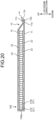
- FIG. 20 is a cross-sectional view schematically illustrating a thermoelectric power generation module according to Modification 4 of the second embodiment. Modification 4 is different from the second embodiment in a configuration of a joint part A.
- the first base material 11 and the second base material 12 are configured by bending one sheet-shaped base material 10S.
- a lower side of a bent part 10Sa is assumed to be the first base material 11, and an upper side is assumed to be the second base material 12.
- the joint part A is disposed at a peripheral edge part of the base material 10S excluding the bent part 10Sa.
- three sides make the joint part A, and one side makes the bent part 10Sa.
- an area of the joint part A can be reduced.
- a sealing property can be improved.
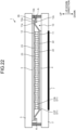
- FIG. 21 is a cross-sectional view schematically illustrating a thermoelectric power generation unit according to Modification 5 of the second embodiment.
- Modification 5 is different from the second embodiment in that a support member 2S is provided.
- a thermoelectric power generation module 10 is configured similarly to the second embodiment.
- a joint part A is separated from a cooling plate 3 and is located on a heat receiving plate 2 side.
- the support member 2S is disposed on an upper surface of the heat receiving plate 2.
- the support member 2S supports the joint part A on the heat receiving plate 2.
- the support member 2S may support the joint part A by putting the joint part A inside a slit provided in the support member 2S, or may support the joint part A by bonding the joint part A to the support member 2S with an adhesive.
- a method of supporting the joint part A by the support member 2S is not limited.
- the joint part A can be disposed away from the cooling plate 3.
- heat leakage from the heat receiving plate 2 to the cooling plate 3 can be suppressed at the joint part A.
- FIG. 22 is a cross-sectional view schematically illustrating a thermoelectric power generation unit according to Modification 6 of the second embodiment.
- Modification 6 is different from Modification 1 of the second embodiment in that a support member 3S is provided.
- a thermoelectric power generation module 10 is configured similarly to Modification 2.
- a joint part A is separated from a heat receiving plate 2 and is located on a cooling plate 3 side.
- the support member 3S is disposed on a lower surface of the cooling plate 3.
- the support member 3S supports the joint part A on the cooling plate 3.
- the support member 3S may support the joint part A by putting the joint part A inside a slit provided in the support member 3S, or may support the joint part A by bonding the joint part A to the support member 3S with an adhesive.
- a method of supporting the joint part A by the support member 3S is not limited.
- the joint part A it is possible to prevent the joint part A from lowering by its own weight.
- a position of the joint part A in the up-down direction can be supported.
- FIG. 23 is a cross-sectional view schematically illustrating a thermoelectric power generation unit according to Modification 7 of the second embodiment.
- Modification 7 is different from Modification 2 of the second embodiment in that a support member 2S and a support member 3S are provided.
- a thermoelectric power generation module 10 is configured similarly to Modification 2.
- a joint part A is located between a heat receiving plate 2 and a cooling plate 3 and is separated from the heat receiving plate 2 and the cooling plate 3.
- the support member 2S is disposed on an upper surface of the heat receiving plate 2.
- the support member 3S is disposed on a lower surface of the cooling plate 3.
- the support member 2S sandwiches and supports the joint part A in the up-down direction together with the support member 3S.
- the support member 2S and the support member 3S support the joint part A between the heat receiving plate 2 and the cooling plate 3.
- a method of supporting the joint part A by the support member 2S and the support member 3S is not limited.
- the joint part A it is possible to prevent the joint part A from lowering by its own weight.
- a position of the joint part A in the up-down direction can be supported.
- the folded shape of the first base material 11 and the second base material 12 is not limited thereto.
- the first base material 11 may be folded back in a direction away from the second base material 12.
- the second base material 12 may be folded back in a direction away from the first base material 11.
Landscapes
- Cooling Or The Like Of Semiconductors Or Solid State Devices (AREA)
Applications Claiming Priority (3)
| Application Number | Priority Date | Filing Date | Title |
|---|---|---|---|
| JP2022129049A JP2024025536A (ja) | 2022-08-12 | 2022-08-12 | 熱電発電モジュール及び熱電発電ユニット |
| JP2022129050A JP2024025537A (ja) | 2022-08-12 | 2022-08-12 | 熱電発電モジュール及び熱電発電ユニット |
| PCT/JP2023/028532 WO2024034531A1 (ja) | 2022-08-12 | 2023-08-04 | 熱電発電モジュール及び熱電発電ユニット |
Publications (1)
| Publication Number | Publication Date |
|---|---|
| EP4543183A1 true EP4543183A1 (de) | 2025-04-23 |
Family
ID=89851741
Family Applications (1)
| Application Number | Title | Priority Date | Filing Date |
|---|---|---|---|
| EP23852496.1A Withdrawn EP4543183A1 (de) | 2022-08-12 | 2023-08-04 | Modul zur thermoelektrischen erzeugung und einheit zur thermoelektrischen erzeugung |
Country Status (4)
| Country | Link |
|---|---|
| EP (1) | EP4543183A1 (de) |
| KR (1) | KR20250019146A (de) |
| CN (1) | CN119522656A (de) |
| WO (1) | WO2024034531A1 (de) |
Family Cites Families (5)
| Publication number | Priority date | Publication date | Assignee | Title |
|---|---|---|---|---|
| JPS645130U (de) | 1987-06-25 | 1989-01-12 | ||
| JP6405130B2 (ja) * | 2014-06-25 | 2018-10-17 | 株式会社Kelk | 熱電発電装置 |
| EP3444859B1 (de) * | 2016-04-15 | 2020-12-02 | Yamaha Corporation | Thermoelektrisches umwandlungsmodulpaket |
| KR101827120B1 (ko) * | 2016-05-30 | 2018-02-07 | 현대자동차주식회사 | 열전모듈용 하우징 |
| JP6866225B2 (ja) * | 2017-05-10 | 2021-04-28 | 株式会社Kelk | 熱電発電装置 |
-
2023
- 2023-08-04 EP EP23852496.1A patent/EP4543183A1/de not_active Withdrawn
- 2023-08-04 WO PCT/JP2023/028532 patent/WO2024034531A1/ja not_active Ceased
- 2023-08-04 CN CN202380053161.4A patent/CN119522656A/zh active Pending
- 2023-08-04 KR KR1020257000637A patent/KR20250019146A/ko active Pending
Also Published As
| Publication number | Publication date |
|---|---|
| CN119522656A (zh) | 2025-02-25 |
| WO2024034531A1 (ja) | 2024-02-15 |
| KR20250019146A (ko) | 2025-02-07 |
Similar Documents
| Publication | Publication Date | Title |
|---|---|---|
| CN104115294B (zh) | 热电模块、热电发电装置以及热电发电器 | |
| US7024865B2 (en) | Thermoelectric device | |
| JP5444260B2 (ja) | 熱電モジュール及び発電装置 | |
| US20060042675A1 (en) | Thermoelectric device and method of manufacturing the same | |
| EP4543183A1 (de) | Modul zur thermoelektrischen erzeugung und einheit zur thermoelektrischen erzeugung | |
| US11081633B2 (en) | Thermoelectric generation device | |
| JP2024025536A (ja) | 熱電発電モジュール及び熱電発電ユニット | |
| JP4287262B2 (ja) | 熱電変換装置 | |
| US10714670B2 (en) | Thermoelectric conversion module | |
| JP2012532468A (ja) | 複数の熱電素子を有するモジュール | |
| JP2024025537A (ja) | 熱電発電モジュール及び熱電発電ユニット | |
| TWI442853B (zh) | 在一熱製程中保護一熱敏感元件的方法及保護裝置 | |
| JP7797109B2 (ja) | 熱電発電モジュール | |
| JP3404841B2 (ja) | 熱電変換装置 | |
| KR102150308B1 (ko) | 열전발전모듈 | |
| JP2008186977A (ja) | サーモモジュールおよびその製造方法 | |
| WO2018061462A1 (ja) | 熱電変換装置 | |
| JP2011082272A (ja) | 熱電冷却装置 | |
| US10340435B2 (en) | Thermoelectric conversion device | |
| US20240429253A1 (en) | Semiconductor apparatus and electronic device | |
| US20220149260A1 (en) | Thermoelectric conversion module | |
| JP2001308397A (ja) | ペルチェモジュール | |
| CN101320781A (zh) | 热电变换装置 | |
| JP2007299780A (ja) | サーモモジュールおよびその製造方法 | |
| JP2008021931A (ja) | 熱電変換装置 |
Legal Events
| Date | Code | Title | Description |
|---|---|---|---|
| STAA | Information on the status of an ep patent application or granted ep patent |
Free format text: STATUS: THE INTERNATIONAL PUBLICATION HAS BEEN MADE |
|
| PUAI | Public reference made under article 153(3) epc to a published international application that has entered the european phase |
Free format text: ORIGINAL CODE: 0009012 |
|
| STAA | Information on the status of an ep patent application or granted ep patent |
Free format text: STATUS: REQUEST FOR EXAMINATION WAS MADE |
|
| 17P | Request for examination filed |
Effective date: 20250115 |
|
| AK | Designated contracting states |
Kind code of ref document: A1 Designated state(s): AL AT BE BG CH CY CZ DE DK EE ES FI FR GB GR HR HU IE IS IT LI LT LU LV MC ME MK MT NL NO PL PT RO RS SE SI SK SM TR |
|
| STAA | Information on the status of an ep patent application or granted ep patent |
Free format text: STATUS: THE APPLICATION HAS BEEN WITHDRAWN |
|
| 18W | Application withdrawn |
Effective date: 20250718 |