EP4545003A2 - Körperbefestigungseinheit zur kontinuierlichen blutzuckerüberwachung - Google Patents
Körperbefestigungseinheit zur kontinuierlichen blutzuckerüberwachung Download PDFInfo
- Publication number
- EP4545003A2 EP4545003A2 EP25158134.4A EP25158134A EP4545003A2 EP 4545003 A2 EP4545003 A2 EP 4545003A2 EP 25158134 A EP25158134 A EP 25158134A EP 4545003 A2 EP4545003 A2 EP 4545003A2
- Authority
- EP
- European Patent Office
- Prior art keywords
- unit
- sensor
- electric contact
- applicator
- attachable unit
- Prior art date
- Legal status (The legal status is an assumption and is not a legal conclusion. Google has not performed a legal analysis and makes no representation as to the accuracy of the status listed.)
- Pending
Links
Images












Classifications
-
- A—HUMAN NECESSITIES
- A61—MEDICAL OR VETERINARY SCIENCE; HYGIENE
- A61B—DIAGNOSIS; SURGERY; IDENTIFICATION
- A61B5/00—Measuring for diagnostic purposes; Identification of persons
- A61B5/15—Devices for taking samples of blood
- A61B5/150007—Details
- A61B5/150206—Construction or design features not otherwise provided for; manufacturing or production; packages; sterilisation of piercing element, piercing device or sampling device
-
- A—HUMAN NECESSITIES
- A61—MEDICAL OR VETERINARY SCIENCE; HYGIENE
- A61B—DIAGNOSIS; SURGERY; IDENTIFICATION
- A61B5/00—Measuring for diagnostic purposes; Identification of persons
- A61B5/0002—Remote monitoring of patients using telemetry, e.g. transmission of vital signals via a communication network
- A61B5/0015—Remote monitoring of patients using telemetry, e.g. transmission of vital signals via a communication network characterised by features of the telemetry system
- A61B5/0024—Remote monitoring of patients using telemetry, e.g. transmission of vital signals via a communication network characterised by features of the telemetry system for multiple sensor units attached to the patient, e.g. using a body or personal area network
-
- A—HUMAN NECESSITIES
- A61—MEDICAL OR VETERINARY SCIENCE; HYGIENE
- A61B—DIAGNOSIS; SURGERY; IDENTIFICATION
- A61B5/00—Measuring for diagnostic purposes; Identification of persons
- A61B5/145—Measuring characteristics of blood in vivo, e.g. gas concentration or pH-value ; Measuring characteristics of body fluids or tissues, e.g. interstitial fluid or cerebral tissue
- A61B5/14532—Measuring characteristics of blood in vivo, e.g. gas concentration or pH-value ; Measuring characteristics of body fluids or tissues, e.g. interstitial fluid or cerebral tissue for measuring glucose, e.g. by tissue impedance measurement
-
- A—HUMAN NECESSITIES
- A61—MEDICAL OR VETERINARY SCIENCE; HYGIENE
- A61B—DIAGNOSIS; SURGERY; IDENTIFICATION
- A61B5/00—Measuring for diagnostic purposes; Identification of persons
- A61B5/48—Other medical applications
- A61B5/4836—Diagnosis combined with treatment in closed-loop systems or methods
- A61B5/4839—Diagnosis combined with treatment in closed-loop systems or methods combined with drug delivery
-
- A—HUMAN NECESSITIES
- A61—MEDICAL OR VETERINARY SCIENCE; HYGIENE
- A61B—DIAGNOSIS; SURGERY; IDENTIFICATION
- A61B5/00—Measuring for diagnostic purposes; Identification of persons
- A61B5/68—Arrangements of detecting, measuring or recording means, e.g. sensors, in relation to patient
- A61B5/6846—Arrangements of detecting, measuring or recording means, e.g. sensors, in relation to patient specially adapted to be brought in contact with an internal body part, i.e. invasive
-
- A—HUMAN NECESSITIES
- A61—MEDICAL OR VETERINARY SCIENCE; HYGIENE
- A61B—DIAGNOSIS; SURGERY; IDENTIFICATION
- A61B2562/00—Details of sensors; Constructional details of sensor housings or probes; Accessories for sensors
- A61B2562/16—Details of sensor housings or probes; Details of structural supports for sensors
- A61B2562/166—Details of sensor housings or probes; Details of structural supports for sensors the sensor is mounted on a specially adapted printed circuit board
Definitions
- the present disclosure is related to a body attachable unit for continuously measuring blood glucose.
- the present disclosure is related to a body attachable unit for continuous blood glucose measurement in which, by manufacturing in a state that the body attachable unit is assembled in an applicator, the body attachable unit can be attached to a human body by simply operating the applicator by minimizing additional work, specially, by including a wireless communication chip in the body attachable unit in order to provide telecommunication with an external terminal, it is possible that the use can be more simple and convenient without additional work for connecting a separate transmitter and the maintenance can also be more easily performed, and by initiating the operation according to the manipulation of the user after the body attachable unit is attached to the human body, the operation start time can be adjusted to a proper time depending on the need of the user, the operation can be started in a stable status and more precise blood glucose measurement can be provided.
- Diabetes is a chronic medical condition that is common in modern people, and in the Republic of Korea, there are 2 million diabetes patients, about 5% of the total population.
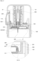
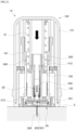
- An interlock hook (310) is formed at the plunger body (300) to interlock with the shooting plate (150) as illustrated in FIGS. 12 and 13 , the hanging protrusion part (153) interlockable with the interlock hook (310) of the plunger body (300) is formed at one side of the shooting plate (150), and the hanging protrusion part (153) may be configured to be released from the state interlocking with the interlock hook (310) as the shooting plate (150) is slidingly moved.
- the shooting plate (150) when the user operates to pressurize the pressure button (110), the shooting plate (150) is slidingly moved, and this may result in releasing the interlocked state of the plunger body (300) and the shooting plate (150) and the plunger body (300) is outwardly discharged from the first location to the second location as shown in FIGS. 15 and 16 .
- a stopper protrusion (320) may be formed at the plunger body (300) to limit a range movable to the second location, and as the plunger body (300) is moved to the second location, the stopper protrusion (320) can limit the movement of the plunger body (300) by a way of being interlocked with one side of the inner case (102). Accordingly, the plunger body (300) can be moved up to the second location by the stopper protrusion (320), and the plunger body (300) cannot be outwardly discharged from the main case (100) over that range.
- the plunger body (300) is interlocked with the stopper protrusion (320) in a state that the plunger body (300) is moved to the second location and a stopper fixing unit (1021) may be formed to limit the movement of the stopper protrusion (320).
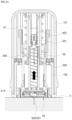
- a sensor receiving unit (301) is formed at one end portion of the plunger body (300) so that the body attachable unit (20) is insertedly received, and the body attachable unit (20) is insertedly received by the sensor receiving unit (301) and linearly move together with the plunger body (300) from the first location to the second location. As the plunger body (300) and the body attachable unit (20) are linearly moved to the second location, the sensor probe (512) and the needle unit (550) of the body attachable unit (20) are inserted into the human body.
- a sensor fixing hook (330) fixedly coupling the body attachable unit (20) by being interlockedly coupled with the body attachable unit (20) inserted to the sensor receiving unit (301) is installed at an edge of the sensor receiving unit (301).
- An interlock coupling groove (5112) is formed at both end portions of the body attachable unit (20) to be interlocked with the sensor fixing hook (330) in a state that the body attachable unit (20) is inserted into the sensor receiving unit (301).
- the sensor fixing hook (330) is coupled elastically rotatable around a rotary axis (331), in a state that the plunger body (300) is positioned at the first location as shown in FIG. 15 the sensor fixing hook (33) is elastically supported and pressurized in an inward direction so that the sensor fixing hook (330) is interlockedly coupled with the interlock coupling groove (5112) of the body attachable unit (20), and in a state that the plunger body (300) is positioned at the second location as illustrated in FIG. 16 the sensor fixing hook (330) is configured to be released from the interlock with the interlock coupling groove (5112) of the body attachable unit (20) in the operation of separating the applicator (10) from the body attachable unit (20).
- the operation of releasing the sensor fixing hook (330) from the interlock with the body attachable unit (20) can be performed in a way that the rotary shaft (331) twistingly and elastically rotates.
- a hook guide unit (not shown) is formed on the inner surface of the inner case (102) and the hook guide unit pressurizes the sensor fixing hook (330) in an inward direction to be interlocked with the body attachable unit (20) and has a cross-sectional shape having a structure that the sensor fixing hook (330) is released from the pressurization in the state of the plunger body (300) moved to the second location.
- the hook guide unit may have a structure with convex and concave surfaces on the inner surface of the inner case (102), the convex surface applies pressure to the sensor fixing hook (330) and the concave surface releases the sensor fixing hook (330) from the pressure application, and the concave is formed to release the sensor fixing hook (330) from the pressure application in a state that the sensor fixing hook (330) is moved together with the plunger body (300) to the second location.
- the embodiment of the present disclosure is manufactured in a state that the body attachable unit (20) is inserted in the applicator (10), the reuse of the body attachable unit (20) by inserting again another body attachable unit (20) to the applicator (10) may be prevented as described above.
- the main case (100) includes return prevention means for preventing the plunger body (300) returning to the first location after the plunger body (300) is moved to the second location.
- the return prevention means may be configured to comprise a interlocking body (340) formed on one side of the plunger body (300), and a return prevention hook (161) formed at the inner case (102) and configured to prevent the returning movement of the plunger body (300) by being interlockedly coupled with the interlocking body (340) of the plunger body (300) when the downward movement of the plunger body (300) from the fist location to the second location is completed.
- the return prevention hook (161) is configured to be interlocked with the interlocking body (340) by elastic restoring force in the operation of be interlocked with the interlocking body (340).
- the return prevention hook (161) may be configured to have a structure comprising a rotatable body (1611) elastically rotatably coupled around a rotary shaft (1613) and at one side of the inner case (102), and a hook body (1612) slantly protruding from the inner side surface of the rotatable body (1611) in a downward and inward direction.
- the rotary axis (1613) is configured to elastically support the rotatable body (1611) in a inward and protruding direction of the hook body (1612) by applying elastic force according to a material character of elastic material.
- the state of the operation of the return prevention hook (161) will be described in detail, and if the plunger body (300) is moved to the second location by the operation of the pressure button (110) in a state that the plunger body (300) is positioned at the first location as shown in FIG. 17 , the hook body (1612) is pressurized by the interlocking body (340) of the plunger body (200) during the movement of the plunger body (300) to the second location as illustrated in FIG. 18 , and then the return prevention hook (161) is elastically rotated in a clockwise direction (an outward direction) around the rotary axis (1613). After that, if the movement of the plunger body (300) to the second location is completed as shown in FIG.
- the return prevention hook (161) is returned by being elastically rotated around the rotary shaft (1613) in a count-clockwise direction (an inward direction). Likewise, as the return prevention hook (161) is elastically return-rotated, the lower portion of the return prevention hook (161) is interlocked with the upper portion of the interlocking body (340) of the plunger body (300), and therefore the returning movement of the plunger body (300) to the first location in a state interlocking with the return prevention hook (161) and the interlocking body (340) is prevented.
- the applicator (10) is configured to extract and remove the needle unit (550) of the body attachable unit (20) from the human body at a time of the completion of outward discharge movement of the body attachable unit (20) from the first location to the second location
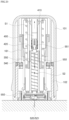
- the applicator (10) may comprise a needle extracting means (N) configured to upwardly move the needle unit (550) and extract and remove the needle unit (550) from the human body at a time of the completion of the movement of the plunger body (300) from the first location to the second location.
- the needle extracting means (N) may comprise a needle extracting body (400) coupled with the needle head (551) of the needle unit (550) and linearly move along the inner case (102) from the first location to the second location together with the plunger body (300) by being interlocked with the plunger body (300), and a needle extracting elastic spring (S2) applying elastic force to the needle extracting body (400) in a direction that the needle extracting body (400) upwardly moves toward the first location.
- a needle extracting body (400) coupled with the needle head (551) of the needle unit (550) and linearly move along the inner case (102) from the first location to the second location together with the plunger body (300) by being interlocked with the plunger body (300), and a needle extracting elastic spring (S2) applying elastic force to the needle extracting body (400) in a direction that the needle extracting body (400) upwardly moves toward the first location.
- the needle extracting body (400) is interlockedly coupled to the plunger body (300), and for this purpose, a separate elastic hook (410) configured to be elastically transformable is provided at the needle discharge body (400), and the elastic hook (410) is elastically biased in a direction interlockedly coupled to the hook interlocking unit (350) of the plunger body (300). Accordingly, if the plunger body (300) is linearly moved from the first location to the second location according to the operation of the pressure button (110), the needle extracting body (400) is also linearly moved to the second location together with the plunger body (300).
- a needle extracting pressurizing unit (130) configured to pressurize the elastic hook (410) in an inward direction so that the elastic hook (410) is released from the interlock with the hook interlocking unit (350) of the plunger body (300) according to the movement of the needle extracting body (400) to the second location is included in the inner case (102).
- the needle extracting body (400) linearly moves from the first location to the second location together with the plunger body (300) as illustrated in FIG. 19 , at the same time the elastic hook (410) of the needle extracting body (400) is pressurized by the needle extracting pressurizing unit (130) and is released from the state interlocked with the hook interlocking unit (350), and therefore the needle extracting body (400) is upwardly return-moved toward the first location by the elastic force of the needle extracting elastic spring (S2) as shown in FIG. 20 .
- the needle extracting body (400) is coupled with the needle head (551) of the needle unit (550) through an end of a needle head coupling unit (420), during the operation that the needle extracting body (400) is upwardly return-moved, the needle unit (550) is moved together and removed from the human body.
- the needle head coupling unit (420) is formed at the lower end portion of the needle extracting body (400) by a form of being interlockedly coupled to the coupling groove (552) formed at the needle head (551).
- the sensor probe (521) and the needle unit (550) of the body attachable unit (20) is inserted into the human body, but the needle unit (550) may be slightly retracted in a direction opposite to a human body insertion direction by reaction force generated by insertion resistance during the process of inserting the needle unit (550) to the human body.
- the sensor probe (521) is not inserted into the human body to a proper depth, the retraction of the needle unit (550) needs to be prevented.
- a needle supporting block may be coupled to the needle attachable body (400), and the needle supporting block is configured to downwardly support an upper end of the needle unit (550) so that the needle unit (550) cannot be upwardly moved with respect to the needle extracting body (400).
- FIGS. 21 to 25 are views illustrating use states of a continuous blood glucose measurement apparatus according to operation order step by step according to an embodiment of the present disclosure.
- the protection cap (200) of the applicator (10) is separated.
- the release paper (561) of the adhesive tape (560) of the body attachable unit (20) is separated together with the protection cap (200) and removed from the adhesive tape (560).
- the sensor applicator assembly is located on a position of the human body to attach the body attachable unit (20), and in this state, after changing a mode of the pressure button (110) from the safe mode to the pressurization standby mode, the pressure button (110) is operated to be pressurized.
- the state interlocking with the plunger body (300) is released by the movement of the shooting plate (150), therefore the plunger body (300) is downwardly moved in a direction outwardly discharged by the plunger elastic spring (S1) as illustrated in FIGS. 22 and 23 , and in this process, the needle unit (550) and the sensor probe (521) of the body attachable unit (20) is inserted into the human body (E). In this time, the body attachable unit (20) is adhered to a surface of the human body (E) by the bottom surface of the adhesive tape (560).
- the sensor fixing hook (330) of the sensor receiving unit (301) can be received from a state interlockedly coupled with the body attachable unit (20) as illustrated in FIG. 23 . Additionally, the elastic hook (410) of the needle extracting body (400) is pressurized in an inward direction by the needle extracting pressurizing unit (130) of the inner case (102) and the state interlocked with the plunger body (300) is released.
- the needle extracting body (400) is upwardly return-moved by the needle extracting elastic spring (S2) as illustrated in FIG. 24 .
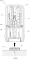
- the needle unit (550) is extracted and removed from the human body (E).
- the applicator (10) can be upwardly separated and removed as shown in FIG. 25 , and if the applicator (10) is separated and removed in this way, only the body attachable unit remains in the state attached to the human body (E).
- the sensor unit (520) and the wireless communication chip (540) of the body attachable unit (20) can initiate operation by the operation of a pressurizing operation module (570) of the body attachable unit (20) and so on, and therefore the measurement result of the blood glucose by the body attachable unit (20) can be transmitted to a separate external terminal.
- a pressurizing operation module (570) of the body attachable unit (20) can be transmitted to a separate external terminal.
- the wireless communication chip (540) are installed to the body attachable unit (20), no additional work for connecting and coupling a separate transmitter is needed.
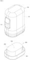
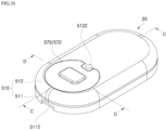
- FIG. 26 is a perspective view conceptually illustrating an outer structure of a body attachable unit attached to a human body according to an embodiment of the present disclosure
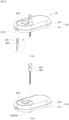
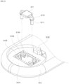
- FIG. 27 is an exploded perspective view conceptually illustrating components of a body attachable unit
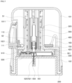
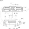
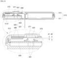
- FIG. 28 is a cross-sectional view taken along line "C-C" of FIG. 26
- FIG. 29 is a cross-sectional view taken along line "D-D” of FIG. 26
- FIG. 30 is a conceptual view illustrating a operation state of a pressurizing operation module according to an embodiment of the present disclosure.
- the body attachable unit (20) is configured to comprise the housing (510) to which the adhesive tape (560) is attached so that a bottom side of the housing (510) can be attached to skin, the sensor unit (520) disposed inside the housing (510) so that one end portion of the sensor unit (520) externally protrudes from the bottom side of the housing (10) and is inserted into the human body when the housing (510) is attached to the skin, and a PCB board (530) arranged inside the housing 510).
- One end portion of the sensor unit (520) is formed to be inserted into the human body and the other end portion of the sensor unit (520) is formed to contact the PCT board (530), a sensor body unit (522) is formed at the other end of the sensor unit (520) to be contacted with an electrical contact point of the PCB board (530), and a sensor probe unit (521) is formed at the one end portion and the sensor probe unit (521) is formed to extend in the form of being bent from one side of the sensor body unit (522) and outwardly protrudes from the housing (510) and is inserted into the human body.
- the sensor body unit (522) is formed to have a structure with a relatively large area, and the sensor probe unit (521) is formed to have a relatively narrow and long structure.
- the housing (510) may be formed to be divided into a upper housing (512) and a lower housing (511) to form an inner accommodating space, a sensor supporting unit (5121) supporting the sensor body unit (522) to be spaced apart from the electrical contact point (531) of the PCB board (530) at a certain distance is formed inside the housing (510), and a sensor guide unit (not shown) configured to support and guide a certain section of the sensor probe unit (521) is also formed inside the housing (510). Additionally, a board supporting unit (5113) for fixedly supporting the PCT board (530) at a certain location may be also formed inside the housing (510).
- the electrical contact point (531) is formed at the PCB board (530) to be electrically connected with the sensor unit (520), and the wireless communication chip (540) is installed to the PCB board (530) to transmit the glucose measurement result measured by the sensor unit (520) to an external terminal.
- the wireless communication chip (540) is installed at the inside of the body attachable unit (20) to transmit the glucose measurement result measured by the sensor unit (520) to an external terminal.
- a battery (535) configured to supply power to the PCB board (530) is installed at the inside of the housing (510), and the battery (535) is not installed at one side of the PCB board (530) but disposed at an area independent from the PCB board (530). Accordingly, the PCB board (530) and the battery (535) are independently arranged so that any area of the PCB board (530) and the battery (535) projecting into the bottom surface of the housing (530) cannot overlap each other. By arranging the PCB board (530) and the battery (535) to areas independent to each other, respectively, the thickness of the body attachable unit (20) may be reduced and the size of the body attachable unit (20) may be more minimized.
- a separate contact terminal (532) may be formed to extend to the battery (535) to be electrically contacted and connected to the battery (535).
- the body attachable unit (20) is formed so that the other end portion of the sensor unit (520), i.e., the sensor body unit (522), is contacted to the electrical contact point (531) of the PCB board (530) by the manipulation or operation of the user, and according to this electrical contact, the operation of the body attachable unit (20) may be initiated.
- the embodiment of the present embodiment is configured to perform the power supply as well as the initiation of the operation of the sensor unit (520), the wireless communication chip (540) and other components by the electrical connection of the sensor unit (520) and the PCB board (530) by the manipulation of the user.
- the housing (510) may have a separate pressurizing operation module (570) activated by the operation of the user to connect the other end portion of the sensor unit (520) and the electrical contact point (531) of the PCB board (530) by the operation of the user.
- a separate pressurizing operation module (570) activated by the operation of the user to connect the other end portion of the sensor unit (520) and the electrical contact point (531) of the PCB board (530) by the operation of the user.
- the pressurizing operation module (570) is movably connected to the housing (510) and may comprise a movable pressurizing body (571) configured to be movable in a pressurizing direction by the pressure applied by the user, and according to the movement of the movable pressurizing body (571) at least a partial area of the other end portion of the sensor unit (520) is transformed by the pressure of the movable pressurizing body (571) and contacted to the electrical contact point (531) of the PCB board (530).
- a movable pressurizing body (571) configured to be movable in a pressurizing direction by the pressure applied by the user, and according to the movement of the movable pressurizing body (571) at least a partial area of the other end portion of the sensor unit (520) is transformed by the pressure of the movable pressurizing body (571) and contacted to the electrical contact point (531) of the PCB board (530).
- the pressurizing operation module (570) may further comprises a button cover (572) having flexible material and a structure covering an outer surface of the movable pressurizing body (571) and coupled to the housing (510) so that the button cover (572) can be exposed to the outside of the body attachable unit (20) in order to be capable of the pressurizing operation by the user, and the coupling portion between the button cover (572) and the housing (510) may be processed to be sealed.
- a button cover (572) having flexible material and a structure covering an outer surface of the movable pressurizing body (571) and coupled to the housing (510) so that the button cover (572) can be exposed to the outside of the body attachable unit (20) in order to be capable of the pressurizing operation by the user, and the coupling portion between the button cover (572) and the housing (510) may be processed to be sealed.
- the seal processing means at the coupling portion between the button cover (572) and the housing (510) may be configured to use a double-side tape (580).
- a double-side tape (580) For example, one side of the double-side tape (580) is adhered to the other portion of the sensor unit (520), such as one side of the sensor body unit (522), along its circumferential edge, the other side of the double-side tape (580) is adhered to the inner-side surface of the button cover (572) along its circumferential edge, and this double-side tape (580) can seal the circumferential edge of the button cover (572).
- the double-side tape (580) may be adhered to the other side of the sensor body unit (522) along the circumferential edge as well, and by this, the sensor body unit (522) may be adhered and fixed to the sensor supporting unit (5121) along the circumferential edge of the sensor body unit (522) by using the double-side tape (580).
- the center section of the sensor body unit (522) is transformed by the pressure of the movable pressurizing body (571) and may contact the electrical contact point of the PCB board (530) as illustrated in FIG. 30 .
- the movable pressurizing body (571) is moved in the pressurized direction, because the button cover (572) is made of flexible material and the circumferential edge portion of the button cover (572) is adhered to the housing (510) by the double-side tape (580), only the center portion of the button cover (572) is transformed in the pressurized direction and the circumferential edge portion of the button cover (572) is adheredly fixed and remains the sealed state.
- the contact status can be stably maintained for stable measurement of blood glucose, and for this, the movable pressurizing body (571) is formed to be fixedly positioned in a state that the movable pressurizing body (571) is moved in a pressurized direction by the urging force.
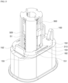
- a protruding guide unit (5711) protruding along a movement direction of the movable pressurizing body (571) is formed at the movable pressurizing body (571) as illustrated in FIG. 31 , and a locking hook (5712) may be formed at the outer circumferential surface of the protruding guide (5711).
- an interlocking projection (5124) to which the locking hook (5712) of the protruding guide unit (5711) in a state that the movable pressurizing body (571) is moved in the pressurized direction may be formed at the housing (510).
- the position of the movable pressurizing body (571) may be fixed as the locking hook (5712) is interlockedly coupled to the interlocking projection (5124) as shown in FIG. 30 .
- the interlocking projection (5124) may be formed at the sensor supporting unit (5121) of the housing (510), at least two guide fixing units (5123) separated to each other, formed along a circumferential direction and having a structure covering the protruding guide unit (5711) of the movable pressurizing body (571) are formed at the sensor supporting unit (5121) of the housing (510) as illustrated in FIG. 31 , and the interlocking protrusion (5124) may be formed at each guide fixing unit (5123). Additionally, each guide fixing unit (5123) may be arranged in a structure being elastically supported by the elastic supporting unit (5125) which is configured to be elastically transformable.
- the guide fixing unit (5123) is elastically transformed and makes the movement of the movable pressurizing body (571) smooth
- the guide fixing unit (5123) is elastically returned and the locking hook (5712) is interlockedly coupled to the interlocking projection (5124), and because the guide fixing unit (5123) is elastically supported by the elastic supporting unit (5125), the interlocking coupling state between the locking hook (5712) and the interlocking projection (5124) is stably maintained.
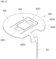
- the sensor unit (520) may consist of the sensor body unit (522) and the sensor probe unit (521) as described above, and a pressure transforming unit (523) configured to be transformed by the pressurizing movement of the movable pressurizing body (571) and contacted to the electric contact point (531) of the PCB board (530) may be formed at the sensor body unit (522).
- the pressure transforming unit (523) comprise a first cut area (5231) having a structure cut along a first cut line (5232) formed at the center section of the sensor body unit (522) as illustrated in FIG. 32 , and the first cut area (5231) may be formed to be transformable by the pressure applied by the movable pressurizing body (571).
- the pressure transforming unit (523) further comprise a second cut section (5233) positioned at the center section of the sensor body unit (522) and having a structure cut along a second cut line (5234) formed at the outer section of the first cut line (5232), and the first cut area (5231) and the second cut area (5233) may be formed to be transformable by the pressure applied by the movable pressurizing body (571).
- the first cut line (5232) is formed as an partially opened structure in a closed loop
- the second cut line (5234) is formed to have an opened section at the position opposing to the opened section of the first cut line (5232) and formed in a closed-loop structure surrounding the opened section of the first cut line (5232).
- a first cut section (5231) of the pressure transforming unit (523) is downwardly elastically transformed as illustrated in FIGS. 33 (a) and (b)
- a second cut section (5233) formed at an outer section of the first cut are (5231) is downwardly elastically transformed sequentially, and therefore because the first cut section (5231) directly contacting the electric contact point (531) of the PCB board (530) contact the electric contact point (531) of the PCB board (530) in a relatively horizontal state, the contacting state to the electric contact point (531) of the sensor body unit (522) can be more stably maintained.
- a plurality of electric contact points (531) electrically contacting the sensor body unit (522) may protrude toward the sensor body unit (522), and the protruding height of at least one of the plurality of electric contact points (531) may be higher than the rest.
- the protruding height of one of the electric contact points (531) is formed be higher than the other of the electric contact points (531), and therefore clearance distances d1, d2 are formed differently from each other.
- the sensor body unit (522) of the senor unit (520) and the electric contact point (531) of the PCB board are disposed to be separated from each other, but can contact each other by the pressure operation of the user.
- the housing (531) may be formed in a very thin structure, it may be difficult of stably maintaining the separation state between the sensor body unit (522) and the electric contact point (531) in the housing (510).
- the sensor body unit (522) and the electric contact point (531) may be manufactured and distributed to customers in a state that the sensor body unit (522) and the electric contact point (531) contact each other by the manufacture and assembly tolerance and other reasons before the pressure operation of the user.
- the protruding height of at least one of the plurality of electric contact points (531) is higher that the rest of the electric contact points (531) as described above, only the electric contact point (531) having the highest protruding height may contact the sensor body unit (522) and the other electric contact points (531) may maintain a separation state from the sensor body nit (522). This is because the highest protruding contact point (531) can perform the function of upwardly supporting the sensor body unit (522).
- the plurality of electric contact points (531) may be configured to elastically transformable and be formed to elastically protruding from the PCB board (530), and such an elastic force may perform the desired function of support and contact associated with the sensor body unit (522).
- the operation of the body attachable unit (20) is not initiated. Accordingly, the operation of the sensor unit (520), the wireless communication chip (540), and other components is not initiated, and the power supply by the battery (535) may not be initiated.
- This operation initiation prevention function can result from simple means for setting the circuit pattern of the PCB board (530) to be activated only when all of the plurality of the electric contact points (531) contact the sensor body unit (522).
- the pressurizing operation module (570) may need to be formed so that the movement distance of the movable pressurizing body (571) can be greater than the separation distance between the lowest protruding electric contact point (531) among the plurality of the electric contact points (531) and the sensor body unit (522).
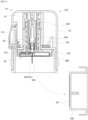
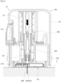
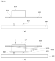
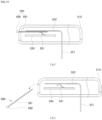
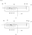
- a contact point connection module (590) which is operated by the manipulation of the user so that the sensor body unit (522) and the electric contact point (531) of the PCB board (530) contact each other is illustrated in FIGS 35 to 37 , and this contact point connection module (590) may be configured to operate in a type that in a state that the contact point connection module (590) is positioned between the sensor body unit (522) and the electric contact point (531) of the PCB board (530) to block their contact the contact point connection module (590) may be moved by the operation of the user to release from blocking the contact between the sensor body unit (522) and the electric contact point (531) of the PCB board (530).
- the movable plate (591) As shown in FIG. 35(a) , in the assembled state that the movable plate (591) is inserted into the inside of the housing (510), the movable plate (591) is positioned between the sensor body unit (522) and the electric contact point (531) to block the contact between the sensor body unit (522) and the electric contact point (531), and as illustrated in FIG. 35(b) , if the movable plate (591) is moved in a direction of being extracted and removed from the housing (510) by the operation of the user, the electric contact point (531) is upwardly moved by the elastic force and contacted to the sensor body unit (522).
- the movable plate (591) is installed to be movable from the first location to the second location by the operation of the user, and a penetrating hole (593) may be formed at one side of the movable plate (591) and the penetrating hole (593) is configured to pressurize the electric contact point (531) toward the PCB board (530) at the first location and release the pressurized state of the electric contact point (531) at the second location.
- a stopper unit (592) formed to limit a movable range of the movable plate (591) to between the first location and the second location may be formed at the movable plate (591).
- the movable plate (591) may be configured to be unable to return to the first location again so that the position of the movable plate (591) is fixed in a state that it is moved to the second location.
- a locking hook (594) is formed at one end portion of the movable plate (591), an interlocking projection (595) configured to be interlocked with the locking hook (594) in a state that the movable plate (591) is moved to the second location is formed in the housing (510), and as the locking hook (594) is interlockedly coupled to the interlocking projection (595), the position of the movable plate (591) is fixed to the second location.
- a contact point connection unit (596) made of conductive material may be additionally installed to the movable plate (591). This may be configured in a structure that the contact point connection unit (596) is installed to a portion where the penetrating hole (593) of the movable plate (591) is formed, and the electric contact point (531) and the sensor body unit (522) are electrically connected and contacted to each other by the contact point connection unit (596) when the movable plate (591) is moved.
Landscapes
- Health & Medical Sciences (AREA)
- Life Sciences & Earth Sciences (AREA)
- Engineering & Computer Science (AREA)
- Physics & Mathematics (AREA)
- Surgery (AREA)
- Public Health (AREA)
- Pathology (AREA)
- Veterinary Medicine (AREA)
- Biomedical Technology (AREA)
- Heart & Thoracic Surgery (AREA)
- Medical Informatics (AREA)
- Molecular Biology (AREA)
- Biophysics (AREA)
- Animal Behavior & Ethology (AREA)
- General Health & Medical Sciences (AREA)
- Emergency Medicine (AREA)
- Optics & Photonics (AREA)
- Computer Networks & Wireless Communication (AREA)
- Manufacturing & Machinery (AREA)
- Hematology (AREA)
- Chemical & Material Sciences (AREA)
- Bioinformatics & Cheminformatics (AREA)
- Medicinal Chemistry (AREA)
- Pharmacology & Pharmacy (AREA)
- Measurement Of The Respiration, Hearing Ability, Form, And Blood Characteristics Of Living Organisms (AREA)
Applications Claiming Priority (4)
| Application Number | Priority Date | Filing Date | Title |
|---|---|---|---|
| KR1020180089337A KR102222044B1 (ko) | 2018-07-31 | 2018-07-31 | 연속 혈당 측정용 신체 부착 유닛 |
| EP19844101.6A EP3831297B1 (de) | 2018-07-31 | 2019-06-21 | Einheit zur befestigung am körper für die kontinuierliche blutzuckerüberwachung |
| EP22196078.4A EP4137048B1 (de) | 2018-07-31 | 2019-06-21 | Körperbefestigungseinheit zur kontinuierlichen blutzuckerüberwachung |
| PCT/KR2019/007486 WO2020027434A1 (ko) | 2018-07-31 | 2019-06-21 | 연속 혈당 측정용 신체 부착 유닛 |
Related Parent Applications (3)
| Application Number | Title | Priority Date | Filing Date |
|---|---|---|---|
| EP19844101.6A Division EP3831297B1 (de) | 2018-07-31 | 2019-06-21 | Einheit zur befestigung am körper für die kontinuierliche blutzuckerüberwachung |
| EP22196078.4A Division EP4137048B1 (de) | 2018-07-31 | 2019-06-21 | Körperbefestigungseinheit zur kontinuierlichen blutzuckerüberwachung |
| EP22196078.4A Division-Into EP4137048B1 (de) | 2018-07-31 | 2019-06-21 | Körperbefestigungseinheit zur kontinuierlichen blutzuckerüberwachung |
Publications (2)
| Publication Number | Publication Date |
|---|---|
| EP4545003A2 true EP4545003A2 (de) | 2025-04-30 |
| EP4545003A3 EP4545003A3 (de) | 2025-06-25 |
Family
ID=69231978
Family Applications (3)
| Application Number | Title | Priority Date | Filing Date |
|---|---|---|---|
| EP19844101.6A Active EP3831297B1 (de) | 2018-07-31 | 2019-06-21 | Einheit zur befestigung am körper für die kontinuierliche blutzuckerüberwachung |
| EP22196078.4A Active EP4137048B1 (de) | 2018-07-31 | 2019-06-21 | Körperbefestigungseinheit zur kontinuierlichen blutzuckerüberwachung |
| EP25158134.4A Pending EP4545003A3 (de) | 2018-07-31 | 2019-06-21 | Körperbefestigungseinheit zur kontinuierlichen blutzuckerüberwachung |
Family Applications Before (2)
| Application Number | Title | Priority Date | Filing Date |
|---|---|---|---|
| EP19844101.6A Active EP3831297B1 (de) | 2018-07-31 | 2019-06-21 | Einheit zur befestigung am körper für die kontinuierliche blutzuckerüberwachung |
| EP22196078.4A Active EP4137048B1 (de) | 2018-07-31 | 2019-06-21 | Körperbefestigungseinheit zur kontinuierlichen blutzuckerüberwachung |
Country Status (6)
| Country | Link |
|---|---|
| US (2) | US12402814B2 (de) |
| EP (3) | EP3831297B1 (de) |
| JP (2) | JP7132422B2 (de) |
| KR (1) | KR102222044B1 (de) |
| AU (1) | AU2019313138B2 (de) |
| WO (1) | WO2020027434A1 (de) |
Families Citing this family (7)
| Publication number | Priority date | Publication date | Assignee | Title |
|---|---|---|---|---|
| KR102368154B1 (ko) * | 2020-03-31 | 2022-03-02 | 주식회사 아이센스 | 연속 혈당 측정 장치 |
| KR102879782B1 (ko) * | 2022-05-23 | 2025-11-03 | 주식회사 유엑스엔 | 삽입기 분리시 전원 개시되는 연속식 분석물 측정기 |
| WO2023229337A1 (ko) * | 2022-05-23 | 2023-11-30 | 주식회사 유엑스엔 | 구동부에 연동되는 스위치 활성화부를 포함하는 연속식 분석물 측정기 |
| KR102879783B1 (ko) * | 2022-05-23 | 2025-11-03 | 주식회사 유엑스엔 | 구동부에 연동되는 스위치 활성화부를 포함하는 연속식 분석물 측정기 |
| KR102813820B1 (ko) | 2022-05-23 | 2025-05-29 | 주식회사 유엑스엔 | 자기력으로 스위치부가 온오프되는 연속식 분석물 측정기 |
| KR102835131B1 (ko) * | 2022-08-05 | 2025-07-17 | 주식회사 유엑스엔 | 전원 개시 스위치부를 구비한 연속식 분석물 측정기 |
| US12171551B2 (en) | 2022-11-16 | 2024-12-24 | Laxmi Therapeutic Devices, Inc. | Applicators for glucose monitors, methods for applying glucose monitors, and glucose monitors for use with such applicators |
Family Cites Families (13)
| Publication number | Priority date | Publication date | Assignee | Title |
|---|---|---|---|---|
| US6579690B1 (en) | 1997-12-05 | 2003-06-17 | Therasense, Inc. | Blood analyte monitoring through subcutaneous measurement |
| US20040010207A1 (en) * | 2002-07-15 | 2004-01-15 | Flaherty J. Christopher | Self-contained, automatic transcutaneous physiologic sensing system |
| US7381184B2 (en) * | 2002-11-05 | 2008-06-03 | Abbott Diabetes Care Inc. | Sensor inserter assembly |
| EP3524142B1 (de) * | 2004-07-13 | 2021-04-28 | Dexcom, Inc. | Transkutaner analytsensor |
| US20090076360A1 (en) * | 2007-09-13 | 2009-03-19 | Dexcom, Inc. | Transcutaneous analyte sensor |
| US9402544B2 (en) * | 2009-02-03 | 2016-08-02 | Abbott Diabetes Care Inc. | Analyte sensor and apparatus for insertion of the sensor |
| KR101145668B1 (ko) | 2010-11-22 | 2012-05-24 | 전자부품연구원 | 연속 혈당 측정 시스템 |
| AU2012352560B2 (en) | 2011-12-11 | 2017-01-19 | Abbott Diabetes Care Inc. | Analyte sensor devices, connections, and methods |
| US10456064B2 (en) * | 2014-09-03 | 2019-10-29 | Nova Biomedical Corporation | Subcutaneous sensor inserter and method |
| WO2016153313A1 (en) * | 2015-03-25 | 2016-09-29 | Samsung Electronics Co., Ltd. | Wearable electronic device |
| US10765369B2 (en) * | 2016-04-08 | 2020-09-08 | Medtronic Minimed, Inc. | Analyte sensor |
| KR101773583B1 (ko) * | 2016-06-03 | 2017-09-01 | 주식회사 아이센스 | 연속 혈당 측정기용 어플리케이터 |
| WO2018222009A1 (ko) | 2017-06-02 | 2018-12-06 | 주식회사 아이센스 | 연속 혈당 측정기용 센서 어플리케이터 조립체 |
-
2018
- 2018-07-31 KR KR1020180089337A patent/KR102222044B1/ko active Active
-
2019
- 2019-06-21 WO PCT/KR2019/007486 patent/WO2020027434A1/ko not_active Ceased
- 2019-06-21 JP JP2021503123A patent/JP7132422B2/ja active Active
- 2019-06-21 EP EP19844101.6A patent/EP3831297B1/de active Active
- 2019-06-21 US US17/261,530 patent/US12402814B2/en active Active
- 2019-06-21 EP EP22196078.4A patent/EP4137048B1/de active Active
- 2019-06-21 EP EP25158134.4A patent/EP4545003A3/de active Pending
- 2019-06-21 AU AU2019313138A patent/AU2019313138B2/en active Active
-
2022
- 2022-08-25 JP JP2022134454A patent/JP7467547B2/ja active Active
-
2024
- 2024-10-23 US US18/924,661 patent/US20250040838A1/en active Pending
Also Published As
| Publication number | Publication date |
|---|---|
| JP2021531871A (ja) | 2021-11-25 |
| EP4545003A3 (de) | 2025-06-25 |
| JP2022162114A (ja) | 2022-10-21 |
| KR20200014000A (ko) | 2020-02-10 |
| EP3831297B1 (de) | 2022-11-16 |
| AU2019313138B2 (en) | 2022-06-16 |
| EP4137048A1 (de) | 2023-02-22 |
| EP3831297A4 (de) | 2021-09-15 |
| EP4137048B1 (de) | 2025-05-07 |
| EP3831297A1 (de) | 2021-06-09 |
| NZ772734A (en) | 2023-08-25 |
| US12402814B2 (en) | 2025-09-02 |
| US20210290117A1 (en) | 2021-09-23 |
| KR102222044B1 (ko) | 2021-03-04 |
| US20250040838A1 (en) | 2025-02-06 |
| WO2020027434A1 (ko) | 2020-02-06 |
| JP7132422B2 (ja) | 2022-09-06 |
| JP7467547B2 (ja) | 2024-04-15 |
| AU2019313138A1 (en) | 2021-03-04 |
Similar Documents
| Publication | Publication Date | Title |
|---|---|---|
| EP4397238A2 (de) | Vorrichtung zur kontinuierlichen blutzuckermessung | |
| AU2019316453B2 (en) | Body attachment unit for continuous glucose monitoring | |
| US20240122504A1 (en) | Continuous blood glucose measurement apparatus | |
| US20250040838A1 (en) | Body attachable unit for continuous blood glucose measurement | |
| US20250090053A1 (en) | Body attachable unit for continuous blood glucose measurement | |
| US20240389897A1 (en) | Continuous blood glucose measurement apparatus | |
| NZ772734B2 (en) | Body attachment unit for continuous blood glucose monitoring |
Legal Events
| Date | Code | Title | Description |
|---|---|---|---|
| PUAI | Public reference made under article 153(3) epc to a published international application that has entered the european phase |
Free format text: ORIGINAL CODE: 0009012 |
|
| STAA | Information on the status of an ep patent application or granted ep patent |
Free format text: STATUS: REQUEST FOR EXAMINATION WAS MADE |
|
| 17P | Request for examination filed |
Effective date: 20250314 |
|
| AC | Divisional application: reference to earlier application |
Ref document number: 3831297 Country of ref document: EP Kind code of ref document: P Ref document number: 4137048 Country of ref document: EP Kind code of ref document: P |
|
| AK | Designated contracting states |
Kind code of ref document: A2 Designated state(s): AL AT BE BG CH CY CZ DE DK EE ES FI FR GB GR HR HU IE IS IT LI LT LU LV MC MK MT NL NO PL PT RO RS SE SI SK SM TR |
|
| REG | Reference to a national code |
Ref country code: DE Ref legal event code: R079 Free format text: PREVIOUS MAIN CLASS: A61B0005145000 Ipc: A61B0005150000 |
|
| PUAL | Search report despatched |
Free format text: ORIGINAL CODE: 0009013 |
|
| AK | Designated contracting states |
Kind code of ref document: A3 Designated state(s): AL AT BE BG CH CY CZ DE DK EE ES FI FR GB GR HR HU IE IS IT LI LT LU LV MC MK MT NL NO PL PT RO RS SE SI SK SM TR |
|
| RIC1 | Information provided on ipc code assigned before grant |
Ipc: A61B 5/145 20060101ALI20250519BHEP Ipc: A61B 5/1486 20060101ALI20250519BHEP Ipc: A61B 5/15 20060101AFI20250519BHEP |
|
| GRAP | Despatch of communication of intention to grant a patent |
Free format text: ORIGINAL CODE: EPIDOSNIGR1 |
|
| STAA | Information on the status of an ep patent application or granted ep patent |
Free format text: STATUS: GRANT OF PATENT IS INTENDED |