EP4545049A2 - Herzklappenprothesen - Google Patents
Herzklappenprothesen Download PDFInfo
- Publication number
- EP4545049A2 EP4545049A2 EP25162582.8A EP25162582A EP4545049A2 EP 4545049 A2 EP4545049 A2 EP 4545049A2 EP 25162582 A EP25162582 A EP 25162582A EP 4545049 A2 EP4545049 A2 EP 4545049A2
- Authority
- EP
- European Patent Office
- Prior art keywords
- valve
- support
- prosthesis
- radially
- heart
- Prior art date
- Legal status (The legal status is an assumption and is not a legal conclusion. Google has not performed a legal analysis and makes no representation as to the accuracy of the status listed.)
- Pending
Links
Images


Classifications
-
- A—HUMAN NECESSITIES
- A61—MEDICAL OR VETERINARY SCIENCE; HYGIENE
- A61F—FILTERS IMPLANTABLE INTO BLOOD VESSELS; PROSTHESES; DEVICES PROVIDING PATENCY TO, OR PREVENTING COLLAPSING OF, TUBULAR STRUCTURES OF THE BODY, e.g. STENTS; ORTHOPAEDIC, NURSING OR CONTRACEPTIVE DEVICES; FOMENTATION; TREATMENT OR PROTECTION OF EYES OR EARS; BANDAGES, DRESSINGS OR ABSORBENT PADS; FIRST-AID KITS
- A61F2/00—Filters implantable into blood vessels; Prostheses, i.e. artificial substitutes or replacements for parts of the body; Appliances for connecting them with the body; Devices providing patency to, or preventing collapsing of, tubular structures of the body, e.g. stents
- A61F2/02—Prostheses implantable into the body
- A61F2/24—Heart valves ; Vascular valves, e.g. venous valves; Heart implants, e.g. passive devices for improving the function of the native valve or the heart muscle; Transmyocardial revascularisation [TMR] devices; Valves implantable in the body
- A61F2/2412—Heart valves ; Vascular valves, e.g. venous valves; Heart implants, e.g. passive devices for improving the function of the native valve or the heart muscle; Transmyocardial revascularisation [TMR] devices; Valves implantable in the body with soft flexible valve members, e.g. tissue valves shaped like natural valves
-
- A—HUMAN NECESSITIES
- A61—MEDICAL OR VETERINARY SCIENCE; HYGIENE
- A61F—FILTERS IMPLANTABLE INTO BLOOD VESSELS; PROSTHESES; DEVICES PROVIDING PATENCY TO, OR PREVENTING COLLAPSING OF, TUBULAR STRUCTURES OF THE BODY, e.g. STENTS; ORTHOPAEDIC, NURSING OR CONTRACEPTIVE DEVICES; FOMENTATION; TREATMENT OR PROTECTION OF EYES OR EARS; BANDAGES, DRESSINGS OR ABSORBENT PADS; FIRST-AID KITS
- A61F2/00—Filters implantable into blood vessels; Prostheses, i.e. artificial substitutes or replacements for parts of the body; Appliances for connecting them with the body; Devices providing patency to, or preventing collapsing of, tubular structures of the body, e.g. stents
- A61F2/02—Prostheses implantable into the body
- A61F2/24—Heart valves ; Vascular valves, e.g. venous valves; Heart implants, e.g. passive devices for improving the function of the native valve or the heart muscle; Transmyocardial revascularisation [TMR] devices; Valves implantable in the body
- A61F2/2403—Heart valves ; Vascular valves, e.g. venous valves; Heart implants, e.g. passive devices for improving the function of the native valve or the heart muscle; Transmyocardial revascularisation [TMR] devices; Valves implantable in the body with pivoting rigid closure members
-
- A—HUMAN NECESSITIES
- A61—MEDICAL OR VETERINARY SCIENCE; HYGIENE
- A61F—FILTERS IMPLANTABLE INTO BLOOD VESSELS; PROSTHESES; DEVICES PROVIDING PATENCY TO, OR PREVENTING COLLAPSING OF, TUBULAR STRUCTURES OF THE BODY, e.g. STENTS; ORTHOPAEDIC, NURSING OR CONTRACEPTIVE DEVICES; FOMENTATION; TREATMENT OR PROTECTION OF EYES OR EARS; BANDAGES, DRESSINGS OR ABSORBENT PADS; FIRST-AID KITS
- A61F2/00—Filters implantable into blood vessels; Prostheses, i.e. artificial substitutes or replacements for parts of the body; Appliances for connecting them with the body; Devices providing patency to, or preventing collapsing of, tubular structures of the body, e.g. stents
- A61F2/02—Prostheses implantable into the body
- A61F2/24—Heart valves ; Vascular valves, e.g. venous valves; Heart implants, e.g. passive devices for improving the function of the native valve or the heart muscle; Transmyocardial revascularisation [TMR] devices; Valves implantable in the body
- A61F2/2409—Support rings therefor, e.g. for connecting valves to tissue
-
- A—HUMAN NECESSITIES
- A61—MEDICAL OR VETERINARY SCIENCE; HYGIENE
- A61F—FILTERS IMPLANTABLE INTO BLOOD VESSELS; PROSTHESES; DEVICES PROVIDING PATENCY TO, OR PREVENTING COLLAPSING OF, TUBULAR STRUCTURES OF THE BODY, e.g. STENTS; ORTHOPAEDIC, NURSING OR CONTRACEPTIVE DEVICES; FOMENTATION; TREATMENT OR PROTECTION OF EYES OR EARS; BANDAGES, DRESSINGS OR ABSORBENT PADS; FIRST-AID KITS
- A61F2/00—Filters implantable into blood vessels; Prostheses, i.e. artificial substitutes or replacements for parts of the body; Appliances for connecting them with the body; Devices providing patency to, or preventing collapsing of, tubular structures of the body, e.g. stents
- A61F2/02—Prostheses implantable into the body
- A61F2/24—Heart valves ; Vascular valves, e.g. venous valves; Heart implants, e.g. passive devices for improving the function of the native valve or the heart muscle; Transmyocardial revascularisation [TMR] devices; Valves implantable in the body
- A61F2/2412—Heart valves ; Vascular valves, e.g. venous valves; Heart implants, e.g. passive devices for improving the function of the native valve or the heart muscle; Transmyocardial revascularisation [TMR] devices; Valves implantable in the body with soft flexible valve members, e.g. tissue valves shaped like natural valves
- A61F2/2418—Scaffolds therefor, e.g. support stents
-
- A—HUMAN NECESSITIES
- A61—MEDICAL OR VETERINARY SCIENCE; HYGIENE
- A61F—FILTERS IMPLANTABLE INTO BLOOD VESSELS; PROSTHESES; DEVICES PROVIDING PATENCY TO, OR PREVENTING COLLAPSING OF, TUBULAR STRUCTURES OF THE BODY, e.g. STENTS; ORTHOPAEDIC, NURSING OR CONTRACEPTIVE DEVICES; FOMENTATION; TREATMENT OR PROTECTION OF EYES OR EARS; BANDAGES, DRESSINGS OR ABSORBENT PADS; FIRST-AID KITS
- A61F2230/00—Geometry of prostheses classified in groups A61F2/00 - A61F2/26 or A61F2/82 or A61F9/00 or A61F11/00 or subgroups thereof
- A61F2230/0002—Two-dimensional shapes, e.g. cross-sections
- A61F2230/0004—Rounded shapes, e.g. with rounded corners
- A61F2230/001—Figure-8-shaped, e.g. hourglass-shaped
-
- A—HUMAN NECESSITIES
- A61—MEDICAL OR VETERINARY SCIENCE; HYGIENE
- A61F—FILTERS IMPLANTABLE INTO BLOOD VESSELS; PROSTHESES; DEVICES PROVIDING PATENCY TO, OR PREVENTING COLLAPSING OF, TUBULAR STRUCTURES OF THE BODY, e.g. STENTS; ORTHOPAEDIC, NURSING OR CONTRACEPTIVE DEVICES; FOMENTATION; TREATMENT OR PROTECTION OF EYES OR EARS; BANDAGES, DRESSINGS OR ABSORBENT PADS; FIRST-AID KITS
- A61F2230/00—Geometry of prostheses classified in groups A61F2/00 - A61F2/26 or A61F2/82 or A61F9/00 or A61F11/00 or subgroups thereof
- A61F2230/0002—Two-dimensional shapes, e.g. cross-sections
- A61F2230/0028—Shapes in the form of latin or greek characters
- A61F2230/005—Rosette-shaped, e.g. star-shaped
-
- A—HUMAN NECESSITIES
- A61—MEDICAL OR VETERINARY SCIENCE; HYGIENE
- A61F—FILTERS IMPLANTABLE INTO BLOOD VESSELS; PROSTHESES; DEVICES PROVIDING PATENCY TO, OR PREVENTING COLLAPSING OF, TUBULAR STRUCTURES OF THE BODY, e.g. STENTS; ORTHOPAEDIC, NURSING OR CONTRACEPTIVE DEVICES; FOMENTATION; TREATMENT OR PROTECTION OF EYES OR EARS; BANDAGES, DRESSINGS OR ABSORBENT PADS; FIRST-AID KITS
- A61F2230/00—Geometry of prostheses classified in groups A61F2/00 - A61F2/26 or A61F2/82 or A61F9/00 or A61F11/00 or subgroups thereof
- A61F2230/0063—Three-dimensional shapes
- A61F2230/0069—Three-dimensional shapes cylindrical
Definitions
- the present technology relates generally to heart valve prostheses and associated methods.
- several embodiments are directed to transcatheter heart valve devices for percutaneous replacement of native heart valves, such as a mitral valve.
- the human heart is a four chambered, muscular organ that provides blood circulation through the body during a cardiac cycle.
- the four main chambers include the right atria and right ventricle which supplies the pulmonary circulation, and the left atria and left ventricle which supplies oxygenated blood received from the lungs to the remaining body.
- atrioventricular valves tricuspid and mitral valves
- semi-lunar valves pulmonary valve and aortic valve
- These valves contain leaflets that open and shut in response to blood pressure changes caused by the contraction and relaxation of the heart chambers. The leaflets move apart from each other to open and allow blood to flow downstream of the valve, and coapt to close and prevent backflow or regurgitation in an upstream manner.
- Diseases associated with heart valves can include stenosis and valvular insufficiency or regurgitation.
- valvular stenosis causes the valve to become narrowed and hardened which can prevent blood flow to a downstream heart chamber to occur at the proper flow rate and cause the heart to work harder to pump the blood through the diseased valve.
- Valvular insufficiency or regurgitation occurs when the valve does not close completely, allowing blood to flow backwards, thereby causing the heart to be less efficient.
- a diseased or damaged valve which can be congenital, age-related, drug-induced, or in some instances, caused by infection, can result in an enlarged, thickened heart that loses elasticity and efficiency.
- Heart valve diseases can include weakness, shortness of breath, dizziness, fainting, palpitations, anemia and edema, and blood clots which can increase the likelihood of stroke or pulmonary embolism. Symptoms can often be severe enough to be debilitating and/or life threatening.
- Prosthetic heart valves have been developed for repair and replacement of diseased and/or damaged heart valves. Such valves can be percutaneously delivered and deployed at the site of the diseased heart valve through catheter-based systems. Such prosthetic heart valves can be delivered while in a low-profile or compressed/contracted arrangement so that the prosthetic valves can be contained within a sheath component of a delivery catheter and advanced through the patient's vasculature. Once positioned at the treatment site, the prosthetic valves can be expanded to engage tissue at the diseased heart valve region to, for instance, hold the prosthetic valve in position.
- the mitral valve presents numerous challenges, such as prosthetic valve dislodgement or improper placement due to the presence of chordae tendinae and remnant leaflets, leading to valve impingement. Additional challenges can include providing a prosthetic valve that resists pre-mature failure of various components that can occur when subjected to the distorting forces imparted by the native anatomy and during the cardiac cycle.
- anatomical challenges associated with treatment of a mitral valve include providing a prosthetic valve to accommodate the oval or kidney shape.
- the kidney-shaped mitral valve annulus has muscle only along the exterior wall of the valve with only a thin vessel wall that separates the mitral valve and the aortic valve. This anatomical muscle distribution, along with the high pressures experienced on the left ventricular contraction, can be problematic for mitral valve prosthesis.
- Embodiments hereof are directed to heart valve prostheses and methods of percutaneous implantation thereof.
- the heart valve prostheses have a compressed configuration for delivery via a vasculature or other body lumens to a native heart valve of a patient and an expanded configuration for deployment within the native heart valve.
- the heart valve prosthesis may include a frame having a valve support that is configured to hold a prosthetic valve component therein, and a plurality of support arms extending from the valve support such that when the heart valve prosthesis is in the expanded configuration the plurality of support arms are configured to extend toward the first end of the valve support for engaging a subannular surface of the native heart valve.
- One or more of the plurality of support arms comprises a curvilinear-shaped support arm, the curvilinear-shaped support arm being formed to have opposing first and second arcuate regions longitudinally separated by a straight region extending therebetween, with the first arcuate region being formed to curve toward the valve support proximate a downstream portion thereof, the straight region being formed to slant toward the valve support while joining the first arcuate region and the second arcuate region, and the second arcuate region being formed to curve away from the valve support proximate an upstream portion thereof.
- a heart valve prosthesis for implantation at a native valve region of a heart includes a valve support having an upstream portion and a downstream portion, the valve support being configured to retain a prosthetic valve component therein and having a plurality of support arms extending from the downstream portion of the valve support.
- each support arm is configured to extend from the downstream portion toward the upstream portion and to have a curvilinear shape with a first curved region having a first radius of curvature, a second curved region having a second radius of curvature and an elongate region extending between the first curved region and the second curved region.
- the curvilinear shape is configured to absorb distorting forces exerted thereon by the native valve region.
- a heart valve prosthesis for treating a native mitral valve of a patient.
- the heart valve prosthesis includes a cylindrical support having an upstream portion, a downstream portion and a first cross-sectional dimension, wherein the cylindrical support is configured to hold a prosthetic valve component that inhibits retrograde blood flow.
- a plurality of S-shaped support arms extend from the downstream portion of the cylindrical support, such that when the heart valve prosthesis is in an expanded configuration the S-shaped support arms are configured to extend in an upstream direction to engage cardiac tissue on or below an annulus of the native mitral valve.
- a radially-extending segment extends from the upstream portion of the cylindrical support and is of a second cross-sectional dimension greater than the first cross-sectional dimension.
- the radially-extending segment is configured to engage cardiac tissue on or above the annulus of the native mitral valve such that when the heart valve prosthesis is in the expanded configuration and deployed at the native mitral valve, the annulus is positioned between upstream curved segments of the S-shaped support arms and the radially-extending segment.
- distal and proximal are used in the following description with respect to a position or direction relative to the treating clinician or with respect to a prosthetic heart valve device.
- distal are a position distant from or in a direction away from the clinician when referring to delivery procedures or along a vasculature.
- proximal and distal can refer to the location of portions of the device with respect to the direction of blood flow.
- proximal can refer to an upstream position or a position of blood inflow
- distal can refer to a downstream position or a position of blood outflow.
- Embodiments of the present technology as described herein can be combined in many ways to treat one or more of many valves of the body including valves of the heart such as the mitral valve.
- the embodiments of the present technology can be therapeutically combined with many known surgeries and procedures, for example, such embodiments can be combined with known methods of accessing the valves of the heart such as the mitral valve with antegrade or retrograde approaches, and combinations thereof.
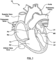
- FIG. 1 is a schematic sectional illustration of a mammalian heart 10 that depicts the four heart chambers (right atria RA, right ventricle RV, left atria LA, left ventricle LV) and native valve structures (tricuspid valve TV, mitral valve MV, pulmonary valve PV, aortic valve AV).
- FIG. 2A is a schematic sectional illustration of a left ventricle LV of a mammalian heart 10 showing anatomical structures and a native mitral valve MV. Referring to FIGS. 1 and 2A together, the heart 10 comprises the left atrium LA that receives oxygenated blood from the lungs via the pulmonary veins.
- the left atrium LA pumps the oxygenated blood through the mitral valve MV and into the left ventricle LV during ventricular diastole.
- the left ventricle LV contracts during systole and blood flows outwardly through the aortic valve AV, into the aorta and to the remainder of the body.
- the leaflets LF of the mitral valve MV meet evenly at the free edges or "coapt" to close and prevent back flow of blood during contraction of the left ventricle LV ( FIG. 2A ).
- the leaflets LF attach the surrounding heart structure via a fibrous ring of connective tissue called an annulus AN.
- the flexible leaflet tissue of the mitral leaflets LF are connected to papillary muscles PM, which extend upwardly from the lower wall of the left ventricle LV and the interventricular septum IVS, via branching tendons called chordae tendinae CT.
- leakage from the left ventricle LV into the left atrium LA will occur.
- Several structural detects can cause the mitral leaflets LF to prolapse and regurgitation to occur, including ruptured chordae tendinae CT, impairment of papillary muscles PM (e.g., due to ischemic heart disease), and enlargement of the heart and/or mitral valve annulus AN (e.g., cardiomyopathy).
- FIG. 3 is a superior view of a mitral valve MV isolated from the surrounding heart structures and further illustrating the shape and relative sizes of the leaflets LF and annulus AN.
- the mitral valve MV generally has a "D" or kidney shape.
- the mitral valve MV includes an anterior leaflet AL which meets a posterior leaflet PL at a coaptation line when closed. When the anterior leaflet AL and posterior leaflet PL fail to meet, regurgitation between the leaflets AL, PL or at commissures C at the corners between the leaflets can occur.
- Embodiments of prosthetic heart valve devices and associated methods in accordance with the present technology are described in this section with reference to FIGS. 4A-10 . It will be appreciated that specific elements, substructures, uses, advantages, and/or other aspects of the embodiments described herein and with reference to FIGS. 4A-10 can be suitably interchanged, substituted or otherwise configured with one another in accordance with additional embodiments of the present technology.
- a prosthetic heart valve device in accordance with embodiments described herein, can be implanted for replacement of a diseased or damaged native mitral valve or prior implanted prosthetic mitral valve in a patient, such as in a patient suffering from a prolapsed mitral valve illustrated in FIG. 2A .
- the device is suitable for implantation and replacement of other diseased or damaged heart valves or prior implanted prosthetic heart valves, such as tricuspid, pulmonary and aortic heart valves.
- FIG. 4A is a side view of a heart valve prosthesis or a prosthetic heart valve device 100 in a radially expanded or deployed configuration (e.g., a deployed state) in accordance with an embodiment of the present technology.
- FIG. 4B is a top view of the heart valve prosthesis 100 as configured in FIG. 4A
- FIG. 4C is a top view of the prosthesis 100 taken along lines C-C of FIG. 4A .
- the heart valve prosthesis 100 includes a frame or stent-like support structure 110 that includes a tubular portion or structural valve support 120 that defines a lumen 121 for retaining, holding and/or securing a prosthetic valve component 130 therein.
- the valve support 120 can be generally cylindrical in shape having an upstream portion 124 at a first end 125 and a downstream portion 126 at a second end 127 that are oriented along a longitudinal axis L A of the valve support 120 ( FIG. 4A ).
- the frame 110 further includes one or more support arms 140 extending radially outward from the valve support 120 and generally in an upstream direction from the downstream portion 126 of the valve support 120 (e.g., to reach behind native leaflets of the mitral valve and engage cardiac tissue in the subannular region within the left ventricle).
- At least some of the support arms 140 can have a curvilinear shape 141 configured to atraumatically engage the native annulus and substantially absorb distorting forces such that the prosthesis 100 is supported by the annulus when prosthetic valve component 130 is closed during systole.
- the frame 110 further includes a radially-extending segment or radial extension portion 150 at least partially surrounding and extending from the upstream portion 124 of the valve support 120.
- the radially-extending segment 150 can include a plurality of self-expanding struts 152 configured to radially expand when the prosthesis 100 is deployed to the expanded configuration.
- the radially-extending segment 150 can engage tissue on or above the annulus when implanted within a native mitral valve space.
- the radially-extending segment 150 can retain the valve support 120 in a desired position within the native valve region (e.g., between the native leaflets and annulus of the mitral valve).
- the radially-extending segment 150 and/or the valve support 120 can include a sealing material 160 that can extend around an upper or upstream surface 154 or a lower or downstream surface 155 ( FIG. 4A ) of the radially-extending segment 150, and/or around an interior wall 122 or an exterior wall 123 of the valve support 120 to prevent leakage of blood (e.g., paravalvular leakage) between the implanted prosthesis 100 and the native heart tissue.
- a sealing material 160 can extend around an upper or upstream surface 154 or a lower or downstream surface 155 ( FIG. 4A ) of the radially-extending segment 150, and/or around an interior wall 122 or an exterior wall 123 of the valve support 120 to prevent leakage of blood (e.g., paravalvular leakage) between the implanted prosthesis 100 and the native heart tissue.
- the radially-extending segment 150 and valve support 120 are shown having generally circular cross-sectional shapes with the radially-extending segment 150 having a cross-sectional dimension D 1 that is greater than a cross-sectional dimension D 2 of the valve support 120.
- the radially-extending segment 150, the valve support 120 or both can have other cross-sectional shapes, such as to accommodate the D-shaped or kidney-shaped mitral valve.
- the radially-extending segment 150 and/or valve support 120 may expand to an irregular, non-cylindrical, or oval-shaped configuration for accommodating the mitral valve or other valves.
- the native valves e.g., mitral, aortic
- the native valves can be uniquely sized and/or have other unique anatomical shapes and features that vary between patients, and the prosthesis 100 for replacing or repairing such valves can be suitable for adapting to the size, geometry and other anatomical features of such native valves.
- the radially-extending segment 150 can expand within the native heart valve region while simultaneously being flexible so as to conform to the region engaged by the radially-extending segment 150.
- FIGS. 4A and 4B show the radially-extending segment 150 having the plurality of struts 152 that outwardly extend from the exterior wall 123 at the first end 125 of the valve support 120.
- the struts 152 are arranged relatively evenly about a circumference of the valve support 120, and individual struts 152 join an adjacent strut 152 at a crown 156.
- the crowns 156 have an atraumatic tip 157 that prevents injury to the cardiac tissue during deployment and through the cardiac cycle. Examples of suitable radially-extending segments 150 are described in U.S. Patent Publication No. 2015/0119982 , which is incorporated herein by reference in its entirety.
- a plurality of support arms 140 extend from the downstream portion 126 of the valve support 120, and are generally evenly spaced about the circumference of the exterior wall 123 of the valve support 120 ( FIG. 4C ).
- the support arms 140 can be unevenly spaced, grouped, irregularly spaced, etc. about the circumference.
- the support arms 140 can be grouped closer together and extend from the valve support 120 at positions that generally align with the anterior and posterior leaflets of the mitral valve when deployed.
- the embodiment shown in FIG. 4C has twelve support arms 140 evenly spaced about the circumference of the valve support 120.
- the prosthesis 100 can include less than 12 support arms 140, e.g., two support arms, two to six support arms, greater than six support arms, nine support arms, etc., or more than twelve support arms 140.
- the support arms 140 may extend from the valve support 120 at or near the second end 127 and may be described as extending generally toward the upstream portion 124 along or in parallel with the exterior wall 123 of the valve support 120.
- the support arm 140 can have the generally curvilinear shape 141 or similar geometry.
- the curvilinear shape 141 includes opposing arcuate or curved regions 142, 144 longitudinally separated by a slanted elongate or straight region 143 that extends therebetween.
- arcuate region 142 of a curvilinear support arm 140 When positioned for use within a native mitral valve, arcuate region 142 of a curvilinear support arm 140 may be referred to as a downstream curved segment 142 and arcuate region 144 of the curvilinear support arm 140 may be referred to as an upstream curved segment 144.
- the curvilinear shape 141 includes a first arcuate (e.g., curved) region 142 formed to curve in a direction toward the exterior wall 123 to engage a portion of at least one leaflet of the native heart valve or other structures in the heart valve region, such as chordae tendinae.
- the first arcuate region 142 may extend around a downstream edge of the native valve leaflet.
- the support arm includes the straight region 143 configured to follow from the first arcuate region 142 and to slant in a direction toward the exterior wall 123 at an intermediate or middle portion 170 of the valve support 120.
- the support arm 140 further includes a second arcuate (e.g., curved) region 144 formed to curve in a direction away from the exterior wall 123 of the valve support 120 and to engage tissue at or proximate to the native heart valve when implanted.
- the second arcuate region 144 can engage subannular tissue and/or portions of a heart chamber wall, e.g., a ventricular wall, in an atraumatic matter.
- the first arcuate region 142 is longitudinally separated from the second arcuate region 144 by the straight or elongate region 143 to form or define a substantially S-shaped profile.
- the second arcuate region 144 on each of the support arms 140 provides or defines a contact area or landing zone 145 that is configured to atraumatically engage tissue at or near the subannular tissue so as to inhibit tissue erosion and/or resist movement of the prosthesis 100 in an upstream direction during ventricular systole, as is described further herein.
- the second arcuate region 144 includes a widened and/or flattened portion 446 that forms the landing zone 145.
- the widened portion 446 has a first width W 1 that is greater than a width W 2 at the first arcuate region 142 of the support arm 140.
- the landing zone 145 When the prosthesis 100 is deployed and in contact with tissue (e.g., subannular tissue, native leaflets, ventricle wall, etc.) via the widened portion 446, the landing zone 145 effectively distributes native tissue contact over a greater surface area to inhibit tissue erosion and to distribute load stress on the support arms 140.
- tissue e.g., subannular tissue, native leaflets, ventricle wall, etc.
- the landing zone 145 includes grooves 447 formed along the widened portion 446 that can provide additional barriers against movement of the landing zone 145 with respect to the contacted tissue.
- the landing zone 145 can include raised portions, bumps, cut-outs and other features that provide additional movement resistance against the contacted tissue once deployed.
- the support arms 140 provide atraumatic contact in a manner that limits or inhibits tissue erosion and/or abrasion following implantation of the prosthesis 100.
- the support arm 140 includes an arm tip 148 that can be rounded or otherwise atraumatic to cardiac tissue engaged by the arm tip 148 either during deployment or when fully implanted.
- the arm tip 148 includes a hole 448 for attaching the support arms 140 to a delivery catheter (not shown) in a radially-compressed configuration for delivery to a target site.
- one or more of the holes 448 may be filled with a secondary material (e.g. Tantalum, Platinum, Gold) for improved visibility during fluoroscopy-guided delivery.
- a secondary material e.g. Tantalum, Platinum, Gold
- the support arms 140 may not include a hole 448 and/or other landing zone features (e.g., grooves 447) without departing from the scope hereof.
- the frame 110 is formed from a resilient or shape memory material, such as a nickel titanium alloy (e.g., nitinol), that has a mechanical memory to return to the deployed or expanded configuration.
- a resilient or shape memory material such as a nickel titanium alloy (e.g., nitinol)
- nickel titanium alloy e.g., nitinol
- the frame 110 can be a unitary structure that defines the radially-extending segment 150 at the inflow portion of the prosthesis 100, the valve support 120 and the plurality of support arms 140, and the frame 110 so described may be made from stainless steel, a pseudo-elastic metal such as nickel titanium alloy or nitinol, or a so-called super alloy, which may have a base metal of nickel, cobalt, chromium, or other metal.
- the frame 110 can be formed as a unitary structure, for e.g., from a laser cut, fenestrated, nitinol or other metal tube.
- Mechanical memory may be imparted to the structure that forms the frame 110 by thermal treatment to achieve a spring temper in the stainless steel, for example, or to set a shape memory in a susceptible metal alloy, such as nitinol.
- the frame 110 may also include polymers or combinations of metals, polymers or other materials.
- the frame 110 can be a flexible metal frame or support structure having a plurality of ribs and/or struts (e.g., struts 128, 152) geometrically arranged to provide a latticework capable of being radially compressed (e.g., in a delivery state, not shown) for delivery to a target native valve site, and capable of radially expanding (e.g., to the radially expanded configuration shown in FIG. 4A ) for deployment and implantation at the target native valve site.
- struts 128, 152 e.g., struts 128, 152
- the ribs and struts 128 can be arranged in a plurality of geometrical patterns that can expand or flex and contract while providing sufficient resilience and strength for maintaining the integrity of the prosthetic valve component 130 housed within.
- the struts 128 can be arranged in a circumferential pattern about the longitudinal axis L A , wherein the circumferential pattern includes a series of diamond, zig-zagged, sinusoidal, or other geometric shapes.
- the frame 110 can include separately manufactured components that are coupled, linked, welded, or otherwise mechanically attached to one another to form the frame 110.
- the radially-extending segment 150 can be coupled to the upstream portion 124 of the valve support 120 (e.g., at attachments points 129a on the struts 128 as defined by a diamond-shaped geometry of the valve support 120).
- the support arms 140 can be coupled to the downstream portion 126 of the valve support 120 (e.g., at attachment points 129b on the struts 128 as defined by the diamond-shaped geometry of the valve support 120).
- Other arrangements and attachment points are contemplated for coupling one or more of the support arms 140 and radially-extending segment 150 to the valve support 120.
- the support arms 140 can be coupled to the valve support 120 via an arm post 146.
- the arm post 146 can be integral with the frame 110 such that the arm post 146 is an extension of one or more struts 128.
- the arm posts 146 and valve support 120 may be coupled by a variety of methods known in the art, e.g., soldering, welding, bonding, rivets or other fasteners, mechanical interlocking, or any combination thereof.
- valve support 120 can be a balloon-expandable tubular metal stent, and the radially-extending segment 150 and the support arms 140 of the frame 110 may be formed from material and by methods so as to be self-expanding as described above.
- support arms 140 may extend from or be coupled to an intermediate or middle portion 170 of the valve support 120 without departing from the scope hereof.
- the prosthetic valve component 130 may be coupled to the interior wall 122 of the valve support 120 for governing blood flow through the heart valve prosthesis 100.
- the prosthetic valve component 130 can include a plurality of leaflets 132 (shown individually as 132a-b) that coapt and are configured to allow blood flow through the prosthesis 100 in a downstream direction (e.g., from the first end 125 to the second end 127) and inhibit blood flow in an upstream direction (e.g., from the second end 127 to the first end 125).
- the prosthetic valve component 130 can have three leaflets 132 (tricuspid arrangement, not shown) or more than three leaflets 132 that coapt to close the prosthetic valve component 130.
- the leaflets 132 can be formed of bovine pericardium or other natural material (e.g., obtained from heart valves, aortic roots, aortic walls, aortic leaflets, pericardial tissue, such as pericardial patches, bypass grafts, blood vessels, intestinal submucosal tissue, umbilical tissue and the like from humans or animals) that are mounted to the interior wall 122 of the valve support 120.
- valve leaflets 132 include DACRON ® polyester (commercially available from Invista North America S.A.R.L. of Wilmington, DE), other cloth materials, nylon blends, polymeric materials, and vacuum deposition nitinol fabricated materials.
- valve leaflets 132 can be made of an ultrahigh molecular weight polyethylene material commercially available under the trade designation DYNEEMA from Royal DSM of the Netherlands. With certain leaflet materials, it may be desirable to coat one or both sides of the leaflet with a material that will prevent or minimize overgrowth. It can be further desirable that the leaflet material is durable and not subject to stretching, deforming, or fatigue.
- FIG. 5A is a schematic illustration showing a partial side view the prosthesis 100 implanted at a native mitral valve region of the heart 10 in accordance with an embodiment of the present technology.
- the prosthesis 100 is shown in FIG. 5A having only two support arms 140 for purposes of illustration only. It is understood that the prosthesis 100, in some arrangements, can have more than two support arms 140, e.g., greater than six support arms, etc.
- the upstream portion 124 of the valve support 120 is oriented to receive blood inflow from a first heart chamber, e.g., left atrium LA for mitral valve MV replacement, left ventricle for aortic valve replacement, etc., and the downstream portion 126 is oriented to release blood outflow into a second heart chamber or structure, e.g., left ventricle LV for mitral valve MV replacement, aorta for aortic valve replacement.
- a first heart chamber e.g., left atrium LA for mitral valve MV replacement, left ventricle for aortic valve replacement, etc.
- the downstream portion 126 is oriented to release blood outflow into a second heart chamber or structure, e.g., left ventricle LV for mitral valve MV replacement, aorta for aortic valve replacement.
- the heart valve prosthesis 100 can be intravascularly delivered to a desired native valve region of the heart 10, such as near the mitral valve MV, while in the radially compressed configuration (not shown) and within a delivery catheter (not shown).
- the prosthesis 100 can be advanced to a position within or downstream of the native mitral valve annulus AN where the support arms 140 and the downstream portion 126 of the valve support 120 are released from the delivery catheter.
- the delivery catheter can then release the upstream portion 124 of the valve support 120 and the radially-extending segment 150 at a position within or upstream of the native mitral valve MV so as to enlarge toward the radially expanded configuration and engage the native tissue within the native heart valve region.
- the prosthesis 100 can be positioned such that the radially-extending segment 150 resides within the left atrium and engages tissue at or near the supra-annular region.
- the prosthesis 100 is further positioned such that the support arms 140 engage outward-facing surfaces of the native leaflets LF to capture the leaflets between the support arms 140 and the exterior wall 123 of the valve support 120.
- the contact area or landing zone 145 of each of the support arms 140 is configured to engage tissue at or near the subannular tissue so as to resist movement of the prosthesis 100 in an upstream direction during ventricular systole, as is described further herein.
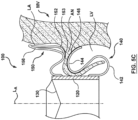
- FIG. 5B is an enlarged sectional view of the heart valve prosthesis 100 of FIG. 5A shown in a radially expanded configuration (e.g., a deployed state) and in accordance with an embodiment of the present technology.
- the prosthesis 100 is schematically shown positioned at a mitral valve MV on the right-hand side of the illustration.
- the heart valve prosthesis 100 is configured to position the prosthetic valve component 130, which is retained or held within the valve support 120, in a desired location and orientation within the native mitral valve MV. Referring to FIGS.
- the radially-extending segment 150 can be positioned to expand within the atrial space above the mitral valve and engage cardiac tissue within the atrial space.
- at least a lower surface or apex 153 of an arching or S-shaped strut 152 can provide a tissue engaging region for contacting the supra-annular tissue, for example to provide sealing against paravalvular leakage and to inhibit downstream migration of the prosthesis 100 relative to the native annulus.
- an upward oriented lip portion 158 of the struts 152 that rise to form the crowns 156 can provide further tissue contact zones that can further inhibit downstream movement of the prosthesis 100 relative to the native annulus, and inhibit rocking or side-to-side rotation of the prosthesis 100 within the native valve during the cardiac cycle, thereby inhibiting paravalvular leakage and assuring alignment of the prosthetic valve component 130 within the native annulus.
- the radially-extending segment 150 can be a flange, a brim, a ring, finger-like projections or other projection into the atrial space for at least partially engaging tissue at or above a supra-annular region thereof.
- the support arms 140 are shown having the curvilinear shape 141 and extending from the downstream portion 126 of the valve support 120.
- the support arms 140 are configured to engage both the native leaflets (if present) and/or the subannular region of the mitral valve MV within the ventricular space.
- the support arms 140 are configured to engage an outside surface (e.g., ventricle-facing side) of the leaflet such that the native leaflet is captured between the support arm 140 and the exterior wall 123 of the valve support 120.
- the preformed curvilinear shape 141 of the support arm 140 for example at a transitional apex 144a of the second arcuate region 144, can be biased toward the exterior wall 123 of the valve support 120 such that a compressive force Fc 1 presses the leaflet LF against the exterior wall 123 in a manner that pinches, grasps, crimps or otherwise confines the leaflet within the space 105 between the support arm 140 and the exterior wall 123 of the valve support 120.
- the second arcuate region 144 is configured to engage the subannular region (e.g., behind the leaflet LF) via the contact area or landing zone 145.
- the second arcuate region 144 can contact tissues below the annulus AN, such as the ventricle wall (as shown in FIG. 5C ).
- the landing zone 145 distributes surface contact over a larger region to inhibit tissue erosion and to distribute load stress on the support arms 140 in an atraumatic manner.
- the curvilinear shape 141 of the support arm 140 can form a substantially S-shaped profile.
- the support arms 140 can be more flexible (e.g., than other portions of the frame 110) and/or be made of resilient material (e.g., shape-memory material, super-elastic material, etc.) that can absorb forces exerted on the support arms 140 when implanted in the heart 10 and during the cardiac cycle. For example, these forces can cause the substantially S-shaped profile to temporarily deform, deflect or otherwise change shape.
- the curvilinear shape 141 of the support arms can provide compressive forces Fc 2 in an upstream direction (e.g., at the contact zone 145) and against annulus tissue.
- the apex 153 (e.g., lower surface) of the radially-extending segment 150 can be longitudinally separated from the landing zone 145 of the second arcuate region by a gap 106.
- the gap 106 can be sized to receive annular tissue therein.
- the apex 153 of the arching strut 152 can provide a downward compressive force Fc 3 on the contacted tissue of the annulus that opposes the compressive force F C2 across the gap 106. Accordingly, the compressive forces Fc 2 and Fc 3 may be aligned and/or opposed to each other such that annular tissue is captured between the radially-extending segment 150 and the support arms 140 having the preformed curvilinear shape 141.
- the struts 152 can be circumferentially- and radially-aligned with the second arcuate region 144 of the support arms 140 such that the compressive force Fc 1 is directly opposed to the compressive force Fc 3 (shown in FIG. 5B ) to effectively pinch the annulus AN therebetween.
- the portions of the prosthesis 100 can be provided with a sealing material 160 ( FIG. 4B ) to cover at least portions of the prosthesis 100.
- the sealing material 160 can prevent paravalvular leakage as well as provide a medium for tissue ingrowth following implantation, which can further provide biomechanical retention of the prosthesis 100 in the desired deployment location within the native heart valve region.
- the sealing material 160 or portions thereof may be a low-porosity woven fabric, such as polyester, DACRON ® polyester, or polytetrafluoroethylene (PTFE), which creates a one-way fluid passage when attached to the frame 110.
- the sealing material 160 or portions thereof may be a looser knit or woven fabric, such as a polyester or PTFE knit, which can be utilized when it is desired to provide a medium for tissue ingrowth and the ability for the fabric to stretch to conform to a curved surface.
- polyester velour fabrics may alternatively be used for at least portions of the sealing material 160, such as when it is desired to provide a medium for tissue ingrowth on one side and a smooth surface on the other side.
- These and other appropriate cardiovascular fabrics are commercially available from Bard Peripheral Vascular, Inc. of Tempe, AZ, for example.
- the sealing material 160 or portions thereof may be a natural graft material, such as pericardium or another membranous tissue.
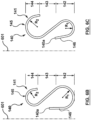
- FIGS. 6A-6C are side views of a variety of support arm configurations in accordance with additional embodiments of the present technology.
- the support arm 140 in one embodiment, can generally have the curvilinear shape 141 with first and second arcuate regions 142, 144 separated by an elongate or substantially straight region 143 that together extend substantially in parallel with a longitudinal axis 601 (e.g., generally aligned with the longitudinal axis L a of the valve support 120; FIG. 5B ).
- the support arm 140 has an S-shaped profile. As illustrated in FIGS.
- the first arcuate region 142 can have a first radius of curvature R 1 and the second arcuate region 144 can have a second radius of curvature R 2 that, in certain embodiments, is (a) substantially equal to the first radius of curvature R 1 ( FIG. 6A ), (b) substantially less than the first radius of curvature R 1 ( FIG. 6B ), or is (c) substantially greater than the first radius of curvature R 1 ( FIG. 6C ).
- the second arcuate region 144 can have the tissue engaging portion or contact zone 145 for engaging subannular or other cardiac tissue during and/or after deployment.
- the support arm 140 includes the arm post 146 at a first end 140a and from which the first arcuate region 142 generally extends in the outward direction from the longitudinal axis L A , 601 and in radial alignment with the downstream portion 126 of the valve support 120 ( FIG. 5B ).
- the first arcuate region 142 curves about a first center of curvature C C1 . As shown in FIG.
- the substantially straight or elongate portion 143 extends between the first arcuate region 142 and the second arcuate region 144.
- the second arcuate region 144 is radially aligned with an intermediate or middle portion 170 of the valve support 120 between the upstream and downstream portions 124, 126 ( FIG. 5B ).
- the second arcuate region 144 curves about a second center of curvature C C2 .
- a first axis line (not shown) drawn through the first center of curvature C C1 is parallel to a second axis line (not shown) drawn through the second center of curvature C C2 .
- the first and second axis lines are substantially perpendicular to the longitudinal axis L A , 601 ( FIG. 6A ).
- the arm post 146 can be generally linear and have a suitable length L 1 for extending the first arcuate region 142 a desirable distance downstream from a connection (not shown) to the valve support 120.
- the arm post 146 can be generally parallel to the longitudinal axis L A of the prosthesis 100 and/or valve support 120 (shown in Figure 5B ).
- a first curved segment 610 of the region 142 extends radially outward from the arm post 146.
- first curved segment 610 may be described as arcuate or generally curved in an outward and downstream direction until it reaches a transitional apex 142a of the first arcuate region 142. Thereafter a second curved segment 614 of the first arcuate region 142 continues the curve profile and extends outward and in a generally upstream direction from the transitional apex 142a.
- a first transitional point 616 initiates the elongate region 143 of the support arm 140, with the elongate region 143 slanting and extending in an upward and inward direction relative to the longitudinal axis L A of the valve support 120 to end at a second transitional point 618.
- the general curvature of the second arcuate region 144 initiates as the second transitional point 618 such that following the curvature of the second arcuate region 144, a third curved segment 620 is defined that generally curves in an outward and upstream direction to reach a transitional apex 144a of the second arcuate region 144.
- a fourth curved segment 622 of the second arcuate region 144 continues the curve profile and extends (e.g., relative to the longitudinal axis LA) from the transitional apex 144a in an outward direction and can also curve slightly downstream toward a free-end or arm tip 148.
- An opening 624 between the second arcuate region 144 and the first arcuate region 142 of the support arm 140 is generally created in the space between the third transition 618 and the first end 140a of the support arm 140, and can be configured to receive a native leaflet LF and/or chordae tendinae therein.
- Other embodiments of support arms 140 can have curved segments 610, 614, 620 and 622 with less curvature or greater curvature.
- the embodiments of support arms 140 shown in FIGS. 5B and 6A-6D can have an overall height H 1 that is less than a height H 2 of the valve support 120 ( FIGS. 5B and 6A ).
- Other arrangements and heights are also contemplated. Accordingly, in addition to the radius of curvature R 1 , R 2 of the first and second arcuate regions 142, 144 and/or other geometric features/alterations, the overall height H 1 of the support arm 140 can be selected to accommodate the anatomy at the desired target location of the heart valve.
- the first and second arcuate regions 142, 144 of the support arm 140 can be configured to absorb, translate and/or mitigate distorting forces present within the heart during, for example, systole and diastole.
- the support arms 140 have a spring-type response to distorting forces (e.g., physical forces capable of exerting on and changing a contour of the support arm 140).
- the support arms 140 can have multiple hinge points for flexing or absorbing such distorting forces.
- a first distorting force can be absorbed as a result of the spring-type response of the individual support arms 140 in a manner that elastically or reversibly and temporarily distorts the unbiased configuration of the support arm 140.
- the spring-type motion continues with the transition of the support arm contour from the distorted position back to an unbiased configuration.
- a spring-type response of the support arm 140 occurs in a manner that is counter to the first distorting force.
- the extent to which the support arm 140 is compressed and/or extended is proportional to the distorting force(s) exerted on the support arm.
- the support arm 140 can have a selected stiffness which provides a constant for the distance or delta of distortion (e.g., compression, distention).
- the support arms 140 can have constant stiffness along the entire length of the support arm and covering all of the multiple hinge points.
- the support arms 140 can have variable stiffness along the length of the support arm and encompassing the different hinge points.
- Such selectivity in the stiffness of the individual support arms 140 can provide prosthesis designs to accommodate unique and variable native structures, such as for accommodating variable distorting forces exerted by the native mitral valve region.
- Variable stiffness may be accomplished in a variety of ways: i) differences in the support arm cross-sectional area, ii) variable cold working of select support arms in the case of conventional elastic-plastic metals (e.g. stainless steel, titanium alloys, cobalt-chromium based alloys), and/or iii) selectively heating or providing a heat treatment of one or more support arms and not others.
- the shape and/or size of the first and second arcuate regions 142, 144 can be selected to accommodate forces, such as radially compressive forces, e.g., exerted by the native annulus and/or leaflets Fa, longitudinal diastolic Fd and systolic Fs forces, hoop stress, etc. Absorption of the distorting forces can serve to prevent translation of those forces to the valve support 120 and thereby preserve the coaptation of the prosthetic valve component 130. Additionally, and as further shown in FIG.
- the support arms 140 may flex, bend, rotate or twist under the distorting forces while the valve support 120 substantially maintains its rigidity and/or original shape (e.g., a generally circular shape).
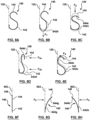
- FIGS. 8A-8H are side views of various support arms 140 flexing in response to a distorting force in accordance with further embodiments of the present technology.
- the degree of flexibility of individual support arms 140 may be consistent among all support arms 140 of a prosthesis 100, or, alternatively, some support arms 140 may be more flexible than other support arms 140 on the same prosthesis 100.
- a degree of flexibility of individual support arms 140 may be consistent throughout an entire length of the support arm 140 or curvature of the first and second arcuate regions 142, 144. In other embodiments, however, the degree of flexibility can vary along the length and/or curvature of each support arm 140.
- the first and second arcuate regions 142, 144 of the support arms 140 may flex relative to the arm post 146, the valve support 120 (shown in dotted lines) and/or be configured to alter their arcuate shape(s) in response to varying distorting forces F that can be applied by the surrounding tissue during or after implantation of the prosthesis 100.
- the first arcuate region 142 may flex downward to a shape/position 842b ( FIG. 8B ) in response to a downward force F 1 caused by, for example, chordal load (e.g., from chordal tendinae engaging the first arcuate region 142).
- the second arcuate region 144 may flex downward and the first arcuate region 142 may compress from the static position ( FIG. 8A ) to shapes/positions 844c and 842c, respectively ( FIG. 8C ), in response to a downward force F 2 caused by, for example, a tip load (e.g., from left ventricle pressure).
- the first and second arcuate regions 142, 144 may flex or compress inward to shapes/positions 842d, 844d ( FIG. 8D ) in response to laterally directed inward forces F 3a , F 3b caused by, for example, ventricle wall load (e.g., from left ventricle contraction).
- first and second arcuate regions 142, 144 may flex, rotate inwardly/outwardly and/or deform in response to the laterally directed forces F 3a , F 3b , F 4 , or downward in response to the generally vertically directed forces F 1 , F 2 .
- the first and second arcuate regions 142, 144 shown in a static position in FIG 8F may also flex and/or rotate laterally, for example, to positions 842g/844g ( FIG. 8G ) or 842h/844h ( FIG. 8H ) in response to a laterally-directed force F 5 , by bending at one or more transitions 140a, 142a, 616, 618 and 144a ( FIG. 6A ), for example, at unique and variable angles off a midline 802 such that the arm tips 148 may be splayed away from each other.
- FIG. 9 is an enlarged sectional view of the heart valve prosthesis 100 of FIGS. 5A-5B shown in a compressed delivery configuration (e.g., a low-profile or radially compressed state) configured in accordance with an embodiment of the present technology.
- the prosthesis 100 can be configured for delivery within a delivery catheter sheath (not shown) in the radially compressed configuration shown in FIG. 9 .
- the radially-extending segment 150 can be elongated, folded or otherwise arranged to longitudinally extend in a substantially straightened state from the valve support 120.
- the plurality of support arms 140 are longitudinally extended and arranged in a substantially straightened state for percutaneous delivery to the targeted native heart valve. As shown in FIG.
- the support arms 140 can extend beyond the second end 127 of the valve support 120 such that the first arcuate region 142 is generally linear and substantially parallel with the longitudinal axis L A , while the second arcuate region 144 remains in a curved profile.
- the support arms 140 can move to an outward biased position as the delivery catheter sheath (not shown) is withdrawn and the radially-extending segment 150 can self-expand to the radially expanded configuration ( FIG. 5B ).
- the radially-extending segment 150 and the valve support 120 can transition from the radially expanded configuration (e.g., the deployed state) ( FIG. 5B ) back to the radially contracted configuration ( FIG. 9 ) using a catheter device or other lateral retaining sheath.
- Access to the mitral valve or other atrioventricular valve can be accomplished through a patient's vasculature in a percutaneous manner.
- the approach to the mitral valve may be antegrade and may rely on entry into the left atrium by crossing the inter-atrial septum.
- approach to the mitral valve can be retrograde where the left ventricle is entered through the aortic valve or via a transapical puncture.
- the interventional tools and supporting catheter(s) may be advanced to the heart intravascularly and positioned adjacent the target cardiac valve in a variety of manners.
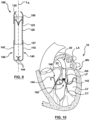
- the heart valve prosthesis 100 may be delivered to a native mitral valve region for repair or replacement of the native valve via a transseptal approach (shown in FIG. 10 ), a retrograde approach through the aortic valve, or via a transapical puncture.
- a transseptal approach shown in FIG. 10
- a retrograde approach through the aortic valve or via a transapical puncture.
- Suitable transapical and/or transatrial implantation procedures that may be adapted for use with the heart valve prostheses 100 described herein are disclosed in U.S. Appl. No. 13/572,842 filed August 13, 2012 to Igor Kovalsky , U.S. Appl. Pub. No. 2011/0208297 to Tuval et al. , and U.S. Appl. Pub. No. 2012/0035722 to Tuval et al , each of which is incorporated by reference herein in its entirety.
- FIG. 10 is a sectional view of the heart 10 illustrating a step of a method of implanting a heart valve prosthesis 100 using a transseptal approach in accordance with another embodiment of the present technology.
- the prosthesis 100 may be advanced into proximity to the mitral valve MV within a delivery catheter 20.
- a guidewire (not shown) may be used over which the delivery catheter 20 may be slidably advanced.
- the sheath 22 is then proximally retracted allowing the prosthesis 100 to expand such that the support arms 140 are in an outward position spatially separated from the longitudinal axis L A and while the valve support 120 remains radially contracted.
- the outward movement of the support arms 140 is facilitated by the shape-memory bias of the first arcuate region 142.
- the first arcuate region 142 can have a third radius of curvature R 3 that is greater than the first radius of curvature R 1 , whereas the second arcuate region 144 continues to have the second radius of curvature R 2 .
- the second arcuate region 144 provides for atraumatic engagement of cardiac tissue during all phases of deployment within the Mitral Valve MV (as shown in FIG. 10 ).
- the second arcuate region 144 is configured to deflect in response to contact with chordae tendinae CT when transitioning between the radially contracted configuration and the radially expanded configuration.
- the second arcuate region 144 can also atraumatically engage a wall of the left ventricle LV during deployment and as the support arm 140 moves or swings behind the native leaflets LF. When the support arms 140 are fully deployed (e.g., FIG.
- the support arms 140 are positioned further inwardly relative to the longitudinal axis L A and such that the leaflets LF are engaged between the support arms 140 and the valve support 120.
- the sheath 22 may be further retracted to release the valve support 120 and the radially-extending segment 150 (e.g., within the space of the left atrium LA).
- the delivery catheter 20 can still be connected to the prosthesis 100 (e.g., system eyelets, not shown, are connected to the prosthesis eyelets) so that the operator can further control the placement of the prosthesis 100 as it expands toward the radially expanded configuration.
- the prosthesis 100 may be expanded upstream or downstream of the target location then pushed downstream or upstream, respectively, into the desired target location before releasing the prosthesis 100 from delivery catheter 20.
- the delivery catheter 20 may be retracted in a proximal direction and the prosthesis 100 detached while in the radially expanded configuration at the native target valve (e.g., mitral valve MV).
- the native target valve e.g., mitral valve MV
Landscapes
- Health & Medical Sciences (AREA)
- Cardiology (AREA)
- Engineering & Computer Science (AREA)
- Biomedical Technology (AREA)
- Heart & Thoracic Surgery (AREA)
- Transplantation (AREA)
- Oral & Maxillofacial Surgery (AREA)
- Vascular Medicine (AREA)
- Life Sciences & Earth Sciences (AREA)
- Animal Behavior & Ethology (AREA)
- General Health & Medical Sciences (AREA)
- Public Health (AREA)
- Veterinary Medicine (AREA)
- Prostheses (AREA)
Applications Claiming Priority (3)
| Application Number | Priority Date | Filing Date | Title |
|---|---|---|---|
| US14/879,861 US10456243B2 (en) | 2015-10-09 | 2015-10-09 | Heart valves prostheses and methods for percutaneous heart valve replacement |
| PCT/US2016/055585 WO2017062515A1 (en) | 2015-10-09 | 2016-10-05 | Heart valves prostheses |
| EP16784348.1A EP3359090B1 (de) | 2015-10-09 | 2016-10-05 | Herzklappenprothesen |
Related Parent Applications (1)
| Application Number | Title | Priority Date | Filing Date |
|---|---|---|---|
| EP16784348.1A Division EP3359090B1 (de) | 2015-10-09 | 2016-10-05 | Herzklappenprothesen |
Publications (2)
| Publication Number | Publication Date |
|---|---|
| EP4545049A2 true EP4545049A2 (de) | 2025-04-30 |
| EP4545049A3 EP4545049A3 (de) | 2025-07-02 |
Family
ID=57153569
Family Applications (2)
| Application Number | Title | Priority Date | Filing Date |
|---|---|---|---|
| EP25162582.8A Pending EP4545049A3 (de) | 2015-10-09 | 2016-10-05 | Herzklappenprothesen |
| EP16784348.1A Active EP3359090B1 (de) | 2015-10-09 | 2016-10-05 | Herzklappenprothesen |
Family Applications After (1)
| Application Number | Title | Priority Date | Filing Date |
|---|---|---|---|
| EP16784348.1A Active EP3359090B1 (de) | 2015-10-09 | 2016-10-05 | Herzklappenprothesen |
Country Status (5)
| Country | Link |
|---|---|
| US (2) | US10456243B2 (de) |
| EP (2) | EP4545049A3 (de) |
| JP (2) | JP7019563B2 (de) |
| CN (2) | CN112690929B (de) |
| WO (1) | WO2017062515A1 (de) |
Families Citing this family (158)
| Publication number | Priority date | Publication date | Assignee | Title |
|---|---|---|---|---|
| US20090276040A1 (en) * | 2008-05-01 | 2009-11-05 | Edwards Lifesciences Corporation | Device and method for replacing mitral valve |
| US8652202B2 (en) | 2008-08-22 | 2014-02-18 | Edwards Lifesciences Corporation | Prosthetic heart valve and delivery apparatus |
| US10517719B2 (en) | 2008-12-22 | 2019-12-31 | Valtech Cardio, Ltd. | Implantation of repair devices in the heart |
| US9968452B2 (en) | 2009-05-04 | 2018-05-15 | Valtech Cardio, Ltd. | Annuloplasty ring delivery cathethers |
| US8449599B2 (en) | 2009-12-04 | 2013-05-28 | Edwards Lifesciences Corporation | Prosthetic valve for replacing mitral valve |
| US8870950B2 (en) | 2009-12-08 | 2014-10-28 | Mitral Tech Ltd. | Rotation-based anchoring of an implant |
| US9072603B2 (en) * | 2010-02-24 | 2015-07-07 | Medtronic Ventor Technologies, Ltd. | Mitral prosthesis and methods for implantation |
| US20110224785A1 (en) | 2010-03-10 | 2011-09-15 | Hacohen Gil | Prosthetic mitral valve with tissue anchors |
| US11653910B2 (en) | 2010-07-21 | 2023-05-23 | Cardiovalve Ltd. | Helical anchor implantation |
| US9763657B2 (en) | 2010-07-21 | 2017-09-19 | Mitraltech Ltd. | Techniques for percutaneous mitral valve replacement and sealing |
| EP4119095A1 (de) * | 2011-03-21 | 2023-01-18 | Cephea Valve Technologies, Inc. | Scheibenförmige ventilvorrichtung |
| EP3725269A1 (de) | 2011-06-23 | 2020-10-21 | Valtech Cardio, Ltd. | Verschlusselement zur verwendung mit einer annuloplastiestruktur |
| WO2013021374A2 (en) | 2011-08-05 | 2013-02-14 | Mitraltech Ltd. | Techniques for percutaneous mitral valve replacement and sealing |
| US8852272B2 (en) | 2011-08-05 | 2014-10-07 | Mitraltech Ltd. | Techniques for percutaneous mitral valve replacement and sealing |
| EP3417813B1 (de) | 2011-08-05 | 2020-05-13 | Cardiovalve Ltd | Perkutaner mitralklappenersatz |
| US9387075B2 (en) * | 2011-09-12 | 2016-07-12 | Highlife Sas | Transcatheter valve prosthesis |
| US9283072B2 (en) | 2012-07-25 | 2016-03-15 | W. L. Gore & Associates, Inc. | Everting transcatheter valve and methods |
| US10376360B2 (en) | 2012-07-27 | 2019-08-13 | W. L. Gore & Associates, Inc. | Multi-frame prosthetic valve apparatus and methods |
| US9232995B2 (en) | 2013-01-08 | 2016-01-12 | Medtronic, Inc. | Valve prosthesis and method for delivery |
| US10321986B2 (en) | 2012-12-19 | 2019-06-18 | W. L. Gore & Associates, Inc. | Multi-frame prosthetic heart valve |
| US9101469B2 (en) | 2012-12-19 | 2015-08-11 | W. L. Gore & Associates, Inc. | Prosthetic heart valve with leaflet shelving |
| US9968443B2 (en) | 2012-12-19 | 2018-05-15 | W. L. Gore & Associates, Inc. | Vertical coaptation zone in a planar portion of prosthetic heart valve leaflet |
| US9737398B2 (en) | 2012-12-19 | 2017-08-22 | W. L. Gore & Associates, Inc. | Prosthetic valves, frames and leaflets and methods thereof |
| US10966820B2 (en) | 2012-12-19 | 2021-04-06 | W. L. Gore & Associates, Inc. | Geometric control of bending character in prosthetic heart valve leaflets |
| US9144492B2 (en) | 2012-12-19 | 2015-09-29 | W. L. Gore & Associates, Inc. | Truncated leaflet for prosthetic heart valves, preformed valve |
| EP2948103B1 (de) | 2013-01-24 | 2022-12-07 | Cardiovalve Ltd | Ventrikulär verankerte klappenprothesen |
| US9439763B2 (en) | 2013-02-04 | 2016-09-13 | Edwards Lifesciences Corporation | Prosthetic valve for replacing mitral valve |
| US9622863B2 (en) | 2013-11-22 | 2017-04-18 | Edwards Lifesciences Corporation | Aortic insufficiency repair device and method |
| EP3174502B1 (de) | 2014-07-30 | 2022-04-06 | Cardiovalve Ltd | Vorrichtung zur implantation einer knickbaren klappenprothese |
| US9827094B2 (en) | 2014-09-15 | 2017-11-28 | W. L. Gore & Associates, Inc. | Prosthetic heart valve with retention elements |
| CN107205817B (zh) | 2014-12-04 | 2020-04-03 | 爱德华兹生命科学公司 | 用于修复心脏瓣膜的经皮夹具 |
| US9974651B2 (en) | 2015-02-05 | 2018-05-22 | Mitral Tech Ltd. | Prosthetic valve with axially-sliding frames |
| EP3253333B1 (de) | 2015-02-05 | 2024-04-03 | Cardiovalve Ltd | Klappenprothese mit axial gleitendem rahmen |
| EP4420635B1 (de) | 2015-05-14 | 2025-09-24 | Edwards Lifesciences Corporation | Herzklappenverschlussvorrichtungen und freisetzungsvorrichtungen dafür |
| US10456243B2 (en) * | 2015-10-09 | 2019-10-29 | Medtronic Vascular, Inc. | Heart valves prostheses and methods for percutaneous heart valve replacement |
| US10531866B2 (en) | 2016-02-16 | 2020-01-14 | Cardiovalve Ltd. | Techniques for providing a replacement valve and transseptal communication |
| US10799675B2 (en) | 2016-03-21 | 2020-10-13 | Edwards Lifesciences Corporation | Cam controlled multi-direction steerable handles |
| US10799677B2 (en) | 2016-03-21 | 2020-10-13 | Edwards Lifesciences Corporation | Multi-direction steerable handles for steering catheters |
| US10835714B2 (en) | 2016-03-21 | 2020-11-17 | Edwards Lifesciences Corporation | Multi-direction steerable handles for steering catheters |
| US10799676B2 (en) | 2016-03-21 | 2020-10-13 | Edwards Lifesciences Corporation | Multi-direction steerable handles for steering catheters |
| US11219746B2 (en) | 2016-03-21 | 2022-01-11 | Edwards Lifesciences Corporation | Multi-direction steerable handles for steering catheters |
| US10973638B2 (en) | 2016-07-07 | 2021-04-13 | Edwards Lifesciences Corporation | Device and method for treating vascular insufficiency |
| US20190231525A1 (en) | 2016-08-01 | 2019-08-01 | Mitraltech Ltd. | Minimally-invasive delivery systems |
| CN109789018B (zh) | 2016-08-10 | 2022-04-26 | 卡迪尔维尔福股份有限公司 | 具有同轴框架的人工瓣膜 |
| US10653862B2 (en) | 2016-11-07 | 2020-05-19 | Edwards Lifesciences Corporation | Apparatus for the introduction and manipulation of multiple telescoping catheters |
| US10905554B2 (en) | 2017-01-05 | 2021-02-02 | Edwards Lifesciences Corporation | Heart valve coaptation device |
| US11253357B2 (en) * | 2017-01-11 | 2022-02-22 | Mitrassist Medical Ltd. | Multi-level cardiac implant |
| US11224511B2 (en) | 2017-04-18 | 2022-01-18 | Edwards Lifesciences Corporation | Heart valve sealing devices and delivery devices therefor |
| SG11201907076YA (en) | 2017-04-18 | 2019-08-27 | Edwards Lifesciences Corp | Heart valve sealing devices and delivery devices therefor |
| US10799312B2 (en) | 2017-04-28 | 2020-10-13 | Edwards Lifesciences Corporation | Medical device stabilizing apparatus and method of use |
| US10959846B2 (en) | 2017-05-10 | 2021-03-30 | Edwards Lifesciences Corporation | Mitral valve spacer device |
| US10869759B2 (en) | 2017-06-05 | 2020-12-22 | Edwards Lifesciences Corporation | Mechanically expandable heart valve |
| US11026785B2 (en) * | 2017-06-05 | 2021-06-08 | Edwards Lifesciences Corporation | Mechanically expandable heart valve |
| CN107260366B (zh) * | 2017-07-12 | 2019-10-18 | 宁波健世生物科技有限公司 | 一种人工瓣膜假体 |
| WO2019028264A1 (en) | 2017-08-03 | 2019-02-07 | The Regents Of The University Of California | AURICULAR CAGE FOR THE PLACEMENT, FASTENING AND ANCHORING OF ATRIOVENTRICULAR VALVES |
| US11793633B2 (en) | 2017-08-03 | 2023-10-24 | Cardiovalve Ltd. | Prosthetic heart valve |
| US10888421B2 (en) | 2017-09-19 | 2021-01-12 | Cardiovalve Ltd. | Prosthetic heart valve with pouch |
| US12064347B2 (en) | 2017-08-03 | 2024-08-20 | Cardiovalve Ltd. | Prosthetic heart valve |
| US11051940B2 (en) | 2017-09-07 | 2021-07-06 | Edwards Lifesciences Corporation | Prosthetic spacer device for heart valve |
| US11065117B2 (en) | 2017-09-08 | 2021-07-20 | Edwards Lifesciences Corporation | Axisymmetric adjustable device for treating mitral regurgitation |
| EP3681440A1 (de) | 2017-09-12 | 2020-07-22 | W. L. Gore & Associates, Inc. | Segelrahmenbefestigung für herzklappenprothesen |
| US11337802B2 (en) | 2017-09-19 | 2022-05-24 | Cardiovalve Ltd. | Heart valve delivery systems and methods |
| US11040174B2 (en) | 2017-09-19 | 2021-06-22 | Edwards Lifesciences Corporation | Multi-direction steerable handles for steering catheters |
| US12458493B2 (en) | 2017-09-19 | 2025-11-04 | Cardiovalve Ltd. | Prosthetic heart valve and delivery systems and methods |
| EP3687451B1 (de) | 2017-09-27 | 2023-12-13 | Edwards Lifesciences Corporation | Herzklappenprothese mit erweiterbarem rahmen |
| JP6875601B2 (ja) | 2017-09-27 | 2021-05-26 | ダブリュ.エル.ゴア アンド アソシエイツ,インコーポレイティドW.L. Gore & Associates, Incorporated | リーフレットが機械的にカップリングされた人工弁 |
| CA3078699C (en) | 2017-10-13 | 2023-10-10 | W.L. Gore & Associates, Inc. | Telescoping prosthetic valve and delivery system |
| US9895226B1 (en) | 2017-10-19 | 2018-02-20 | Mitral Tech Ltd. | Techniques for use with prosthetic valve leaflets |
| US11154397B2 (en) | 2017-10-31 | 2021-10-26 | W. L. Gore & Associates, Inc. | Jacket for surgical heart valve |
| EP3703618A1 (de) | 2017-10-31 | 2020-09-09 | W. L. Gore & Associates, Inc. | Herzklappenprothese |
| JP7072062B2 (ja) | 2017-10-31 | 2022-05-19 | ダブリュ.エル.ゴア アンド アソシエイツ,インコーポレイティド | 経カテーテル留置システム及び関連する方法 |
| US11439502B2 (en) | 2017-10-31 | 2022-09-13 | W. L. Gore & Associates, Inc. | Medical valve and leaflet promoting tissue ingrowth |
| CN109966023B (zh) * | 2017-12-28 | 2024-09-27 | 上海微创心通医疗科技有限公司 | 心脏瓣膜假体及其支架 |
| US10105222B1 (en) | 2018-01-09 | 2018-10-23 | Edwards Lifesciences Corporation | Native valve repair devices and procedures |
| US10231837B1 (en) | 2018-01-09 | 2019-03-19 | Edwards Lifesciences Corporation | Native valve repair devices and procedures |
| US10238493B1 (en) | 2018-01-09 | 2019-03-26 | Edwards Lifesciences Corporation | Native valve repair devices and procedures |
| US10076415B1 (en) | 2018-01-09 | 2018-09-18 | Edwards Lifesciences Corporation | Native valve repair devices and procedures |
| US10123873B1 (en) | 2018-01-09 | 2018-11-13 | Edwards Lifesciences Corporation | Native valve repair devices and procedures |
| US10159570B1 (en) | 2018-01-09 | 2018-12-25 | Edwards Lifesciences Corporation | Native valve repair devices and procedures |
| US10507109B2 (en) | 2018-01-09 | 2019-12-17 | Edwards Lifesciences Corporation | Native valve repair devices and procedures |
| US10136993B1 (en) | 2018-01-09 | 2018-11-27 | Edwards Lifesciences Corporation | Native valve repair devices and procedures |
| US10245144B1 (en) | 2018-01-09 | 2019-04-02 | Edwards Lifesciences Corporation | Native valve repair devices and procedures |
| US10111751B1 (en) | 2018-01-09 | 2018-10-30 | Edwards Lifesciences Corporation | Native valve repair devices and procedures |
| US10973639B2 (en) | 2018-01-09 | 2021-04-13 | Edwards Lifesciences Corporation | Native valve repair devices and procedures |
| LT3964175T (lt) | 2018-01-09 | 2024-10-25 | Edwards Lifesciences Corporation | Įgimto vožtuvo taisymo įtaisai |
| GB201800399D0 (en) | 2018-01-10 | 2018-02-21 | Mitraltech Ltd | Temperature-control during crimping of an implant |
| US10874513B2 (en) * | 2018-02-12 | 2020-12-29 | 4C Medical Technologies, Inc. | Expandable frames and paravalvular leak mitigation systems for implantable prosthetic heart valve devices |
| US11051934B2 (en) * | 2018-02-28 | 2021-07-06 | Edwards Lifesciences Corporation | Prosthetic mitral valve with improved anchors and seal |
| WO2019195860A2 (en) | 2018-04-04 | 2019-10-10 | Vdyne, Llc | Devices and methods for anchoring transcatheter heart valve |
| US11389297B2 (en) | 2018-04-12 | 2022-07-19 | Edwards Lifesciences Corporation | Mitral valve spacer device |
| US11207181B2 (en) | 2018-04-18 | 2021-12-28 | Edwards Lifesciences Corporation | Heart valve sealing devices and delivery devices therefor |
| CN108578016B (zh) * | 2018-04-26 | 2020-09-08 | 赛诺医疗科学技术股份有限公司 | 一种经心尖植入式二尖瓣瓣膜装置 |
| US11318011B2 (en) * | 2018-04-27 | 2022-05-03 | Edwards Lifesciences Corporation | Mechanically expandable heart valve with leaflet clamps |
| WO2020049129A1 (en) * | 2018-09-07 | 2020-03-12 | Tricares SAS | Heart valve replacement prosthesis with advantageous sealing and loading properties |
| US10779946B2 (en) | 2018-09-17 | 2020-09-22 | Cardiovalve Ltd. | Leaflet-testing apparatus |
| US12186187B2 (en) | 2018-09-20 | 2025-01-07 | Vdyne, Inc. | Transcatheter deliverable prosthetic heart valves and methods of delivery |
| US10321995B1 (en) | 2018-09-20 | 2019-06-18 | Vdyne, Llc | Orthogonally delivered transcatheter heart valve replacement |
| US11344413B2 (en) | 2018-09-20 | 2022-05-31 | Vdyne, Inc. | Transcatheter deliverable prosthetic heart valves and methods of delivery |
| US12310850B2 (en) | 2018-09-20 | 2025-05-27 | Vdyne, Inc. | Transcatheter deliverable prosthetic heart valves and methods of delivery |
| US11071627B2 (en) | 2018-10-18 | 2021-07-27 | Vdyne, Inc. | Orthogonally delivered transcatheter heart valve frame for valve in valve prosthesis |
| US10595994B1 (en) | 2018-09-20 | 2020-03-24 | Vdyne, Llc | Side-delivered transcatheter heart valve replacement |
| US11278437B2 (en) | 2018-12-08 | 2022-03-22 | Vdyne, Inc. | Compression capable annular frames for side delivery of transcatheter heart valve replacement |
| WO2020061124A1 (en) * | 2018-09-20 | 2020-03-26 | Vdyne, Llc | Transcatheter deliverable prosthetic heart valves and methods of delivery |
| US10945844B2 (en) | 2018-10-10 | 2021-03-16 | Edwards Lifesciences Corporation | Heart valve sealing devices and delivery devices therefor |
| US11109969B2 (en) | 2018-10-22 | 2021-09-07 | Vdyne, Inc. | Guidewire delivery of transcatheter heart valve |
| CA3118722A1 (en) | 2018-11-20 | 2020-05-28 | Edwards Lifesciences Corporation | Deployment tools and methods for delivering a device to a native heart valve |
| SG11202105286SA (en) | 2018-11-21 | 2021-06-29 | Edwards Lifesciences Corp | Heart valve sealing devices, delivery devices therefor, and retrieval devices |
| SG11202105391SA (en) | 2018-11-29 | 2021-06-29 | Edwards Lifesciences Corp | Catheterization method and apparatus |
| WO2020117888A1 (en) | 2018-12-06 | 2020-06-11 | Edwards Lifesciences Corporation | Unidirectional valvular implant |
| US11253359B2 (en) | 2018-12-20 | 2022-02-22 | Vdyne, Inc. | Proximal tab for side-delivered transcatheter heart valves and methods of delivery |
| CN109700567B (zh) * | 2018-12-28 | 2020-08-11 | 深圳市先健畅通医疗有限公司 | 血管支架 |
| WO2020146842A1 (en) | 2019-01-10 | 2020-07-16 | Vdyne, Llc | Anchor hook for side-delivery transcatheter heart valve prosthesis |
| US11185409B2 (en) | 2019-01-26 | 2021-11-30 | Vdyne, Inc. | Collapsible inner flow control component for side-delivered transcatheter heart valve prosthesis |
| US11273032B2 (en) | 2019-01-26 | 2022-03-15 | Vdyne, Inc. | Collapsible inner flow control component for side-deliverable transcatheter heart valve prosthesis |
| AU2020215234B2 (en) * | 2019-01-28 | 2022-03-17 | Tricares SAS | Three part stent second generation |
| JP2022520377A (ja) | 2019-02-11 | 2022-03-30 | エドワーズ ライフサイエンシーズ コーポレイション | 心臓弁封止デバイスおよびその送達デバイス |
| GB201901887D0 (en) | 2019-02-11 | 2019-04-03 | Cardiovalve Ltd | Device for conditioning ex vivo pericardial tissue |
| PL3923867T3 (pl) | 2019-02-14 | 2024-05-27 | Edwards Lifesciences Corporation | Urządzenia do uszczelniania zastawek serca i urządzenia do ich wprowadzania |
| SG11202108606PA (en) | 2019-02-25 | 2021-09-29 | Edwards Lifesciences Corp | Heart valve sealing devices |
| US11497601B2 (en) * | 2019-03-01 | 2022-11-15 | W. L. Gore & Associates, Inc. | Telescoping prosthetic valve with retention element |
| CN113543750B (zh) | 2019-03-05 | 2025-10-10 | 维迪内股份有限公司 | 用于正交经导管心脏瓣膜假体的三尖瓣反流控制装置 |
| US11076956B2 (en) | 2019-03-14 | 2021-08-03 | Vdyne, Inc. | Proximal, distal, and anterior anchoring tabs for side-delivered transcatheter mitral valve prosthesis |
| US11173027B2 (en) | 2019-03-14 | 2021-11-16 | Vdyne, Inc. | Side-deliverable transcatheter prosthetic valves and methods for delivering and anchoring the same |
| WO2020188552A1 (en) * | 2019-03-21 | 2020-09-24 | Vong Medical Ltd | Artificial heart valve and methods for implanting the same |
| WO2020198389A1 (en) * | 2019-03-25 | 2020-10-01 | Inqb8 Medical Technologies Llc | Prosthetic heart valve |
| EP3952790A1 (de) | 2019-04-12 | 2022-02-16 | W.L. Gore & Associates, Inc. | Ventil mit mehrteiligem rahmen und zugehörigen elastischen überbrückungsmerkmalen |
| AU2020267390B2 (en) | 2019-05-04 | 2025-12-04 | Vdyne, Inc. | Cinch device and method for deployment of a side-delivered prosthetic heart valve in a native annulus |
| JP7584500B2 (ja) | 2019-08-20 | 2024-11-15 | ブイダイン,インコーポレイテッド | 側方送達可能な経カテーテル人工弁の送達及び回収のデバイス及び方法 |
| CN114630665B (zh) | 2019-08-26 | 2025-06-17 | 维迪内股份有限公司 | 可侧面输送的经导管假体瓣膜及其输送和锚定方法 |
| CR20210635A (es) | 2019-10-15 | 2022-05-30 | Edwards Lifesciences Corp | Dispositivos de sellado de válvulas cardíacas y dispositivos de administración de los mismos |
| US11234813B2 (en) | 2020-01-17 | 2022-02-01 | Vdyne, Inc. | Ventricular stability elements for side-deliverable prosthetic heart valves and methods of delivery |
| CN111588515B (zh) * | 2020-05-19 | 2023-09-01 | 成都赛拉诺医疗科技股份有限公司 | 心脏瓣膜假体 |
| BR112023003611A2 (pt) | 2020-08-28 | 2023-04-04 | Inqb8 Medical Tech Llc | Válvula cardíaca protética |
| CN116171140A (zh) | 2020-09-01 | 2023-05-26 | 爱德华兹生命科学公司 | 医疗装置稳定系统 |
| KR20230061453A (ko) | 2020-09-03 | 2023-05-08 | 아이엔큐비8 메디컬 테크놀로지스 엘엘씨 | 인공 심장 판막용 송달 시스템 및 방법 |
| CN114176833A (zh) * | 2020-09-15 | 2022-03-15 | 杭州德晋医疗科技有限公司 | 人工心脏瓣膜支架及人工心脏瓣膜 |
| US11197755B1 (en) | 2020-10-28 | 2021-12-14 | Occam Labs LLC | Systems, devices and methods for folded unibody heart valve stents |
| US12357459B2 (en) | 2020-12-03 | 2025-07-15 | Cardiovalve Ltd. | Transluminal delivery system |
| CN114795367A (zh) * | 2021-01-27 | 2022-07-29 | 上海纽脉医疗科技有限公司 | 一种组织夹持装置及组织修复设备 |
| US11246726B1 (en) | 2021-02-10 | 2022-02-15 | Occam Labs LLC | Systems, devices and methods for delivery systems |
| CN113057765B (zh) * | 2021-03-26 | 2023-02-10 | 上海申淇医疗科技有限公司 | 一种人工心脏瓣膜 |
| JP2024521319A (ja) * | 2021-07-20 | 2024-05-31 | テンダイン ホールディングス,インコーポレイテッド | 小さな自然僧帽弁構造を治療するための経カテーテル弁 |
| CN113616384B (zh) * | 2021-08-23 | 2023-11-14 | 上海纽脉医疗科技股份有限公司 | 一种带有连接部件的瓣膜假体 |
| CN113662716B (zh) * | 2021-09-27 | 2024-10-11 | 广东脉搏医疗科技有限公司 | 一种植入三尖瓣膜装置 |
| US12226313B2 (en) | 2021-10-12 | 2025-02-18 | Laguna Tech Usa, Inc. | Prosthetic heart valve device, delivery system, interventional system and related method |
| CA3252062A1 (en) * | 2022-05-05 | 2023-11-09 | Magnolia Medical Corp. | HEART VALVE PROSTHESIS, SYSTEMS AND METHODS |
| US11712336B1 (en) | 2022-07-20 | 2023-08-01 | Laplace Interventional Inc. | Prosthetic heart valves |
| CN115381601B (zh) * | 2022-08-03 | 2025-12-23 | 中国人民解放军海军军医大学第一附属医院 | 一种固定在室间隔上带有密封装置的三尖瓣假体 |
| CN115737207B (zh) * | 2022-09-06 | 2025-10-24 | 上海汇禾医疗科技有限公司 | 心脏瓣膜定位装置、人工瓣膜系统及其植入方法 |
| EP4601585A1 (de) | 2022-10-14 | 2025-08-20 | Vdyne, Inc. | Vorrichtungen und verfahren zur freisetzung einer herzklappenprothese mit supraannularer stütze |
| CN118267159A (zh) * | 2022-12-29 | 2024-07-02 | 杭州德晋医疗科技有限公司 | 瓣架、瓣架组件、心脏瓣膜假体及心脏瓣膜假体系统 |
| CN115957050A (zh) * | 2023-02-17 | 2023-04-14 | 上海翰凌医疗器械有限公司 | 一种瓣膜支架及瓣膜装置 |
| WO2024192413A2 (en) | 2023-03-15 | 2024-09-19 | Capstan Medical Inc. | Hooked spool delivery systems |
| CN119033504B (zh) * | 2023-05-29 | 2025-09-23 | 科凯(南通)生命科学有限公司 | 心脏瓣膜修复组件及修复系统 |
| USD1071198S1 (en) | 2023-06-28 | 2025-04-15 | Edwards Lifesciences Corporation | Cradle |
| WO2025171306A1 (en) * | 2024-02-07 | 2025-08-14 | Magnolia Medical Corp. | Prosthetic heart valve framework, systems, and methods |
| CN118542758B (zh) * | 2024-05-29 | 2026-04-14 | 上海以心医疗器械有限公司 | 人工心脏瓣架、双层人工心脏瓣架及人工心脏瓣膜假体 |
| CN119499013B (zh) * | 2024-10-18 | 2026-01-02 | 上海以心医疗器械有限公司 | 瓣膜支架及瓣膜假体 |
Citations (2)
| Publication number | Priority date | Publication date | Assignee | Title |
|---|---|---|---|---|
| US20110208297A1 (en) | 2010-02-24 | 2011-08-25 | Medtronic Ventor Technologies Ltd. | Mitral Prosthesis and Methods for Implantation |
| US20120035722A1 (en) | 2010-02-24 | 2012-02-09 | Medtronic Ventor Technologies, Ltd | Mitral Prosthesis and Methods for Implantation |
Family Cites Families (99)
| Publication number | Priority date | Publication date | Assignee | Title |
|---|---|---|---|---|
| US8579966B2 (en) | 1999-11-17 | 2013-11-12 | Medtronic Corevalve Llc | Prosthetic valve for transluminal delivery |
| FR2828263B1 (fr) | 2001-08-03 | 2007-05-11 | Philipp Bonhoeffer | Dispositif d'implantation d'un implant et procede d'implantation du dispositif |
| DE602004023350D1 (de) | 2003-04-30 | 2009-11-12 | Medtronic Vascular Inc | Perkutaneingesetzte provisorische Klappe |
| US7959666B2 (en) | 2003-12-23 | 2011-06-14 | Sadra Medical, Inc. | Methods and apparatus for endovascularly replacing a heart valve |
| US8840663B2 (en) | 2003-12-23 | 2014-09-23 | Sadra Medical, Inc. | Repositionable heart valve method |
| EP2526899B1 (de) | 2003-12-23 | 2014-01-29 | Sadra Medical, Inc. | Umpositionierbare Herzklappe |
| US8828078B2 (en) | 2003-12-23 | 2014-09-09 | Sadra Medical, Inc. | Methods and apparatus for endovascular heart valve replacement comprising tissue grasping elements |
| US7748389B2 (en) | 2003-12-23 | 2010-07-06 | Sadra Medical, Inc. | Leaflet engagement elements and methods for use thereof |
| US8343213B2 (en) | 2003-12-23 | 2013-01-01 | Sadra Medical, Inc. | Leaflet engagement elements and methods for use thereof |
| CA2828619C (en) | 2004-05-05 | 2018-09-25 | Direct Flow Medical, Inc. | Prosthetic valve with an elastic stent and a sealing structure |
| US20060195183A1 (en) | 2005-02-18 | 2006-08-31 | The Cleveland Clinic Foundation | Apparatus and methods for replacing a cardiac valve |
| US20090112309A1 (en) | 2005-07-21 | 2009-04-30 | The Florida International University Board Of Trustees | Collapsible Heart Valve with Polymer Leaflets |
| EP1991168B1 (de) | 2006-02-16 | 2016-01-27 | Transcatheter Technologies GmbH | Minimalinvasiver herzklappenersatz |
| US8834564B2 (en) | 2006-09-19 | 2014-09-16 | Medtronic, Inc. | Sinus-engaging valve fixation member |
| US8052750B2 (en) | 2006-09-19 | 2011-11-08 | Medtronic Ventor Technologies Ltd | Valve prosthesis fixation techniques using sandwiching |
| DE102006052564B3 (de) | 2006-11-06 | 2007-12-13 | Georg Lutter | Mitralklappenstent |
| US7896915B2 (en) | 2007-04-13 | 2011-03-01 | Jenavalve Technology, Inc. | Medical device for treating a heart valve insufficiency |
| DE102007057044B4 (de) | 2007-09-10 | 2021-08-05 | Continental Teves Ag & Co. Ohg | Mikromechanische Feder |
| US8425593B2 (en) | 2007-09-26 | 2013-04-23 | St. Jude Medical, Inc. | Collapsible prosthetic heart valves |
| US9532868B2 (en) | 2007-09-28 | 2017-01-03 | St. Jude Medical, Inc. | Collapsible-expandable prosthetic heart valves with structures for clamping native tissue |
| WO2009045334A1 (en) | 2007-09-28 | 2009-04-09 | St. Jude Medical, Inc. | Collapsible/expandable prosthetic heart valves with native calcified leaflet retention features |
| US10856970B2 (en) | 2007-10-10 | 2020-12-08 | Medtronic Ventor Technologies Ltd. | Prosthetic heart valve for transfemoral delivery |
| US7972378B2 (en) | 2008-01-24 | 2011-07-05 | Medtronic, Inc. | Stents for prosthetic heart valves |
| CA2715448C (en) | 2008-02-25 | 2017-06-13 | Medtronic Vascular Inc. | Infundibular reducer devices |
| US8317858B2 (en) | 2008-02-26 | 2012-11-27 | Jenavalve Technology, Inc. | Stent for the positioning and anchoring of a valvular prosthesis in an implantation site in the heart of a patient |
| DE102008015781B4 (de) | 2008-03-26 | 2011-09-29 | Malte Neuss | Vorrichtung zum Verschluss von Defekten im Gefäßsystem |
| ATE554731T1 (de) | 2008-05-16 | 2012-05-15 | Sorin Biomedica Cardio Srl | Atraumatische prothetische herzklappenprothese |
| US8323335B2 (en) * | 2008-06-20 | 2012-12-04 | Edwards Lifesciences Corporation | Retaining mechanisms for prosthetic valves and methods for using |
| US8137398B2 (en) | 2008-10-13 | 2012-03-20 | Medtronic Ventor Technologies Ltd | Prosthetic valve having tapered tip when compressed for delivery |
| EP2201911B1 (de) | 2008-12-23 | 2015-09-30 | Sorin Group Italia S.r.l. | Erweiterbare Klappenprothese mit Verankerungsfortsätzen |
| EP3708123A1 (de) | 2009-03-30 | 2020-09-16 | JC Medical, Inc. | Nahtlose herzklappenprothesen sowie vorrichtungen und verfahren zur einführung |
| US20100256723A1 (en) * | 2009-04-03 | 2010-10-07 | Medtronic Vascular, Inc. | Prosthetic Valve With Device for Restricting Expansion |
| US9034034B2 (en) | 2010-12-22 | 2015-05-19 | V-Wave Ltd. | Devices for reducing left atrial pressure, and methods of making and using same |
| US8638899B2 (en) * | 2009-07-15 | 2014-01-28 | Ge-Hitachi Nuclear Energy Americas Llc | Methods and apparatuses for producing isotopes in nuclear fuel assembly water rods |
| CN102753280B (zh) | 2009-10-28 | 2014-10-15 | 欧立机电株式会社 | 细丝弹簧成形装置 |
| US9289291B2 (en) | 2009-11-05 | 2016-03-22 | The Trustees Of The University Of Pennsylvania | Valve prosthesis |
| US20130190861A1 (en) | 2012-01-23 | 2013-07-25 | Tendyne Holdings, Inc. | Prosthetic Valve for Replacing Mitral Valve |
| US8449599B2 (en) * | 2009-12-04 | 2013-05-28 | Edwards Lifesciences Corporation | Prosthetic valve for replacing mitral valve |
| EP3335670B1 (de) | 2010-03-05 | 2022-05-04 | Edwards Lifesciences Corporation | Haltemechanismen für klappenprothesen |
| US8795354B2 (en) * | 2010-03-05 | 2014-08-05 | Edwards Lifesciences Corporation | Low-profile heart valve and delivery system |
| US20110224785A1 (en) | 2010-03-10 | 2011-09-15 | Hacohen Gil | Prosthetic mitral valve with tissue anchors |
| US8579964B2 (en) | 2010-05-05 | 2013-11-12 | Neovasc Inc. | Transcatheter mitral valve prosthesis |
| AU2011271007A1 (en) | 2010-06-21 | 2013-01-31 | Cardiaq Valve Technologies, Inc. | Replacement heart valve |
| CA2804771C (en) | 2010-07-09 | 2018-02-20 | Highlife Sas | Transcatheter atrio-ventricular valve prosthesis |
| US9132009B2 (en) | 2010-07-21 | 2015-09-15 | Mitraltech Ltd. | Guide wires with commissural anchors to advance a prosthetic valve |
| US8992604B2 (en) * | 2010-07-21 | 2015-03-31 | Mitraltech Ltd. | Techniques for percutaneous mitral valve replacement and sealing |
| EP2611388B1 (de) | 2010-09-01 | 2022-04-27 | Medtronic Vascular Galway | Stützstruktur für eine herzklappenprothese |
| US8641757B2 (en) * | 2010-09-10 | 2014-02-04 | Edwards Lifesciences Corporation | Systems for rapidly deploying surgical heart valves |
| US20120078360A1 (en) | 2010-09-23 | 2012-03-29 | Nasser Rafiee | Prosthetic devices, systems and methods for replacing heart valves |
| WO2012061809A2 (en) | 2010-11-06 | 2012-05-10 | Mehr Medical Llc | Methods and systems for delivering prostheses using rail techniques |
| US9579193B2 (en) | 2010-09-23 | 2017-02-28 | Transmural Systems Llc | Methods and systems for delivering prostheses using rail techniques |
| US9687342B2 (en) | 2011-01-11 | 2017-06-27 | Hans Reiner Figulla | Valve prosthesis for replacing an atrioventricular valve of the heart with anchoring element |
| EP2663258B1 (de) | 2011-01-11 | 2018-11-21 | Hans Reiner Figulla | Klappenprothese zum ersatz einer artrioventrikularklappe des herzens |
| EP4119095A1 (de) | 2011-03-21 | 2023-01-18 | Cephea Valve Technologies, Inc. | Scheibenförmige ventilvorrichtung |
| US9554897B2 (en) | 2011-04-28 | 2017-01-31 | Neovasc Tiara Inc. | Methods and apparatus for engaging a valve prosthesis with tissue |
| CN107496054B (zh) | 2011-06-21 | 2020-03-03 | 托尔福公司 | 人工心脏瓣膜装置及相关系统和方法 |
| WO2013021374A2 (en) | 2011-08-05 | 2013-02-14 | Mitraltech Ltd. | Techniques for percutaneous mitral valve replacement and sealing |
| US20140324164A1 (en) | 2011-08-05 | 2014-10-30 | Mitraltech Ltd. | Techniques for percutaneous mitral valve replacement and sealing |
| US9358108B2 (en) | 2011-09-12 | 2016-06-07 | Highlife Sas | Transcatheter valve prosthesis |
| US9387075B2 (en) | 2011-09-12 | 2016-07-12 | Highlife Sas | Transcatheter valve prosthesis |
| US9039757B2 (en) | 2011-10-19 | 2015-05-26 | Twelve, Inc. | Prosthetic heart valve devices, prosthetic mitral valves and associated systems and methods |
| US10016271B2 (en) * | 2011-10-19 | 2018-07-10 | Twelve, Inc. | Prosthetic heart valve devices, prosthetic mitral valves and associated systems and methods |
| US9763780B2 (en) * | 2011-10-19 | 2017-09-19 | Twelve, Inc. | Devices, systems and methods for heart valve replacement |
| FR2982763B1 (fr) | 2011-11-17 | 2015-07-17 | Ct Hospitalier Regional Universitaire D Amiens | Implant destine a etre place dans un passage de circulation du sang et dispositif de traitement associe |
| CA2892838A1 (en) | 2011-12-01 | 2013-06-06 | The Trustees Of The University Of Pennsylvania | Percutaneous valve replacement devices |
| EP4049625B1 (de) | 2011-12-09 | 2025-01-08 | Edwards Lifesciences Corporation | Herzklappenprothese mit verbesserten kommissurstützen |
| CA3208176A1 (en) | 2012-01-31 | 2013-08-08 | Mitral Valve Technologies Sarl | Mitral valve docking devices, systems and methods |
| WO2013150512A1 (en) * | 2012-04-05 | 2013-10-10 | Mvalve Technologies Ltd. | Cardiac valve support structure |
| CN102764169B (zh) | 2012-04-19 | 2015-07-29 | 杭州启明医疗器械有限公司 | 人工心脏瓣膜及其瓣膜支架 |
| LT2852354T (lt) | 2012-05-20 | 2020-09-25 | Tel Hashomer Medical Research Infrastructure And Services Ltd. | Mitralinio vožtuvo protezas |
| US9345573B2 (en) | 2012-05-30 | 2016-05-24 | Neovasc Tiara Inc. | Methods and apparatus for loading a prosthesis onto a delivery system |
| ES2735536T3 (es) | 2012-08-10 | 2019-12-19 | Sorin Group Italia Srl | Una prótesis de válvula y un kit |
| US10206775B2 (en) | 2012-08-13 | 2019-02-19 | Medtronic, Inc. | Heart valve prosthesis |
| US9232995B2 (en) | 2013-01-08 | 2016-01-12 | Medtronic, Inc. | Valve prosthesis and method for delivery |
| US9468525B2 (en) * | 2012-08-13 | 2016-10-18 | Medtronic, Inc. | Heart valve prosthesis |
| US9510946B2 (en) * | 2012-09-06 | 2016-12-06 | Edwards Lifesciences Corporation | Heart valve sealing devices |
| US9023099B2 (en) | 2012-10-31 | 2015-05-05 | Medtronic Vascular Galway Limited | Prosthetic mitral valve and delivery method |
| US9066801B2 (en) | 2013-01-08 | 2015-06-30 | Medtronic, Inc. | Valve prosthesis and method for delivery |
| EP2948103B1 (de) | 2013-01-24 | 2022-12-07 | Cardiovalve Ltd | Ventrikulär verankerte klappenprothesen |
| US9439763B2 (en) | 2013-02-04 | 2016-09-13 | Edwards Lifesciences Corporation | Prosthetic valve for replacing mitral valve |
| US9597180B2 (en) | 2013-02-20 | 2017-03-21 | St. Jude Medical, Inc. | Transcatheter valve stent anchors |
| US10583002B2 (en) | 2013-03-11 | 2020-03-10 | Neovasc Tiara Inc. | Prosthetic valve with anti-pivoting mechanism |
| US9730791B2 (en) | 2013-03-14 | 2017-08-15 | Edwards Lifesciences Cardiaq Llc | Prosthesis for atraumatically grasping intralumenal tissue and methods of delivery |
| US20140277427A1 (en) * | 2013-03-14 | 2014-09-18 | Cardiaq Valve Technologies, Inc. | Prosthesis for atraumatically grasping intralumenal tissue and methods of delivery |
| EP2777617B1 (de) * | 2013-03-15 | 2022-09-14 | Edwards Lifesciences CardiAQ LLC | Prothese mit äußerem Rand |
| US9572665B2 (en) | 2013-04-04 | 2017-02-21 | Neovasc Tiara Inc. | Methods and apparatus for delivering a prosthetic valve to a beating heart |
| FR3004638B1 (fr) | 2013-04-19 | 2015-05-29 | Invalv Lab | Implant, notamment destine a etre place dans une valve auriculo-ventriculaire cardiaque, comportant un systeme d'ecartement des bras proximaux |
| US20140371844A1 (en) | 2013-06-18 | 2014-12-18 | St. Jude Medical, Cardiology Division, Inc. | Transcatheter mitral valve and delivery system |
| US10524904B2 (en) | 2013-07-11 | 2020-01-07 | Medtronic, Inc. | Valve positioning device |
| EP3052053B1 (de) * | 2013-10-05 | 2020-08-12 | Sino Medical Sciences Technology, Inc. | Vorrichtung für mitralklappenregurgitation |
| US9662202B2 (en) | 2013-10-24 | 2017-05-30 | Medtronic, Inc. | Heart valve prosthesis |
| EP3107498B1 (de) * | 2014-02-21 | 2020-09-30 | Mitral Valve Technologies Sàrl | Künstliche mitralklappe mit verankerungsvorrichtung |
| US9532870B2 (en) * | 2014-06-06 | 2017-01-03 | Edwards Lifesciences Corporation | Prosthetic valve for replacing a mitral valve |
| US9662203B2 (en) | 2014-06-11 | 2017-05-30 | Medtronic Vascular, Inc. | Prosthetic valve with vortice-inducing baffle |
| US9579195B2 (en) * | 2015-01-13 | 2017-02-28 | Horizon Scientific Corp. | Mitral bileaflet valve |
| CN107613908B (zh) * | 2015-03-19 | 2020-03-10 | 凯森因特万逊奈尔有限公司 | 用于心脏瓣膜疗法的系统和方法 |
| CN104771249B (zh) * | 2015-04-20 | 2018-09-21 | 上海纽脉医疗科技有限公司 | 一种介入式人工心脏瓣膜及其制备方法 |
| US10117744B2 (en) * | 2015-08-26 | 2018-11-06 | Edwards Lifesciences Cardiaq Llc | Replacement heart valves and methods of delivery |
| US10456243B2 (en) * | 2015-10-09 | 2019-10-29 | Medtronic Vascular, Inc. | Heart valves prostheses and methods for percutaneous heart valve replacement |
-
2015
- 2015-10-09 US US14/879,861 patent/US10456243B2/en active Active
-
2016
- 2016-10-05 CN CN202011547429.4A patent/CN112690929B/zh active Active
- 2016-10-05 EP EP25162582.8A patent/EP4545049A3/de active Pending
- 2016-10-05 WO PCT/US2016/055585 patent/WO2017062515A1/en not_active Ceased
- 2016-10-05 EP EP16784348.1A patent/EP3359090B1/de active Active
- 2016-10-05 CN CN201680058947.5A patent/CN108135696B/zh active Active
- 2016-10-05 JP JP2018514858A patent/JP7019563B2/ja active Active
-
2019
- 2019-10-28 US US16/665,029 patent/US11744699B2/en active Active
-
2022
- 2022-02-02 JP JP2022014706A patent/JP7406580B2/ja active Active
Patent Citations (2)
| Publication number | Priority date | Publication date | Assignee | Title |
|---|---|---|---|---|
| US20110208297A1 (en) | 2010-02-24 | 2011-08-25 | Medtronic Ventor Technologies Ltd. | Mitral Prosthesis and Methods for Implantation |
| US20120035722A1 (en) | 2010-02-24 | 2012-02-09 | Medtronic Ventor Technologies, Ltd | Mitral Prosthesis and Methods for Implantation |
Also Published As
| Publication number | Publication date |
|---|---|
| EP3359090B1 (de) | 2025-03-12 |
| JP7019563B2 (ja) | 2022-02-15 |
| JP7406580B2 (ja) | 2023-12-27 |
| US20200121453A1 (en) | 2020-04-23 |
| WO2017062515A1 (en) | 2017-04-13 |
| EP4545049A3 (de) | 2025-07-02 |
| CN112690929B (zh) | 2024-12-10 |
| US20170100236A1 (en) | 2017-04-13 |
| CN108135696A (zh) | 2018-06-08 |
| JP2018529427A (ja) | 2018-10-11 |
| JP2022062159A (ja) | 2022-04-19 |
| EP3359090A1 (de) | 2018-08-15 |
| US10456243B2 (en) | 2019-10-29 |
| CN112690929A (zh) | 2021-04-23 |
| US11744699B2 (en) | 2023-09-05 |
| CN108135696B (zh) | 2021-01-12 |
Similar Documents
| Publication | Publication Date | Title |
|---|---|---|
| US11744699B2 (en) | Heart valve prostheses and methods for percutaneous heart valve replacement | |
| JP7248726B2 (ja) | 経皮的心臓弁置換のための複数の支持アームを有する心臓弁プロテーゼ及び方法 | |
| US12213879B2 (en) | Anti-paravalvular leakage component for a transcatheter valve prosthesis | |
| US10543079B2 (en) | Heart valve prosthesis | |
| CA2722366C (en) | Stented heart valve devices | |
| EP3964176A1 (de) | Herzklappenprothesenvorrichtungen | |
| US12383395B2 (en) | Skirt-reinforcement members for prosthetic valve devices | |
| JP7733920B2 (ja) | 人工半心臓弁 | |
| US20240390135A1 (en) | Single Frame Tethered Transcatheter Heart Valve | |
| WO2022140125A1 (en) | Skirt-reinforcement members for prosthetic valve devices |
Legal Events
| Date | Code | Title | Description |
|---|---|---|---|
| PUAI | Public reference made under article 153(3) epc to a published international application that has entered the european phase |
Free format text: ORIGINAL CODE: 0009012 |
|
| STAA | Information on the status of an ep patent application or granted ep patent |
Free format text: STATUS: REQUEST FOR EXAMINATION WAS MADE |
|
| 17P | Request for examination filed |
Effective date: 20250310 |
|
| AC | Divisional application: reference to earlier application |
Ref document number: 3359090 Country of ref document: EP Kind code of ref document: P |
|
| AK | Designated contracting states |
Kind code of ref document: A2 Designated state(s): AL AT BE BG CH CY CZ DE DK EE ES FI FR GB GR HR HU IE IS IT LI LT LU LV MC MK MT NL NO PL PT RO RS SE SI SK SM TR |
|
| PUAL | Search report despatched |
Free format text: ORIGINAL CODE: 0009013 |
|
| AK | Designated contracting states |
Kind code of ref document: A3 Designated state(s): AL AT BE BG CH CY CZ DE DK EE ES FI FR GB GR HR HU IE IS IT LI LT LU LV MC MK MT NL NO PL PT RO RS SE SI SK SM TR |
|
| RIC1 | Information provided on ipc code assigned before grant |
Ipc: A61F 2/24 20060101AFI20250528BHEP |
|
| GRAP | Despatch of communication of intention to grant a patent |
Free format text: ORIGINAL CODE: EPIDOSNIGR1 |
|
| STAA | Information on the status of an ep patent application or granted ep patent |
Free format text: STATUS: GRANT OF PATENT IS INTENDED |