EP4545155A1 - Schläger - Google Patents
Schläger Download PDFInfo
- Publication number
- EP4545155A1 EP4545155A1 EP24202665.6A EP24202665A EP4545155A1 EP 4545155 A1 EP4545155 A1 EP 4545155A1 EP 24202665 A EP24202665 A EP 24202665A EP 4545155 A1 EP4545155 A1 EP 4545155A1
- Authority
- EP
- European Patent Office
- Prior art keywords
- equal
- racket
- kgf
- stiffness value
- less
- Prior art date
- Legal status (The legal status is an assumption and is not a legal conclusion. Google has not performed a legal analysis and makes no representation as to the accuracy of the status listed.)
- Pending
Links
Images





Classifications
-
- A—HUMAN NECESSITIES
- A63—SPORTS; GAMES; AMUSEMENTS
- A63B—APPARATUS FOR PHYSICAL TRAINING, GYMNASTICS, SWIMMING, CLIMBING, OR FENCING; BALL GAMES; TRAINING EQUIPMENT
- A63B60/00—Details or accessories of golf clubs, bats, rackets or the like
- A63B60/54—Details or accessories of golf clubs, bats, rackets or the like with means for damping vibrations
-
- A—HUMAN NECESSITIES
- A63—SPORTS; GAMES; AMUSEMENTS
- A63B—APPARATUS FOR PHYSICAL TRAINING, GYMNASTICS, SWIMMING, CLIMBING, OR FENCING; BALL GAMES; TRAINING EQUIPMENT
- A63B49/00—Stringed rackets, e.g. for tennis
- A63B49/02—Frames
-
- A—HUMAN NECESSITIES
- A63—SPORTS; GAMES; AMUSEMENTS
- A63B—APPARATUS FOR PHYSICAL TRAINING, GYMNASTICS, SWIMMING, CLIMBING, OR FENCING; BALL GAMES; TRAINING EQUIPMENT
- A63B49/00—Stringed rackets, e.g. for tennis
- A63B49/02—Frames
- A63B49/022—String guides on frames, e.g. grommets
-
- A—HUMAN NECESSITIES
- A63—SPORTS; GAMES; AMUSEMENTS
- A63B—APPARATUS FOR PHYSICAL TRAINING, GYMNASTICS, SWIMMING, CLIMBING, OR FENCING; BALL GAMES; TRAINING EQUIPMENT
- A63B49/00—Stringed rackets, e.g. for tennis
- A63B49/02—Frames
- A63B49/03—Frames characterised by throat sections, i.e. sections or elements between the head and the shaft
-
- A—HUMAN NECESSITIES
- A63—SPORTS; GAMES; AMUSEMENTS
- A63B—APPARATUS FOR PHYSICAL TRAINING, GYMNASTICS, SWIMMING, CLIMBING, OR FENCING; BALL GAMES; TRAINING EQUIPMENT
- A63B71/00—Games or sports accessories not covered in groups A63B1/00 - A63B69/00
- A63B71/0054—Features for injury prevention on an apparatus, e.g. shock absorbers
-
- A—HUMAN NECESSITIES
- A63—SPORTS; GAMES; AMUSEMENTS
- A63B—APPARATUS FOR PHYSICAL TRAINING, GYMNASTICS, SWIMMING, CLIMBING, OR FENCING; BALL GAMES; TRAINING EQUIPMENT
- A63B49/00—Stringed rackets, e.g. for tennis
- A63B49/02—Frames
- A63B2049/0201—Frames with defined head dimensions
-
- A—HUMAN NECESSITIES
- A63—SPORTS; GAMES; AMUSEMENTS
- A63B—APPARATUS FOR PHYSICAL TRAINING, GYMNASTICS, SWIMMING, CLIMBING, OR FENCING; BALL GAMES; TRAINING EQUIPMENT
- A63B49/00—Stringed rackets, e.g. for tennis
- A63B49/02—Frames
- A63B2049/0201—Frames with defined head dimensions
- A63B2049/0204—Frames with defined head dimensions width
-
- A—HUMAN NECESSITIES
- A63—SPORTS; GAMES; AMUSEMENTS
- A63B—APPARATUS FOR PHYSICAL TRAINING, GYMNASTICS, SWIMMING, CLIMBING, OR FENCING; BALL GAMES; TRAINING EQUIPMENT
- A63B71/00—Games or sports accessories not covered in groups A63B1/00 - A63B69/00
- A63B71/0054—Features for injury prevention on an apparatus, e.g. shock absorbers
- A63B2071/0063—Shock absorbers
-
- A—HUMAN NECESSITIES
- A63—SPORTS; GAMES; AMUSEMENTS
- A63B—APPARATUS FOR PHYSICAL TRAINING, GYMNASTICS, SWIMMING, CLIMBING, OR FENCING; BALL GAMES; TRAINING EQUIPMENT
- A63B2209/00—Characteristics of used materials
-
- A—HUMAN NECESSITIES
- A63—SPORTS; GAMES; AMUSEMENTS
- A63B—APPARATUS FOR PHYSICAL TRAINING, GYMNASTICS, SWIMMING, CLIMBING, OR FENCING; BALL GAMES; TRAINING EQUIPMENT
- A63B2209/00—Characteristics of used materials
- A63B2209/02—Characteristics of used materials with reinforcing fibres, e.g. carbon, polyamide fibres
-
- A—HUMAN NECESSITIES
- A63—SPORTS; GAMES; AMUSEMENTS
- A63B—APPARATUS FOR PHYSICAL TRAINING, GYMNASTICS, SWIMMING, CLIMBING, OR FENCING; BALL GAMES; TRAINING EQUIPMENT
- A63B2209/00—Characteristics of used materials
- A63B2209/02—Characteristics of used materials with reinforcing fibres, e.g. carbon, polyamide fibres
- A63B2209/023—Long, oriented fibres, e.g. wound filaments, woven fabrics, mats
-
- A—HUMAN NECESSITIES
- A63—SPORTS; GAMES; AMUSEMENTS
- A63B—APPARATUS FOR PHYSICAL TRAINING, GYMNASTICS, SWIMMING, CLIMBING, OR FENCING; BALL GAMES; TRAINING EQUIPMENT
- A63B60/00—Details or accessories of golf clubs, bats, rackets or the like
- A63B60/46—Measurement devices associated with golf clubs, bats, rackets or the like for measuring physical parameters relating to sporting activity, e.g. baseball bats with impact indicators or bracelets for measuring the golf swing
Definitions
- the present specification discloses a racket that is suitable for use in, for example, tennis, soft tennis, squash, padel, and badminton.
- Tennis players demand not only high repulsion performance but also high controllability for tennis rackets. In particular, there is a strong demand from proficient tennis players for high controllability of tennis rackets.
- a racket disclosed in the present specification includes: a frame including a head; and a string that is stretched on the head and that forms a ball-hitting face.
- a maximum value of a thickness of the frame is less than 26.0 mm.
- an in-plane stiffness index Gi that is a product of a top pressure stiffness value Git (kgf/cm) and a side pressure stiffness value Gis (kgf/cm) is greater than or equal to 5000 and less than or equal to 8000
- an out-of-plane stiffness index Go that is a product of a throat stiffness value Gos (kgf/cm) and a ball-hitting face stiffness value Goh (kgf/cm) is greater than or equal to 45000 and less than or equal to 60000.
- the racket configured as above has excellent repulsion performance.
- a ball hit by the racket can fly at a high velocity.
- the racket realizes a long contact time with the ball when hitting it.
- the racket also has excellent controllability.
- FIGS. 1 to 3 shows a tennis racket 2.
- the racket 2 includes a frame 4, a grip 6, an end cap 8, a grommet 10, and a string 12.
- the racket 2 can be used in regulation-ball tennis.
- an arrow X represents the width direction of the racket 2
- an arrow Y represents the axial direction of the racket 2
- a Z-direction represents the thickness direction of the racket 2.
- the illustration of the grommet 10 and the string 12 is omitted.
- the frame 4 includes a head 14, a first throat 16a, a second throat 16b, and a shaft 18.
- the head 14 forms the contour of a face 20 (the face 20 will be described below in detail).
- the front shape of the head 14 is substantially an ellipse.
- the major axis direction of the ellipse coincides with the axial direction Y of the racket 2.
- the minor axis direction of the ellipse coincides with the width direction X of the racket 2.
- the first throat 16a extends from the head 14.
- the second throat 16b extends from the head 14.
- the second throat 16b merges with the first throat 16a at a position away from the head 14.
- the shaft 18 extends from the position where the two throats 16 merge together.
- the shaft 18 is continuous with the throats 16.
- a portion of the head 14, the portion being positioned between the two throats 16, is a yoke 22.
- the frame 4 is hollow.
- the main material of the frame 4 is a fiber reinforced resin.
- the fiber reinforced resin includes a resin matrix and a large number of reinforcement fibers.
- the frame 4 includes a plurality of fiber reinforced layers. The fiber reinforced layers will be described below in detail.
- Examples of the base resin of the frame 4 include: thermosetting resins such as epoxy resin, bismaleimide resin, polyimide, and phenolic resin; and thermoplastic resins such as polyether ether ketone, polyether sulphone, polyether imide, polyphenylene sulfide, polyamide, and polypropylene.
- Epoxy resin is a particularly suitable resin for the frame 4.
- reinforcement fibers of the frame 4 include carbon fibers, metal fibers, glass fibers, and aramid fibers. Carbon filament fibers are particularly suitable fibers for the frame 4. Multiple types of fibers may be used in combination as the reinforcement fibers.
- the head 14 includes a groove 24.
- the groove 24 is recessed from the outer peripheral surface of the head 14.
- the groove 24 is formed over substantially the entire periphery of the head 14, except the yoke 22.
- the head 14 further includes a plurality of holes 26. The plurality of holes 26 are arranged over substantially the entire periphery of the head 14.
- the grip 6 is formed by a tape wound around the shaft 18.
- the grip 6 suppresses slipping between a hand of a player and the tennis racket 2 when the racket 2 is swung.
- the grommet 10 includes a base 28 and a plurality of pipes 30.
- the base 28 is belt-shaped.
- Each pipe 30 is integrated with the base 28.
- Each pipe 30 rises from the base 28.
- a typical material of the grommet 10 is a synthetic resin that is softer than the frame 4.
- the tennis racket 2 may include a plurality of grommets 10. The number of pipes 30 of each grommet 10 may be one.
- the grommet 10 is attached to the head 14.
- the base 28 In a state where the grommet 10 is attached to the head 14, the base 28 is accommodated in the groove 24. The base 28 may partly protrude from the groove 24. Further, in the state where the grommet 10 is attached to the head 14, the pipes 30 extend through the respective holes 26.
- the string 12 is stretched on the head 14.
- the string 12 is stretched along the width direction X and the axial direction Y
- the string 12 extends through the pipes 30.
- the string 12 forms a large number of threads 32.
- portions extending along the width direction X are referred to as transverse threads 32a.
- portions extending along the axial direction Y are referred to as longitudinal threads 32b.
- the face 20 is formed by a plurality of transverse threads 32a and a plurality of longitudinal threads 32b.
- the face 20 generally extends along an X-Y plane.
- the face 20 may be formed by two or more strings 12.
- a mandrel, a tube, and a plurality of prepregs 34 are prepared.
- Each prepreg 34 is made from a plurality of reinforcement fibers arranged in parallel and a matrix resin.
- the mandrel is inserted into the tube.
- the prepregs 34 are sequentially wound around the tube.
- the prepregs 34 have a tubular shape.
- FIG. 4 shows a tubular prepreg 34p and a sheet-shaped prepreg 34s. In FIG. 4 , the illustration of the mandrel and the tube is omitted.
- the prepreg 34s By rotating the mandrel, the prepreg 34s is wound around the prepreg 34p. As a result of the winding, the prepreg 34s has a tubular shape. Another prepreg 34 is wound around the prepreg 34s as necessary, and thereby a layered body 36 is obtained.
- an arrow A1 represents the longitudinal direction of the layered body 36.
- the tube and the layered body 36 are set in a mold.
- gas is injected into the tube, thereby inflating the tube.
- the prepregs 34 are pressed against the cavity surface of the mold by the inflation.
- the prepregs 34 are heated to cure the matrix resin.
- a molded article is obtained by the curing.
- the molded article has a reverse shape of that of the cavity surface.
- the holes 26 are drilled in the molded article.
- the molded article is further subjected to treatments such as surface polishing and painting, and thereby the frame 4 is obtained.
- Components such as the grip 6 and the grommet 10 are attached to the frame 4. Further, the string 12 is stretched on the frame 4, and thus the tennis racket 2 is completed.
- FIG. 5 is an enlarged sectional view taken along line V-V in FIG. 1 .
- FIG. 6 is an enlarged view of a part denoted by an arrow VI of FIG. 5.
- FIGS. 5 and 6 show the frame 4.
- the frame 4 includes a plurality of fiber reinforced layers 38.
- the frame 4 includes two first fiber reinforced layers 38a, two second fiber reinforced layers 38b, and eight third fiber reinforced layers 38c.
- FIG. 7 shows a first prepreg 34a for the first fiber reinforced layers 38a.
- the first prepreg 34a includes a matrix 40 and a plurality of first reinforcement fibers 42a arranged in parallel. Each first reinforcement fiber 42a is inclined relative to the longitudinal direction A1.
- an arrow ⁇ a represents an inclination angle (absolute value) of the first reinforcement fiber 42a relative to the longitudinal direction A1.
- the inclination angle ⁇ a is greater than or equal to 30° and less than or equal to 60°.
- a reinforcement fiber having an inclination angle of greater than or equal to 30° and less than or equal to 60° is referred to as a "bias-type reinforcement fiber".
- the first fiber reinforced layers 38a include bias-type reinforcement fibers.
- FIG. 8 shows a second prepreg 34b for the second fiber reinforced layers 38b.
- the second prepreg 34b includes the matrix 40 and a plurality of second reinforcement fibers 42b arranged in parallel.
- Each second reinforcement fiber 42b is inclined relative to the longitudinal direction A1.
- the direction in which each second reinforcement fiber 42b is inclined is opposite to the direction in which each first reinforcement fiber 42a is inclined (shown in FIG. 7 ).
- an arrow ⁇ b represents an inclination angle (absolute value) of the second reinforcement fiber 42b relative to the longitudinal direction A1.
- the inclination angle ⁇ b is greater than or equal to 30° and less than or equal to 60°.
- Each second reinforcement fiber 42b is a "bias-type reinforcement fiber".
- the second fiber reinforced layers 38b include bias-type reinforcement fibers.
- FIG. 9 shows a third prepreg 34c for the third fiber reinforced layers 38c.
- the third prepreg 34c includes the matrix 40 and a plurality of third reinforcement fibers 42c arranged in parallel. Each third reinforcement fiber 42c extends along the longitudinal direction A1.
- the third reinforcement fibers 42c have a zero inclination angle relative to the longitudinal direction A1.
- the third reinforcement fibers 42c may be slightly inclined relative to the longitudinal direction A1.
- a reinforcement fiber having an inclination angle (absolute value) of less than or equal to 10° relative to the longitudinal direction A1 is referred to as a "straight-type reinforcement fiber".
- the third fiber reinforced layers 38c include straight-type reinforcement fibers.
- the frame 4 includes fiber reinforced layers 38 including bias-type reinforcement fibers and fiber reinforced layers 38 including straight-type reinforcement fibers.
- the number of fiber reinforced layers 38 including bias-type reinforcement fibers is four, and the number of fiber reinforced layers 38 including straight-type reinforcement fibers is eight.
- the tennis racket 2 has a proper in-plane stiffness index Gi.
- Git is a top pressure stiffness value (kgf/cm)
- Gis is a side pressure stiffness value (kgf/cm).
- FIGS. 10A and 10B show a method of measuring the top pressure stiffness value Git.
- the tennis racket 2 is fixed to a support 44.
- the support 44 includes a spacer 46.
- the yoke 22 is placed on the spacer 46.
- the width direction X of the racket 2 coincides with the horizontal direction.
- the axial direction Y of the racket 2 coincides with the vertical direction.
- a plate 48 which is a rigid body, is in contact with the top of the racket. The plate 48 is lowered, and thereby a load is applied to the racket 2.
- a displacement (cm) of the plate 48 is measured from when the load is 25 kgf to when the load is 50 kgf.
- the top pressure stiffness value Git is calculated by dividing the load difference 25 kgf by the displacement (cm).
- the top pressure stiffness value Git is measured in a state where the string 12 is removed from the frame 4.
- the top pressure stiffness value Git is preferably greater than or equal to 60 kgf/cm, more preferably greater than or equal to 70 kgf/cm, and particularly preferably greater than or equal to 80 kgf/cm. In light of controllability, the top pressure stiffness value Git is preferably less than or equal to 110 kgf/cm, more preferably less than or equal to 100 kgf/cm, and particularly preferably less than or equal to 90 kgf/cm.
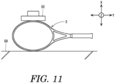
- FIG. 11 shows a method of measuring the side pressure stiffness value Gis.
- the tennis racket 2 is placed on a base 50, which is a rigid body.
- the width direction X of the racket 2 coincides with the vertical direction.
- the axial direction Y of the racket 2 coincides with the horizontal direction.
- a plate 52 which is a rigid body, is lowered, and thereby a load is applied to the racket 2.
- a displacement (cm) of the plate 52 is measured from when the load is 25 kgf to when the load is 50 kgf.
- the side pressure stiffness value Gis is calculated by dividing the load difference 25 kgf by the displacement (cm).
- the side pressure stiffness value Gis is measured in a state where the string 12 is removed from the frame 4.
- the side pressure stiffness value Gis is preferably greater than or equal to 45 kgf/cm, more preferably greater than or equal to 50 kgf/cm, and particularly preferably greater than or equal to 60 kgf/cm. In light of controllability, the side pressure stiffness value Gis is preferably less than or equal to 100 kgf/cm, more preferably less than or equal to 90 kgf/cm, and particularly preferably less than or equal to 80 kgf/cm.
- the in-plane stiffness index Gi is greater than or equal to 5000 and less than or equal to 8000.
- the tennis racket 2 having an in-plane stiffness index Gi of greater than or equal to 5000 has excellent repulsion performance.
- the in-plane stiffness index Gi is more preferably greater than or equal to 5100, and particularly preferably greater than or equal to 5150.
- the tennis racket 2 having an in-plane stiffness index Gi of less than or equal to 8000 has excellent controllability.
- the in-plane stiffness index Gi is more preferably less than or equal to 7500, and particularly preferably less than or equal to 7200.
- the ratio (Git / Gis) of the top pressure stiffness value Git to the side pressure stiffness value Gis is preferably greater than or equal to 1.0 and less than or equal to 1.8.
- the tennis racket 2 When a ball is hit by the tennis racket 2 having the ratio (Git / Gis) within this range, the tennis racket 2 suitably bends in the in-plane direction. Therefore, torsion of the face 20 is less likely to occur.
- This racket 2 has excellent repulsion performance.
- the ratio (Git / Gis) is more preferably greater than or equal to 1.1, and particularly preferably greater than or equal to 1.2.
- the ratio (Git / Gis) In light of repulsion performance, the ratio (Git / Gis) is more preferably less than or equal to 1.7, and particularly preferably less than or equal to 1.6.
- the tennis racket 2 has a proper out-of-plane stiffness index Go.
- the out-of-plane stiffness index Go is calculated by a mathematical formula shown below.
- Go Gos ⁇ Goh
- Gos is a throat stiffness value (kgf/cm)
- Goh is a ball-hitting face stiffness value (kgf/cm).
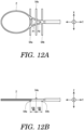
- FIGS. 12A and 12B show a method of measuring the throat stiffness value Gos.
- a first bar 54a, a second bar 54b, and a third bar 54c are prepared.
- the material of these bars 54 is steel.
- Each bar 54 has a circular cross-sectional shape having a radius of 5.0 mm.
- Each bar 54 extends along the width direction X.
- the distance between the first bar 54a and the third bar 54c in the axial direction Y is 100 mm
- the distance between the third bar 54c and the second bar 54b in the axial direction Y is 100 mm.
- the position of the first bar 54a is shifted toward the head 14 side from one end P1 of each throat 16.
- the position of the second bar 54b is shifted toward the grip 6 side from the other end P2 of each throat 16.
- the racket 2 is placed on the first bar 54a and the second bar 54b.
- the width direction X and the axial direction Y of the racket 2 coincide with the horizontal direction.
- the third bar 54c is lowered, and thereby a load is applied to the tennis racket 2.
- a displacement (cm) of the third bar 54c is measured from when the load is 25 kgf to when the load is 50 kgf.
- the throat stiffness value Gos is calculated by dividing the load difference 25 kgf by the displacement (cm).
- the throat stiffness value Gos is measured in a state where the string 12 is removed from the frame 4.
- the throat stiffness value Gos is preferably greater than or equal to 350 kgf/cm, more preferably greater than or equal to 370 kgf/cm, and particularly preferably greater than or equal to 400 kgf/cm. In light of controllability, the throat stiffness value Gos is preferably less than or equal to 480 kgf/cm, more preferably less than or equal to 460 kgf/cm, and particularly preferably less than or equal to 440 kgf/cm.
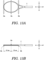
- FIGS. 13A and 13B show a method of measuring the ball-hitting face stiffness value Goh.
- a first bar 56a, a second bar 56b, and a third bar 56c are prepared.
- the material of these bars 56 is steel.
- Each bar 56 has a circular cross-sectional shape having a radius of 10.0 mm.
- Each bar 56 extends along the width direction X.
- the distance between the first bar 56a and the third bar 56c in the axial direction Y is 170 mm
- the distance between the third bar 56c and the second bar 56b in the axial direction Y is 170 mm.
- the first bar 56a is positioned at the top of the head 14.
- the racket 2 is placed on the first bar 56a and the second bar 56b.
- the width direction X and the axial direction Y of the racket 2 coincide with the horizontal direction.
- the third bar 56c is lowered, and thereby a load is applied to the tennis racket 2.
- a displacement (cm) of the third bar 56c is measured from when the load is 25 kgf to when the load is 50 kgf.
- the ball-hitting face stiffness value Goh is calculated by dividing the load difference 25 kgf by the displacement (cm).
- the ball-hitting face stiffness value Goh is measured in a state where the string 12 is removed from the frame 4.
- the ball-hitting face stiffness value Goh is preferably greater than or equal to 100 kgf/cm, more preferably greater than or equal to 110 kgf/cm, and particularly preferably greater than or equal to 120 kgf/cm. In light of controllability, the ball-hitting face stiffness value Goh is preferably less than or equal to 170 kgf/cm, more preferably less than or equal to 160 kgf/cm, and particularly preferably less than or equal to 150 kgf/cm.
- the out-of-plane stiffness index Go is preferably greater than or equal to 45000 and less than or equal to 60000.
- the tennis racket 2 having an out-of-plane stiffness index Go of greater than or equal to 45000 has excellent repulsion performance.
- the out-of-plane stiffness index Go is more preferably greater than or equal to 46000, and particularly preferably greater than or equal to 47000.
- the tennis racket 2 having an out-of-plane stiffness index Go of less than or equal to 60000 has excellent controllability.
- the out-of-plane stiffness index Go is more preferably less than or equal to 55000, and particularly preferably less than or equal to 51000.
- the tennis racket 2 achieves both the in-plane stiffness index Gi falling within the range of greater than or equal to 5000 and less than or equal to 8000 and the out-of-plane stiffness index Go falling within the range of greater than or equal to 45000 and less than or equal to 60000.
- the tennis racket 2 is not only excellent in terms of repulsion performance, but also realizes a long contact time with a ball when hitting it. The repulsion performance and controllability of the tennis racket 2 are both excellent.
- the tennis racket 2 includes bias-type reinforcement fibers.
- the bias-type reinforcement fibers can contribute to achieving both the in-plane stiffness index Gi falling within the range of greater than or equal to 5000 and less than or equal to 8000 and the out-of-plane stiffness index Go falling within the range of greater than or equal to 45000 and less than or equal to 60000.
- the ratio of the mass of the bias-type reinforcement fibers to the total mass of the reinforcement fibers is preferably greater than or equal to 15%, more preferably greater than or equal to 20%, and particularly preferably greater than or equal to 23%. This ratio is preferably less than or equal to 50%, more preferably less than or equal to 40%, and particularly preferably less than or equal to 35%.
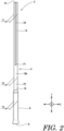
- reference sign Pt denotes the top of the head 14; reference sign P1 denotes one end of each throat 16; and reference sign P2 denotes the other end of each throat 16.
- the end P1 is joint where the head 14 is joined to the throat 16. It is clear from FIG. 2 that the head 14 has a constant thickness from the top to the joint P1 (see also FIG. 1 ).
- an arrow T1 indicates the thickness of the top.
- the throats 16 have a constant thickness from the end P1 to the other end P2 (see also FIG. 1 ).
- an arrow T2 indicates the thickness of the throats 16.
- the shaft 18 has a constant thickness over its entirety.
- an arrow T3 indicates the thickness of the shaft 18.
- the thickness T2 and the thickness T3 are each equal to the thickness T1.
- the thickness of the frame 4 is constant except the yoke 22.
- the tennis racket 2 thus configured can achieve both the in-plane stiffness index Gi falling within the range of greater than or equal to 5000 and less than or equal to 8000 and the out-of-plane stiffness index Go falling within the range of greater than or equal to 45000 and less than or equal to 60000.
- the maximum value of the thickness of the frame 4 is preferably less than 26.0 mm. In other words, preferably, at any part of the frame 4, the thickness thereof is less than 26.0 mm.
- the tennis racket 2 thus configured can achieve both the in-plane stiffness index Gi falling within the range of greater than or equal to 5000 and less than or equal to 8000 and the out-of-plane stiffness index Go falling within the range of greater than or equal to 45000 and less than or equal to 60000.
- the maximum value of the thickness of the frame 4 is more preferably less than or equal to 24.5 mm, and particularly preferably less than or equal to 23.5 mm.
- the maximum value of the thickness of the frame 4 is preferably greater than or equal to 17.0 mm, more preferably greater than or equal to 19.0 mm, and particularly preferably greater than or equal to 20.0 mm.
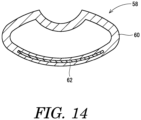
- FIG. 14 is a sectional view of a part of a tennis racket 58 according to another embodiment.
- FIG. 14 shows a frame 60.
- the frame 60 includes a damper 62.
- the damper 62 is sandwiched between fiber reinforced layers.
- the damper 62 can suppress vibration that propagates to the tennis player holding the tennis racket 58. This allows the player to have an excellent hitting feeling.
- the components of the racket 58, except the damper 62, are the same in configuration as those of the racket 2 shown in FIGS. 1 to 9 .
- the damper 62 is formed from a polymer composition.
- the polymer composition contains a base polymer.
- the polymer composition may contain additive agents as necessary. Examples of a suitable base polymer for the damper 62 include polyurethanes, styrene-based elastomers, and acrylic elastomers.
- the damper 62 may be foam.
- a preferable position of the damper 62 is a position in the outer side of the head in the width direction X. Another preferable position of the damper 62 is a position in each throat.
- the vibration damping rate of the tennis racket 58 in the out-of-plane direction thereof is greater than or equal to 0.5%.
- the racket 58 having a vibration damping rate of greater than or equal to 0.5% in the out-of-plane direction provides an excellent hitting feeling.
- the vibration damping rate in the out-of-plane direction is more preferably greater than or equal to 0.6%, and particularly preferably greater than or equal to 0.7%.
- FIGS. 15A and 15B show a method of measuring an out-of-plane natural frequency of the tennis racket 58.
- the racket 58 is suspended by a cord 64.
- the axial direction Y of the racket 58 coincides with the vertical direction.
- a head 66 is positioned above a shaft 68.
- a grip tape has been peeled off from the shaft 68.
- a string has been removed from the head 66.
- An acceleration pickup 70 is mounted to the head 66.
- the acceleration pickup 70 is mounted such that it is positioned on the outermost side of the head 66 in the width direction X.
- the acceleration pickup 70 is oriented in the thickness direction Z.
- the acceleration pickup 70 has a mass of 3.5 g.
- a point Ph on the opposite side of the head 66 from the acceleration pickup 70 is excited by an impulse hammer (not shown).
- a typical impulse hammer is available from PCB Piezotronics, Inc.
- Input vibration measured by a force pickup included in the impulse hammer and response vibration measured by the acceleration pickup 70 are fed to a frequency analyzer via an amplifier.
- a typical frequency analyzer is "Dynamic Signal Analyzer" available from Hewlett-Packard Company. Based on a transfer function obtained by the frequency analyzer, an out-of-plane natural vibration damping rate is calculated.
- ⁇ n out-of-plane primary natural vibration
- ⁇ is a peak width in the case of a transfer function To (see FIG. 16 ).
- Tn is the transfer function of the out-of-plane primary natural vibration.
- a tennis racket of Example 1 was fabricated.
- the frame of the racket was fabricated to include a plurality of fiber reinforced layers including reinforcement fibers.
- the ratio of the mass of bias-type reinforcement fibers to the total mass of the reinforcement fibers was 25%.
- the maximum thickness of the racket was 21.5 mm.
- the tennis players evaluated and rated the hitting feeling of each tennis racket during the rally in accordance with the following grading system.
- Example 1 Example 2
- Example 3 Comp.
- Example 1 Comp.
- Example 2 Face Area [sqin] 98 95 100 98 98 Mass [mm] 305 310 300 305 305 Balance [mm] 315 310 320 315 315
- Overall Length [mm] 686 686 686 686 Maximum Thickness [mm] 21.5 20.5 23.0 21.5 21.0 Gi 5,171 7,184 7,185 6,586 3,680 Go 50,174 47,484 49,987 41,779 39,214
- Initial Velocity [km/h] 120.4 120.6 120.4 120.0 120.2 Controllability
- Example 3 Comp.
- Example 4 Comp.
- Example 5 Comp.
- a racket including: a frame including a head; and a string that is stretched on the head and that forms a ball-hitting face, wherein: a maximum value of a thickness of the frame is less than 26.0 mm; an in-plane stiffness index Gi that is a product of a top pressure stiffness value Git (kgf/cm) and a side pressure stiffness value Gis (kgf/cm) is greater than or equal to 5000 and less than or equal to 8000; and an out-of-plane stiffness index Go that is a product of a throat stiffness value Gos (kgf/cm) and a ball-hitting face stiffness value Goh (kgf/cm) is greater than or equal to 45000 and less than or equal to 60000.
- the frame includes a pair of throats that are continuous with the head and a shaft that is continuous with the throats;
- the head has a constant thickness T1 from a top of the head to joints where the head is joined to the respective throats;
- the throats have a constant thickness T2;
- the shaft has a constant thickness T3; and the thickness T2 and the thickness T3 are each equal to the thickness T1.
- the frame includes a damper; and a vibration damping rate of the racket in an out-of-plane direction thereof is greater than or equal to 0.5%.
- the racket as described above is suitable also for use in, for example, soft tennis, squash, padel, and badminton.
- the above descriptions are merely illustrative examples, and various modifications can be made without departing from the principles of the present invention.
Landscapes
- Health & Medical Sciences (AREA)
- General Health & Medical Sciences (AREA)
- Physical Education & Sports Medicine (AREA)
- Pulmonology (AREA)
- Laminated Bodies (AREA)
Applications Claiming Priority (1)
| Application Number | Priority Date | Filing Date | Title |
|---|---|---|---|
| JP2023184851A JP2025073785A (ja) | 2023-10-27 | 2023-10-27 | ラケット |
Publications (1)
| Publication Number | Publication Date |
|---|---|
| EP4545155A1 true EP4545155A1 (de) | 2025-04-30 |
Family
ID=92909561
Family Applications (1)
| Application Number | Title | Priority Date | Filing Date |
|---|---|---|---|
| EP24202665.6A Pending EP4545155A1 (de) | 2023-10-27 | 2024-09-25 | Schläger |
Country Status (4)
| Country | Link |
|---|---|
| US (1) | US20250135309A1 (de) |
| EP (1) | EP4545155A1 (de) |
| JP (1) | JP2025073785A (de) |
| KR (1) | KR20250061623A (de) |
Cited By (1)
| Publication number | Priority date | Publication date | Assignee | Title |
|---|---|---|---|---|
| EP4656259A1 (de) * | 2024-05-28 | 2025-12-03 | Sumitomo Rubber Industries, Ltd. | Schläger |
Citations (4)
| Publication number | Priority date | Publication date | Assignee | Title |
|---|---|---|---|---|
| JPH0515617A (ja) | 1991-07-09 | 1993-01-26 | Sumitomo Rubber Ind Ltd | テニスラケツトフレーム |
| JPH06269514A (ja) * | 1993-03-16 | 1994-09-27 | Sumitomo Rubber Ind Ltd | テニスラケット |
| JPH1033719A (ja) * | 1996-07-19 | 1998-02-10 | Sumitomo Rubber Ind Ltd | ラケット |
| JP2013022361A (ja) * | 2011-07-25 | 2013-02-04 | Dunlop Sports Co Ltd | ラケットフレーム |
-
2023
- 2023-10-27 JP JP2023184851A patent/JP2025073785A/ja active Pending
-
2024
- 2024-09-25 KR KR1020240130149A patent/KR20250061623A/ko active Pending
- 2024-09-25 EP EP24202665.6A patent/EP4545155A1/de active Pending
- 2024-10-09 US US18/910,201 patent/US20250135309A1/en active Pending
Patent Citations (4)
| Publication number | Priority date | Publication date | Assignee | Title |
|---|---|---|---|---|
| JPH0515617A (ja) | 1991-07-09 | 1993-01-26 | Sumitomo Rubber Ind Ltd | テニスラケツトフレーム |
| JPH06269514A (ja) * | 1993-03-16 | 1994-09-27 | Sumitomo Rubber Ind Ltd | テニスラケット |
| JPH1033719A (ja) * | 1996-07-19 | 1998-02-10 | Sumitomo Rubber Ind Ltd | ラケット |
| JP2013022361A (ja) * | 2011-07-25 | 2013-02-04 | Dunlop Sports Co Ltd | ラケットフレーム |
Cited By (1)
| Publication number | Priority date | Publication date | Assignee | Title |
|---|---|---|---|---|
| EP4656259A1 (de) * | 2024-05-28 | 2025-12-03 | Sumitomo Rubber Industries, Ltd. | Schläger |
Also Published As
| Publication number | Publication date |
|---|---|
| JP2025073785A (ja) | 2025-05-13 |
| US20250135309A1 (en) | 2025-05-01 |
| KR20250061623A (ko) | 2025-05-08 |
Similar Documents
| Publication | Publication Date | Title |
|---|---|---|
| US4983242A (en) | Tennis racquet having a sandwich construction, vibration-dampening frame | |
| US4129634A (en) | Method for preparing a composite high strength to weight structure having shell and sleeved core | |
| CA1065362A (en) | Racket frames for tennis, badminton, squash, etc | |
| AU608254B2 (en) | Tennis racquet | |
| EP4545155A1 (de) | Schläger | |
| JP2019155060A (ja) | 縦軸線に関して複数方向の可撓性を高めた構成のラケット | |
| US6688997B2 (en) | Racket with reduced yoke rigidity | |
| CN100428969C (zh) | 球类运动的球拍 | |
| JP3970865B2 (ja) | ラケットフレーム | |
| JP4041031B2 (ja) | ラケットフレーム | |
| US6692377B2 (en) | Graphite shaft with foil modified torsion | |
| US11944877B2 (en) | Racket | |
| EP4656257A1 (de) | Schläger | |
| EP4656259A1 (de) | Schläger | |
| EP3922327A1 (de) | Schläger | |
| CN115382177A (zh) | 具有改进的手柄组件的球拍 | |
| US20050043124A1 (en) | Racket frame | |
| EP4098334A1 (de) | Federballschläger | |
| EP4098331A1 (de) | Federballschläger | |
| EP4098332A1 (de) | Federballschläger | |
| WO2022145200A1 (ja) | バドミントンラケット | |
| US6358165B1 (en) | Throatless squash racquet | |
| WO2022145199A1 (ja) | バドミントンラケット | |
| EP4098333A1 (de) | Federballschläger | |
| JP2022103635A (ja) | バドミントンラケット |
Legal Events
| Date | Code | Title | Description |
|---|---|---|---|
| PUAI | Public reference made under article 153(3) epc to a published international application that has entered the european phase |
Free format text: ORIGINAL CODE: 0009012 |
|
| STAA | Information on the status of an ep patent application or granted ep patent |
Free format text: STATUS: THE APPLICATION HAS BEEN PUBLISHED |
|
| AK | Designated contracting states |
Kind code of ref document: A1 Designated state(s): AL AT BE BG CH CY CZ DE DK EE ES FI FR GB GR HR HU IE IS IT LI LT LU LV MC ME MK MT NL NO PL PT RO RS SE SI SK SM TR |
|
| STAA | Information on the status of an ep patent application or granted ep patent |
Free format text: STATUS: REQUEST FOR EXAMINATION WAS MADE |
|
| 17P | Request for examination filed |
Effective date: 20250715 |
|
| P01 | Opt-out of the competence of the unified patent court (upc) registered |
Free format text: CASE NUMBER: UPC_APP_0005150_4545155/2026 Effective date: 20260212 |
|
| STAA | Information on the status of an ep patent application or granted ep patent |
Free format text: STATUS: EXAMINATION IS IN PROGRESS |