EP4545231A2 - Dispositif de chanfreinage d'une pièce - Google Patents
Dispositif de chanfreinage d'une pièce Download PDFInfo
- Publication number
- EP4545231A2 EP4545231A2 EP25151995.5A EP25151995A EP4545231A2 EP 4545231 A2 EP4545231 A2 EP 4545231A2 EP 25151995 A EP25151995 A EP 25151995A EP 4545231 A2 EP4545231 A2 EP 4545231A2
- Authority
- EP
- European Patent Office
- Prior art keywords
- workpiece
- axis
- machining
- holder
- linear axis
- Prior art date
- Legal status (The legal status is an assumption and is not a legal conclusion. Google has not performed a legal analysis and makes no representation as to the accuracy of the status listed.)
- Pending
Links
Images



Classifications
-
- B—PERFORMING OPERATIONS; TRANSPORTING
- B23—MACHINE TOOLS; METAL-WORKING NOT OTHERWISE PROVIDED FOR
- B23F—MAKING GEARS OR TOOTHED RACKS
- B23F19/00—Finishing gear teeth by other tools than those used for manufacturing gear teeth
- B23F19/10—Chamfering the end edges of gear teeth
-
- B—PERFORMING OPERATIONS; TRANSPORTING
- B23—MACHINE TOOLS; METAL-WORKING NOT OTHERWISE PROVIDED FOR
- B23F—MAKING GEARS OR TOOTHED RACKS
- B23F19/00—Finishing gear teeth by other tools than those used for manufacturing gear teeth
- B23F19/10—Chamfering the end edges of gear teeth
- B23F19/102—Chamfering the end edges of gear teeth by milling
- B23F19/105—Chamfering the end edges of gear teeth by milling the tool being an end mill
-
- B—PERFORMING OPERATIONS; TRANSPORTING
- B23—MACHINE TOOLS; METAL-WORKING NOT OTHERWISE PROVIDED FOR
- B23F—MAKING GEARS OR TOOTHED RACKS
- B23F23/00—Accessories or equipment combined with or arranged in, or specially designed to form part of, gear-cutting machines
- B23F23/006—Equipment for synchronising movement of cutting tool and workpiece, the cutting tool and workpiece not being mechanically coupled
Definitions
- the present invention relates to a device for chamfering a toothed workpiece, comprising a workpiece spindle with a workpiece holder mounted so as to be rotatable about a rotational axis for holding the workpiece, a tool spindle with a tool holder mounted so as to be rotatable about a rotational axis for holding an end mill, wherein the tool spindle is movable relative to the workpiece holder via at least one linear axis of the device, and a control with a machining function which, for chamfering a toothed workpiece, rotates the workpiece held in the workpiece holder by controlling the workpiece spindle, while an end mill held in the tool holder engages the edge to be machined.
- Such a device is known from the DE 20 2012 008 601 U1
- the end mill used there has a truncated cone-shaped tool head and is moved from above or below to the respective edge of the toothed workpiece in order to chamfer it.
- the tool spindle is moved via at least one movement axis of the device in such a way that the The end mill, which is mounted in the tool holder, is guided along the contour of the workpiece edge to be machined, while the workpiece is rotated about its axis of rotation.
- the device for chamfering is arranged on the back of a machine tool on which the gearing is produced, and thus allows chamfering of the workpiece in the same clamping in which the gearing was produced.
- the DE 20 2012 008 601 U1 However, the known device for chamfering can only be used on easily accessible gear edges. Furthermore, the speed at which the chamfering can be performed is limited, and the end mill is subject to high wear.
- the DE 10 2009 020 771 A1 also describes the chamfering of a workpiece using an end mill. However, here a 6-axis industrial robot is used to move the tool spindle.
- a device known as the "Gratomat” is also used for chamfering.
- This device uses an end mill with a cylindrical outer surface. This end mill rests on the tooth edge under preload and thus follows the contour of the edge when the workpiece rotates.
- the tool spindle is pivotally mounted for this purpose and preloaded against the edge by a spring.
- the Gratomat process results in significant fluctuations in the chamfer size and shape from the tooth tip to the tooth root. Furthermore, the process speed is low, and the end mill is subject to high wear.
- the object of the present invention is therefore to provide an improved device for chamfering.
- the machining function varies the rotational speed across a tooth gap, i.e. the machining of different areas of a tooth gap takes place with different rotational speeds of the workpiece.
- a tooth gap is preferably understood as an area formed by two opposing tooth flanks, the intermediate tooth root, and half of the adjacent tooth tips. Tooth flanks are the active, This refers to the areas of the gearing designed for rolling on other gearing. In an involute gearing, the tooth flanks correspond to the involute areas of the gearing.
- the rotational speed of the workpiece across the tooth gap fluctuates by more than 30% of the maximum value, more preferably by more than 60% of the maximum value.
- the machining function uses the same rotational speed profile for each tooth gap. The variation in speed is therefore repeated for each tooth gap of the tooth edge to be machined.
- the machining function varies the rotational speed across a tooth gap such that the cutting volume of the end mill per unit time and/or the relative speed between the edge and the end mill across the tooth gap fluctuates by no more than 30% of the maximum value, preferably by no more than 15% of the maximum value.
- the machining function varies the rotational speed of the workpiece over at least one tooth flank, i.e. different rotational speeds are used in different areas of a tooth flank.
- the machining function varies the rotational speed of the workpiece across a tooth gap such that a left tooth flank is machined at a different rotational speed and/or rotational acceleration than a right tooth flank.
- the average, minimum, and/or maximum rotational speed and/or rotational acceleration for one tooth flank can be greater than for the other tooth flank.
- the rotational speed of the workpiece on the left and right flanks differs by more than 10% of the larger value, more preferably by more than 30% of the larger value.
- the machining function varies the rotational speed across a tooth gap such that a left tooth flank is machined with a rotational speed profile that is not symmetrical to the rotational speed profile used on the right tooth flank.
- a different rotational speed profile for the left and right flanks can also be used for spur gears.
- the gearing itself can be symmetrical or asymmetrical on the left and right flanks.
- the machining function varies the rotational speed across a tooth gap such that the workpiece is machined at a greater rotational acceleration in the region of the tooth root than on at least one and preferably on both tooth flanks.
- the average, minimum and/or maximum rotational acceleration in the region of the tooth root can be greater than on at least one and preferably on both tooth flanks.
- the region of the tooth root can in particular be used to accelerate from a first rotational speed, which is used for chamfering the root end of one flank, to another rotational speed, which is used for chamfering the root end of the other flank.
- the machining function varies the rotational speed across a tooth gap such that the workpiece is machined at a higher rotational speed and/or rotational acceleration in the area of the tooth tip than at least one and preferably both tooth flanks and/or in the area of the tooth root.
- the average, minimum and/or maximum rotational speed and/or rotational acceleration in the area of the tooth tip must be greater than on at least one and preferably on both tooth flanks and/or in the area of the tooth root.
- the rotational acceleration in the sense of the present invention can also be a negative acceleration, whereby the above information preferably refers to the respective absolute value of the acceleration.
- the workpiece is machined in the same direction of rotation across the entire tooth gap and thus the entire tooth edge. Furthermore, in many cases, the rotational speed will not drop to zero.
- the machining function therefore comprises a machining mode in which the entire tooth gap and thus the entire tooth edge is machined with the same direction of rotation of the workpiece and/or the rotational speed does not drop to zero.
- the machining function therefore comprises a machining mode in which the direction of rotation of the workpiece changes when passing through a tooth gap.
- the machining function can have a machining mode in which the rotational speed drops to zero when passing through a tooth gap.
- this can be done as part of the change in the direction of rotation.
- the rotational speed remains at zero for a certain period of time. This can be advantageous even without a subsequent change in the workpiece's rotation direction, allowing the end mill to move relative to the workpiece while the workpiece is stationary.
- the processing function can comprise one or more of the above-mentioned processing modes. If multiple processing modes are provided, the processing function preferably has a selection function, in particular as part of the operator guidance.
- the tool spindle can be moved relative to the workpiece holder via at least one movement axis of the device, in particular via at least one and preferably several linear axes.
- the first aspect of the present invention can be used in a first variant in a device in which the end mill rests under preload on the tooth edge and therefore follows the contour of the edge during a rotational movement of the workpiece, in particular without a movement of the tool spindle relative to the workpiece spindle controlled by drives of the device.
- the tool spindle is preferably pivotally mounted and preloaded against the edge by a spring, in particular as is known from the Gratomat process.
- a considerable advantage results from varying the rotational speed of the workpiece.
- the one or more linear axes can be used for the initial approach of the end mill to the gearing.
- the tool spindle is movable relative to the workpiece holder via at least one movement axis of the device, wherein the machining function for chamfering a toothed workpiece held in the workpiece holder moves the tool spindle relative to the workpiece spindle via the at least one movement axis such that a milling cutter held in the tool holder is guided in a controlled manner along the contour of an edge of the workpiece to be machined, while the workpiece is rotated about its rotation axis.
- This controlled movement of the tool spindle is preferably synchronized with the workpiece rotation.
- control commands and/or a predetermined contour can be stored in a memory of the control system, on the basis of which a corresponding control of the movement axes of the device, in particular via a control of the workpiece spindle and the at least one movement axis with which the tool spindle can be moved relative to the workpiece spindle, takes place in such a way that the end mill travels the predetermined contour.
- the tool spindle can be moved via a first linear axis X in a direction perpendicular to the axis of rotation of the workpiece holder and/or via a second linear axis Z parallel to the axis of rotation of the workpiece holder.
- these axes can be used for the initial positioning of the end mill to the edge, but can no longer be moved during the machining of an edge.
- the machining function controls the tool spindle via the first linear axis X and/or the second linear axis Z in such a way that a finger milling cutter accommodated in the tool holder is guided in a controlled manner along the contour of an edge of the workpiece to be machined, while the workpiece is rotated about its axis of rotation.
- control is carried out in such a way that the end mill is guided along the contour in a controlled manner at least over a partial area of the tooth gap by a superposition of a movement of the first linear axis X and the second linear axis Z.
- control can be such that the end mill, when passing through a tooth gap, is guided along the contour by a movement of both the first linear axis X and the second linear axis Z.
- the travel movements by the first linear axis X and the second linear axis Z do not have to occur in short bursts.
- the relative movement between the tool spindle and the workpiece spindle during the chamfering of an edge can be carried out exclusively via one or both of these axes.
- other movement axes of the device can also be used to control the end mill mounted in the tool holder. to guide along the contour of the edge of the workpiece to be machined, in particular one or more swivel axes.
- the machining function is designed to control the tool spindle via the first linear axis X and/or the second linear axis Z such that different axial regions of the lateral surface of a milling cutter mounted in the tool holder engage with the edge of the workpiece to be machined. This distributes wear over the length of the milling cutter. This is preferably achieved by a travel movement along the second linear axis Z.
- different axial areas of the lateral surface of the end mill can engage with the edge of the workpiece to be machined.
- the machining function is designed such that the tool holder is guided along the contour of the edge to be machined, at least over partial areas of a tooth gap, only via the second linear axis Z and not via the first linear axis X, and/or is guided along the contour of the edge to be machined, only via the first linear axis X and not via the second linear axis Z.
- the travel movement via the first linear axis X has the advantage that machining is possible even with interfering contours that are very close to the edge.
- the travel movement via the second linear axis Z has the advantage that wear can be distributed over the length of the end mill.
- the relative movement between the tool spindle and the workpiece spindle during chamfering of an edge can occur, at least over partial areas of a tooth gap, exclusively via the first linear axis X or the second linear axis Z, i.e., no other axes of the machining head are moved.
- other movement axes of the device can also be used to guide the end mill mounted in the tool holder in a controlled manner along the contour of the edge of the workpiece to be machined, in particular one or more pivot axes.
- the machining function is designed for use with a finger milling cutter having a cylindrical outer surface or a conical outer surface with a cone angle of less than 20°, preferably less than 10°.
- the end mill can have a rounded head. This can be used for machining the tooth root if necessary. However, for reasons of even wear, it is preferable to work only with the conical or cylindrical outer surface.
- the machining function operates with an orientation of the tool holder such that a milling cutter mounted in the tool holder extends from the tool holder through the tooth gap to the edge of the gearing it is machining. This allows the edge to be machined even in the presence of interfering contours.
- the present invention therefore comprises a device for chamfering a toothed workpiece, comprising a workpiece spindle with a workpiece holder mounted so as to be rotatable about a rotational axis for receiving the workpiece, a tool spindle with a tool holder mounted so as to be rotatable about a rotational axis for receiving an end mill, wherein the tool spindle is movable relative to the workpiece holder via a first linear axis X in a direction perpendicular to the rotational axis of the workpiece holder and/or via a second linear axis Z parallel to the rotational axis of the workpiece holder, and a controller with a machining function which, for chamfering a toothed workpiece received in the workpiece holder, moves the tool spindle via the first linear axis X and/or the second linear axis Z relative to the workpiece spindle in such a way that an end mill received
- the machining function is designed such that the position of the tool spindle relative to the workpiece holder is changed via the second linear axis Z in order to engage different axial regions of the lateral surface of a finger milling cutter received in the tool holder with the edge of the workpiece to be machined.
- This change in position via the second linear axis Z can occur during the machining of a tooth edge and in particular over a tooth gap, and/or during the machining of different tooth edges of a workpiece and/or during the machining of the same tooth edge of several identical workpieces in successive steps.
- the machining function is designed such that the tool holder is guided along the contour of the edge to be machined, at least over partial areas of a tooth gap, only via the second linear axis Z and not via the first linear axis X.
- the relative movement between the tool spindle and the workpiece spindle during the chamfering of an edge can take place, at least over partial areas of a tooth gap, exclusively via the second linear axis Z, i.e. no other axes of the machining head are moved.
- other movement axes of the device can also be used in order to guide the end mill accommodated in the tool holder in a controlled manner along the contour of the edge of the workpiece to be machined, in particular one or more pivot axes.
- the machining function is adapted to the use of an end mill with a cylindrical outer surface or a conical outer surface with a cone angle of less than 20°, preferably of less than 10°. This allows the machining of edges that are difficult to access due to interfering contours and/or the distribution of wear over the axial length of the end mill.
- the end mill can have a rounded head. This can be used for machining the tooth root if necessary. However, for reasons of even wear, it is preferable to work only with the conical or cylindrical outer surface.
- the machining function is designed such that work is carried out with an orientation of the tool holder through which an end mill held in the tool holder runs from the tool holder through the tooth gap to the edge of the gearing that it is machining.
- this can be a machining mode of the machining function.
- the machining function is designed such that an end mill held in the tool holder only protrudes with its tip beyond that end face of the workpiece whose edge with the gearing is being machined by the end mill.
- the individual variants of the second aspect can each be used individually and independently of one another and are independently the subject of the present invention. However, at least two of the variants are preferably combined with one another, more preferably three variants, and more preferably all variants.
- the tool spindle is not pivoted when passing through a tooth gap. If there is a swivel axis over which the tool spindle can be swiveled, this can be used for the initial alignment of the end mill relative to the workpiece.
- the tool spindle can be pivoted about a first pivot axis A or A2.
- the first pivot axis A runs perpendicular to the rotation axis of the workpiece holder and/or parallel to the first linear axis X.
- first pivot axis A2 can run in a plane which is perpendicular to the first linear axis X.
- the present invention comprises a device for chamfering a toothed workpiece, comprising a workpiece spindle with a workpiece holder rotatably mounted about a rotational axis for receiving the workpiece, a tool spindle with a tool holder rotatably mounted about a rotational axis for receiving a milling cutter, wherein the tool spindle is rotatably mounted about a rotational axis in a direction perpendicular to the axis of rotation of the workpiece holder and via a second linear axis Z parallel to the axis of rotation of the workpiece holder relative to the workpiece holder, and a controller with a machining function which, for chamfering a toothed workpiece held in the workpiece holder, moves the tool spindle via the first linear axis X and/or the second linear axis Z relative to the workpiece spindle in such a way that an end mill held in the tool holder is guided in a
- the third linear axis enables simplified and/or more uniform chamfering, especially of helical gears.
- the third linear axis can be used in particular to position the end mill for machining an edge of the gearing in a zero position relative to the gearing, in which the end mill is arranged centrally in the tooth gap, wherein the contact point between the end mill and the edge to be machined is laterally shifted with respect to a plane which runs through the axis of rotation of the workpiece holder parallel to the first linear axis X.
- the movement of the end mill to follow the contour of the edge can then take place without a movement of the third linear axis Y or V.
- the third linear axis Y or V can also be used to follow the contour of the edge during chamfering of an edge.
- the tool spindle for chamfering is arranged via the third linear axis Y or V in such a way that the rotational axis of the tool holder does not intersect the rotational axis of the workpiece holder and preferably runs skewed to it.
- the third aspect of the present invention is the subject matter of the present invention independently of the other aspects. It can be combined with the first and/or second aspects of the present invention in possible embodiments of the present invention.
- the machining function is designed such that no chamfer is created in the area of the tooth root, or a smaller chamfer is created than on the tooth flank. This is achieved, in particular, by appropriately controlling the movement axes of the gear cutting machine, via which the end mill is moved along the contour of the edge.
- This procedure takes into account the fact that in order to produce a larger chamfer in the area of the tooth root, a finger milling cutter with a correspondingly small radius must be used, since the tooth root usually has a very small radius.
- end mills with a diameter larger than the diameter of the tooth root can be used without causing a collision of the end mill with a tooth flank when machining the edge of the tooth root.
- the tool spindle can be pivoted via a second pivot axis A2, which is aligned perpendicular to its axis of rotation and runs in a plane that is perpendicular to the first linear axis X.
- the second pivot axis A2 can be provided in addition to or instead of the first pivot axis A.
- the second swivel axis A2 allows the adjustment of the chamfer angle and/or the machining of upper and lower edges of a gear.
- the tool spindle can be pivoted via the second pivot axis A2 from a first machining position for machining a lower edge of the workpiece into a second machining position for machining an upper edge.
- the second pivot axis A2 allows pivoting of the axis of rotation of the tool holder in a plane in which the first pivot axis A runs.
- the second swivel axis A2 can be a positioning axis.
- the machining positions can be defined by stops, especially adjustable stops.
- the second swivel axis A2 is an NC axis.
- the second swivel axis A2 can also be used during chamfering to move the end mill along the edge to be machined in a controlled manner, particularly to influence the chamfer angle.
- the at least one movement axis and/or the first linear axis and/or the second linear axis Z and/or the third linear axis Y or V and/or the first pivot axis A are NC axes.
- the device comprises a threading sensor.
- a threading sensor This allows the position of the tooth gaps and/or tooth tips of the gearing to be determined and from this the correct assignment between the end mill and the gearing to be made.
- it can be a contactless threading sensor, for example an inductive sensor.
- the threading sensor is arranged on a machining head that is movable along at least one axis of motion and also supports the tool spindle.
- the at least one axis of motion can therefore be used to position both the threading sensor and the end mill relative to the gear teeth.
- the tool spindle is pivotably mounted on the machining head, which carries the threading sensor, via a second pivot axis A2, so that the tool spindle can be pivoted into a neutral position by the machining function, while the toothing is measured by the threading sensor.
- the machining function is designed such that a chamfer is created only in partial areas of the second edge. In particular, those areas of the edge where there is insufficient material available to create a chamfer can be omitted during chamfering.
- the end mill can therefore also be used for shaft gears where the tooth root essentially corresponds to the radius of the shaft and therefore no tooth edge is present in this area. Since the end mill is guided along the tooth edge under NC control while the workpiece is rotated, only the tooth tips and flanks can be chamfered, for example, leaving the tooth root free.
- control comprises a function for inputting a parameter of the desired chamfer shape and/or a function for determining the chamfer shape from one or more parameters of the gap contour of the gearing to be chamfered.
- the chamfer shape parameter may be a chamfer width and/or a chamfer depth and/or a chamfer angle and/or a symmetry property.
- the one or more parameters of the gap contour of the gearing can be one or more parameters that can be entered via a function for setting up the gearing process with which the gearing is created. This eliminates the need for a CAD model of the gearing and/or chamfer.
- control of the device is preferably programmed such that the devices according to the invention automatically carry out the steps described above with regard to their functioning and/or application, and/or automatically carry out the methods described below.
- the present invention firstly protects a device, as described in more detail above, which is suitable for receiving an end mill in the tool holder and for performing the applications described above.
- the device comprises a control system that enables the use of such tools for chamfering an edge.
- the present invention also includes a device as described above in which a milling cutter is accommodated in the tool holder.
- the device can be a stand-alone chamfering machine.
- the device according to the invention is a chamfering machine integrated into a gear machining center.
- the present invention further relates to a gear cutting machining center comprising a device as described above, a gear cutting machine, and a workpiece changer.
- the gear cutting machine is preferably a gear shaping machine, a gear skiving machine, or a gear milling machine.
- the gear cutting and chamfering of the workpieces in the gear cutting center preferably take place in parallel with the cycle time.
- workpieces cut by the gear cutting machine are transported via the workpiece changer to the chamfering device according to the present invention, where they are chamfered, while the next workpiece is already being cut on the gear cutting machine.
- Chamfering of the workpiece between a roughing step and a finishing step is also conceivable, for which the workpiece is preferably moved from the gear cutting machine to the device according to the invention and back again.
- the workpiece changer is a ring automation, wherein furthermore preferably the chamfering device according to the invention and the gear cutting machine are arranged at different angular positions of the ring automation.
- the gear cutting machine and the device according to the invention have separate workpiece holders.
- the workpiece changer transfers a workpiece after the gear cutting operation of the gear cutting machine from the workpiece holder there to the workpiece holder of the chamfering device according to the invention.
- the gear cutting center can also have multiple workpiece holders in which the workpieces for gear cutting and chamfering remain.
- the workpiece holders are preferably moved from the gear cutting machine to the device according to the invention and/or vice versa.
- the workpiece changer is preferably used to place workpieces from an external transport line or other processing stations onto the workpiece holder or workpiece holders and to remove them from them.
- the device according to the invention can also be designed as a separate, stand-alone machine.
- This machine preferably receives toothed workpieces from a transport line and/or automated system for chamfering. The correspondingly machined workpieces are then preferably transferred back to a transport line and/or automated system.
- the present invention further comprises a method for chamfering an edge of a toothed workpiece by means of a device as described above.
- the tool spindle is moved relative to the workpiece spindle via the at least one linear axis in such a way that a finger milling cutter held in the tool holder is guided in a controlled manner along the contour of an edge of the workpiece to be machined, while the workpiece is rotated about its axis of rotation.
- Chamfering is preferably carried out as described in more detail above.
- the method and the device according to the invention can be used both for machining an edge of an external toothing and for machining an edge of an internal toothing.
- the workpiece can be a gear with only one toothing.
- Such workpieces can also be chamfered using a chamfer-cut process.
- a tool specifically adapted to the toothing is used.
- a customized, expensive tool is required.
- the present invention allows flexible chamfering of essentially any geometry.
- the method and the device according to the invention can be used both for machining an edge of an involute gear and for machining an edge of a non-involute gear.
- the method and the device according to the invention are preferably used for chamfering a workpiece with multiple teeth or other interfering contours.
- the method according to the invention and the device according to the invention can be used for machining at least one edge located next to an interfering contour, in particular an edge of a multiple toothing.
- the size of the chamfer can vary across the tooth gap, taking into account the allowance of subsequent processes.
- the chamfer size across the tooth gap and, in particular, the tooth height can be designed differently so that after a subsequent process, in which any flank allowance remaining during chamfering is removed, the chamfer size on the finished workpiece is the same everywhere.
- the material removal across the tooth gap and, in particular, the tooth flank can vary in size, which is taken into account by creating a chamfer of varying size.
- the subsequent process can, for example, involve hard finishing, particularly by grinding.
- a chamfer is produced in a first processing step, wherein the first chamfer is measured and correction values are determined therefrom, which are taken into account in a second processing step.
- the first machining step is performed on a first workpiece and the second machining step on a second workpiece.
- the chamfer can be machined and measured to its full depth during the process start-up, and the machining can be corrected for the subsequent workpiece.
- the first and second machining steps are performed on the same workpiece, with the first chamfer not yet reaching the desired depth and then being milled to full depth in the second machining step.
- This approach is particularly interesting for expensive workpieces, e.g., larger workpieces or very small batch sizes.
- control of the device can have an input function via which the measured values can be entered and/or transmitted to the control, wherein a calculation function of the control determines the correction values.
- the invention describes a method for deburring or chamfering gear teeth using a face mill.
- the gear teeth can be straight or helical spur gear teeth, which can be either cylindrical or conical (beveled gear teeth).
- the gears can be either symmetrical or asymmetrical, meaning the profile angles of the left and right flanks can, but do not have to, be different.
- the gear profiles can be freely selected, including involute.
- the gears can be designed as external gears or as internal gears.
- the end mills can be cylindrical or conical.
- the process described below differs from the process underlying the Gratomat® in that, while in the Gratomat® the milling cutter is pressed against the gear teeth by a spring force, in the process presented here the exact movement kinematics are calculated and implemented by the machine. This allows a specified chamfer to be created.
- the implementation of the movement kinematics is preferably carried out by the machine's NC axes.
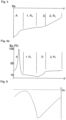
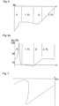
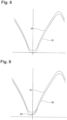
- the speed of the table rotation in the method proposed here is not constant, in contrast to the Gratomat ® method (see Fig. 4 and 6 ), but varies across the tooth gap.
- the direction of rotation of the milling cutter can be freely selected.
- coordinates are used here for generalized, not necessarily independent coordinates.
- the rotation axis of a gear always coincides with the z- axis in its rest system.
- This kinematic chain serves primarily as a mathematical description of the invention described here.
- the calculation of the coordinates A 1 , ..., A N S can be performed using a coordinate transformation.
- Fig. 1a and b show an embodiment of a working area of a gear cutting machine with a movement apparatus present there, whose coordinate axes consistent with those used in the definition of the kinematic chain.
- Rotation axis B3 of the tool holder - ⁇ T angle of rotation of the tool.
- Second swivel axis A2 - ⁇ angle of attack of the milling cutter to the toothing.
- first swivel axis A - ⁇ Axis crossing angle between the rotation axis of the milling cutter and the rotation axis of the gear ( z -axis).
- Third linear axis Y or V - y T Amount of translation of the cutter from the center of the toothing.
- First linear axis X - d Distance of the cutter from the center of the toothing.
- Second linear axis Z - z T Amount of translation of the milling cutter along the rotation axis of the workpiece.
- Rotation axis C2 of the workpiece holder - ⁇ W angle of rotation of the workpiece.
- the tool here the end mill
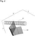
- a gap see Fig. 2
- the tool is fed into a gap (see Fig. 2 ) and generally moves along one or more of the axes given by the parameters ⁇ , ⁇ , y T , d, z T and ⁇ W .
- the rotation axis of the tool is inclined (generally skewed) to the rotation axis of the workpiece.
- curves on the bevel e.g., the beginning and end of the bevel, can be specified as general smooth Jordan curves.
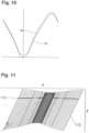
- the curves generally do not have to lie in a frontal section plane (see Fig. 11 for a possible defined start of a chamfer).
- workpieces that do not have a flat front side can also be accepted.
- Possible workpieces can be Fig. 12
- the face shapes shown in the top row can be chamfered using both the Gratomat® process and the process presented here.
- the bottom row shows the tooth flanks, which are chamfered or stepped, as an example, starting at the pitch circle.
- the Gratomat® process cannot machine such workpieces, whereas the process presented here can chamfer this workpiece.
- the Jordan curve is selected accordingly.
- the beginning of the chamfer so that a chamfer of equal height is created across the entire flank width.
- Such a curve could be chosen as a downward displacement of the non-planar face by a defined amount.
- the width of the chamfer can also be selected so that after chamfering, a width that changes across the tooth gap is initially produced, but which is designed with regard to material removal in subsequent processes so that the finished workpiece has a chamfer of the same height across the entire tooth gap.
- the relations are structured as follows: three equations for point equality and one equation for the tangential contact. This means that four free variables are required to solve the system of equations consisting of the four equations. For the first contact, these are the two variables that parameterize the surface of the milling cutter: the angle of rotation of the tool ⁇ W , and another parameter, e.g. the cutter height z T . These relations can, for example, be formulated and solved for a discrete number of points on the curve. This gives the required parameters as a function of the position of the point on the chamfer.
- the chamfer can now be specified very freely.
- the chamfer angle along the gap contour can be specified.
- the milling cutter is universally applicable, as the chamfer shape is generated by the machining kinematics.
- the chamfer shape is essentially limited only by the diameter of the milling cutter, since if this diameter is selected too large compared to the gear, collisions occur, particularly in the tooth root, which must be avoided.
- the chamfer can be symmetrical (see Fig. 8 ) or asymmetrical (see Fig. 10 ) can be selected.
- the implicitly defined chamfer can be determined using a material removal simulation based on the previously determined kinematics and tool. This material removal simulation takes into account the geometry of the milling cutter and the trajectory of the milling cutter relative to the gear teeth during the machining process, determining where material is removed and, based on the unmachined geometry, determining the final contour of the gear teeth and thus also the chamfer. Such material removal simulations are known for various machining processes.
- the invention also provides that the control of the device has a function for inputting a parameter of the desired chamfer shape.
- This parameter of the chamfer shape can be, for example, a chamfer width and/or a chamfer depth and/or a chamfer angle and/or a symmetry property.
- the controller preferably includes a function for determining the chamfer shape from one or more parameters of the gap contour of the gear to be chamfered.
- these would include, among others, the profile angle(s), the helix angle, the tooth thickness, and the shape of the tooth root, as well as, if applicable, the shape of a tip chamfer.
- these can be one or more parameters that are already present in the controller from the submission of the gear cutting process with which the gear is created, or that can be entered via a function for setting up the gear cutting process.
- the chamfer shape is determined based on the entered chamfer shape parameter and one or more gap contour parameters.
- This variant of the invention is characterized by the fact that only a few parameters need to be entered in addition to those already entered in the control system for defining the gearing, thus simplifying work preparation. Furthermore, a connection to an external computer system and data transfer from an external computer system are not necessary.
- An extended form of the invention provides that the chamfer width and/or the chamfer depth and/or the chamfer angle can be specifically modified via the profile of the gearing, and the control system preferably provides a corresponding input function. For example, it can be input that the chamfer angle is larger in the area of the tooth tip than in the area of the tooth root.
- the most general form of defining the chamfer is that it is transferred digitally to the control system, for example via a 2D or 3D data format.
- the controller can determine the kinematics that best approximates the chamfer, or even, at least theoretically, produces it exactly. How good the approximation is will depend on the variant of the invention used.
- the invention provides a control which determines the parameters ⁇ , ⁇ , y T in such a way that the chamfer is approximated as closely as possible. This determination is preferably carried out via a compensation calculation, which determines the parameters such that a distance function that measures the distance of the achievable chamfer from the desired chamfer is minimized.
- a simple distance function here would be a sum of the squared distances from a discrete number of points of the achieved contour 82 to the desired curve.
- the parameters essentially have the following effect on the chamfer shape: ⁇ increases or decreases the chamfer angle along the tooth contour; ⁇ and y T increase the chamfer angle on one flank and decrease it on the other, causing a change in the chamfer angle from tip to toe; ⁇ W increases the chamfer width on one flank and decreases it on the other.
- ⁇ increases or decreases the chamfer angle along the tooth contour
- ⁇ and y T increase the chamfer angle on one flank and decrease it on the other, causing a change in the chamfer angle from tip to toe
- ⁇ W increases the chamfer width on one flank and decreases it on the other.
- the control preferably has a display function which graphically displays the desired chamfer shape and the theoretically achievable chamfer shape in order to enable a visual comparison of the two chamfer shapes, and/or a display function for displaying the deviation between the desired chamfer shape and the theoretically achievable chamfer shape.
- the milling cutter is moved along the curve that parameterizes the profile line at a constant feed rate.
- the distance resulting from the traversed curve is referred to here as the milling progress ⁇ .
- the rotational speed and acceleration are greatest in the area of the tooth tips. Furthermore, the two flanks are machined at different rotational speeds. In the area of the tooth root, the rotational speed changes accordingly from one flank to the other, resulting in a greater rotational acceleration here than on the flanks.
- the rotational speed can also vary within one or both flanks.
- Another special case of the general case would be to specify a smooth Jordan curve on the chamfer (e.g. the start of the chamfer), as in the first special case, but this time the parameters z T , ⁇ , ⁇ and y T are set fixed and only the kinematics are calculated, how d must be moved to produce the chamfer.
- the advantage of this method is that chamfers can also be applied in places that allow only little space in the z -direction. This method is also preferably applied to these problematic conditions because, in contrast to the first special case, the milling cutter would only be loaded in one area.
- Another special case is the combination of the two previous special cases. Neither z T nor d is fixed.
- a smooth Jordan curve is specified on the chamfer (e.g. the start of the chamfer)
- the parameters ⁇ , ⁇ and y T are fixed, but now five instead of just four variables must be used to solve the system of equations. This means that an underdetermined system of equations must be solved. For this reason, it is necessary to specify an additional condition (this could be the exact position of the contact point on the milling cutter) or to perform a compensation calculation, whereby the milling cutter load can be distributed over the entire milling cutter. Since this uses a larger area of the milling cutter, this leads to a longer milling cutter service life.
- the displacement d can be determined in such a way that the cutter only has a fixed, defined A bit extends beyond the root radius.
- the displacement z T can be selected such that there is no collision with the collar in the critical area, but in the non-critical area, wear is distributed as far as possible over the entire cutter length. Therefore, in the critical area, d is primarily moved, but in the non-critical area, d is left constant and z T is moved.
- Another special case is chamfering internal gears. For these, it is necessary to work across the table center in certain cases. This may be necessary if the gear is not directly accessible at one end.
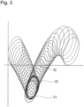
- the ellipses on the right and left flanks share only one point of contact with the profile line, whereas the bold ellipses share multiple intersection points with the profile line. This means that, assuming the cutter is moved along the profile line, the tool not only creates a chamfer, but also damages the flank or tooth root (marked ellipses in Fig. 3 ).
- these collisions can also be prevented by using a ball milling cutter whose diameter is smaller than the diameter of the root rounding.
- a chamfer is created on the workpiece using the method described here, it is possible to correct the chamfer. Corrections may be necessary if the exact machine geometry is unknown or if the gear teeth are centered manually.
- One possible correction would be the desired axial displacement of a chamfer. This means that a desired correction affects the yT value.
- a desired correction affects the yT value.
- the yT parameter can be determined to produce the desired chamfer.
- This principle can also be applied to the remaining parameters ⁇ , ⁇ , and d .
- the influences on the chamfer shape in particular the symmetry of the chamfer, the axial position of the chamfer, the chamfer angle, and the progression of the chamfer angle across the entire gap, can be determined. Once these influences are known, the parameters can be determined to achieve the desired chamfer shape.
- the corrections described here may be necessary if, for example, the geometry of the end mill does not exactly match that assumed in the calculation. This can be caused, for example, by inaccurate measurement of the end mill and/or wear.
- the corrections described here may also be necessary alternatively or additionally if, for example, the relative position of the end mill to the gear does not exactly correspond to that assumed in the calculation. This can be caused, for example, by inaccurate measurement of the fixture and/or by non- or insufficiently compensated heat transfer of the fixture and/or by imprecise centering of the end mill in the gear.
- the required corrections can be entered via the control system, transferred digitally to the machine, or determined from a measurement of the achieved chamfer and a subsequent target-actual comparison.
- the measurement can take place either in the fixture or on an external measuring machine. Measurement in the machine offers the advantage that the process adjustment and determination of the corrections are fully automated. can be done if the measured values are transferred directly to the control system.
- the variant of the invention that does not require the movement of all available axes during chamfering has the advantage, compared to a variant in which all axes are moved, that not all axes have to be designed as NC axes, or at least not all have to be suitable for movement during chamfering. This allows for a more cost-effective design of the device.
- Fig. 1a and 1b show a possible embodiment of a device according to the invention for chamfering a toothed workpiece 5.
- the device has a workpiece spindle 1 with a workpiece holder 2 rotatably mounted about a rotation axis C2 for receiving the workpiece 5.
- the device has a tool spindle 3 with a tool holder 4 rotatably mounted on a rotation axis B3 for receiving an end mill 6.
- the workpiece spindle 1 is arranged on a machine bed 7, which is connected to a machine stand or machine frame 8, on which a machining head 9 is arranged, which carries the tool spindle 3.
- the machining head 9 and/or the tool spindle 3 arranged on the machining head 9 can be moved relative to the workpiece spindle 1 over several machine axes.
- the axis configuration in the example is selected as follows:
- the machining head can be moved via a first linear axis X in a direction perpendicular to the rotational axis C2 of the workpiece holder 2. This allows the end mill to be moved toward the workpiece in a plane perpendicular to the rotational axis of the workpiece spindle.
- the machining head can be moved via a second linear axis Z in a direction parallel to the rotational axis C2 of the workpiece holder 2. This allows the end mill to be moved in the axial direction relative to the workpiece 5.
- a first pivot axis A is also provided, which runs parallel to the first linear axis X and allows pivoting of the machining head 9.
- a third linear axis Y is provided, which allows the machining head to be moved in a direction perpendicular to the first linear axis X and the second linear axis Z.
- a third linear axis V could also be used, which is arranged between the machining head and the first pivot axis A and can therefore be pivoted via the first pivot axis A.
- the third linear axes Y and V allow the end mill 6 to be moved relative to a plane that runs through the rotation axis C2 of the workpiece holder parallel to the X-axis, and thus a lateral movement relative to the center of the workpiece 5.
- a second pivot axis A2 is provided, via which the tool spindle 3 is pivotably mounted on the machining head 9.
- the second pivot axis A2 runs perpendicular to the first pivot axis A and preferably intersects it.
- the second pivot axis A2 allows the angle of attack of the end mill 6 to be adjusted relative to the toothing of the workpiece.
- the second swivel axis A2 allows the angle of the end mill 6 relative to the rotation axis C2 of the workpiece holder and thus the chamfer angle for machining
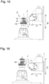
- the second swivel axis A2 also allows the end mill to be moved from a first swivel position, as shown in Fig. 15 shown, and which is used to machine a lower edge, into a second pivoting position, as shown in Fig. 16 shown, and which is used to machine an upper edge.
- the end mill can also be pivoted into a neutral position, as shown in Figs. 13 and 14 shown, and in which the end mill was pivoted away from the workpiece.
- the rotary axis D1 of the workpiece holder 2, the first linear axis X, and the second linear axis Z are all NC axes.
- the third linear axis Y and V, as well as the first swivel axis A, are also NC axes.
- the rotary axis B3 of the tool holder 4 does not have to be designed as an NC axis, since it only serves the non-synchronized drive of the end mill 6.
- the second pivot axis A2 can be designed as an adjustment axis.
- the positions of the pivot axis A2 can be defined manually or via stops, for example.
- the second swivel axis A2 can also be designed as an NC axis. This allows for flexible movement to the aforementioned positions for machining different edges, flexible adjustment of the cutter's approach angle during chamfering, and, if necessary, even variation of the approach angle across the tooth gap.
- Threading sensors 10 and 11 are also arranged on the machining head 9. Threading sensor 10 is used to measure external gears, while threading sensor 11 is used to measure internal gears. Typically, a machining head will only have one of the two sensors. A contactless sensor, in particular an inductive sensor, is preferably used.
- Fig. 13 The measurement of a workpiece 5 with external gearing using the threading sensor 10 is shown.
- the tool spindle 3 is pivoted into a neutral position via the second pivot axis A2.
- the threading sensor 10 is moved to the gearing, and the workpiece is rotated via the rotation axis C2.
- the threading sensor detects the position of the teeth or tooth grooves. By detecting the position of the teeth or tooth grooves, the end mill can then be positioned in the correct position relative to the tooth gap during the subsequent chamfering operation.
- Fig. 14 shows the measurement of a workpiece 5' with internal gearing.
- the threading sensor has a sensor arm 12 that extends into the internal gearing.
- two sensor arms 12 and 12' are provided, oriented in opposite directions, to enable measurement of internal gearing from both above and below.
- Figs. 15 and 16 The chamfering of the already in Fig. 1a, 1b and 13 shown workpiece 5 with an external toothing by the device according to the invention is shown in Figs. 15 and 16 shown.
- the workpiece 5 has several gear teeth 13, 14, and 15. Chamfering the central gear 14 is particularly problematic, since the two outer gear teeth 13 and 15 form interfering contours that must be taken into account during chamfering.
- the end mill 6 is therefore positioned in such a way that it extends from the tool holder 4 through the tooth gap to the contact point with the respective edge of the gear to be machined. Therefore, only the tip of the end mill 6 protrudes beyond the respective end face of the gear to be machined. This allows even gears such as the internal gear 14 with interfering edges located very close to the respective end edge to be chamfered.
- Fig. 15 shows the chamfering of a lower edge of the center gear of workpiece 5.
- the tool spindle with the end mill 6 was pivoted into a lower machining position via the second pivot axis A2.
- the angle of the chamfer is adjusted via the pivot position of the tool spindle 3 using the second pivot axis A2.
- the first linear axis X is preferably used exclusively or almost exclusively to machine the lower edge in order to move the end mill along the tooth edge in a controlled manner, and a movement via the second linear axis Z is completely or largely dispensed with.
- This allows the entire tooth edge to be chamfered via a front area of the end mill 6, so that the end mill with its tip only protrudes slightly beyond the corresponding lower end edge of the central toothing 14.
- this procedure has the disadvantage that not the entire length of the end mill is used for gear machining, so that wear is concentrated in the front area of the end mill.
- Fig. 16 shows the chamfering of an upper edge of the central gear 14.
- the tool spindle with the end mill 6 was pivoted via the second pivot axis A2 into an upper machining position, in which the end mill 6 rests on the upper edge.
- the chamfer angle can be adjusted via the second pivot axis A2.
- the end mill 6 is moved exclusively or predominantly along the tooth edge via the second linear axis Z.
- This has the advantage that different axial areas of the end mill's lateral surface are used for chamfering, so that wear can be evenly distributed across the end mill.
- a movement along the X-axis can either be omitted entirely, or both the first linear axis X and the second linear axis Z can be used to generate the travel movement.
- the first linear axis X is predominantly used for machining the tooth roots
- the second linear axis Z is predominantly used for machining the tooth flanks. This takes into account the fact that an additional interference contour exists in the area of the tooth roots due to the proximity to the workpiece shaft. When machining the tooth flanks, however, the distance to the shaft is greater, so that the second linear axis Z can be used predominantly here.
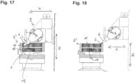
- Fig. 17 to 20 show the chamfering of a workpiece with internal gearing.
- the workpiece 5' has several gears 16 and 17.
- a collar 18 is provided between the upper internal gear 16 and the lower internal gear 17. Due to the poor accessibility and the interfering contours, chamfering the inner edges of the upper gear 16 and the lower gear 17 is particularly problematic.
- Fig. 17 shows the chamfering of the lower edge of the upper internal gear 16.
- the machining head 9 with the tool spindle 4 was moved into a position above the gear using the first linear axis X.
- the end mill 6 therefore runs obliquely from above into the gear and rests on the lower edge of the internal gear 16.
- the end mill is positioned with the workpiece spindle 4 in the lower machining position, which is reached via the second swivel axis A2.
- the second linear axis Z is used to move the end mill in the axial direction into the internal gearing.
- the movement of the end mill along the contour of the edge during chamfering is preferably carried out mainly or exclusively via the first linear axis X.
- Fig. 18 shows the chamfering of an upper edge of the upper gear 16.
- the end mill 6 extends from the tool holder 4 from the end face of the gear into the gear, so that the tip of the end mill is located within the gear. Since no interfering contours need to be considered here, the end mill 6 can be moved exclusively or predominantly along the second linear axis Z along the contour of the tooth edge during chamfering.
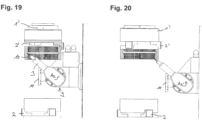
- Figs. 19 and 20 show the chamfering of the lower toothing 17 of the internally toothed workpiece 5'. Since at least the upper edge of the lower toothing 17 cannot be machined from the top side of the toothing, a second workpiece spindle 1' with a corresponding second workpiece holder 2' is provided.
- the two workpiece spindles are arranged coaxially and can be moved toward each other in the axial direction, so that a workpiece held in the first workpiece holder 2 can be gripped by gripping jaws of the second workpiece holder 2'.
- the first workpiece holder 2 then releases the workpiece, so that it is now held in the second workpiece holder 2'.
- the second workpiece holder 2' is arranged or can be arranged such that the machining head 9 with the tool spindle 3 can be moved under the workpiece 5'.
- At least one of the two workpiece holders can be moved axially in the direction of the rotation axis D1.
- Fig. 20 the lower and thus outer tooth edge of the lower toothing 17 is chamfered.
- the machining is carried out analogously to the chamfering in Fig. 18 .
- a recalibration of the gearing for threading the end mill may be omitted, or a recalibration of the workpiece held in the second workpiece holder 2' may be necessary.
- the upper arm of the threading sensor 11 can be used in the same way as in Fig. 14 for the lower arm, except that now the threading sensor engages the gearing from below.
- the rotational speed of the workpiece 5 about the rotational axis C2 is varied during chamfering.
- the rotation of the workpiece occurs at a speed that varies across the tooth gap.
- the rotational speed is lower than when chamfering a tooth root and/or tip. This allows the cutting volume per unit of time to be influenced and preferably kept as constant as possible.
- Such a variation of the workpiece rotation speed also has advantages independent of the guidance of the end mill via NC axes of the gear cutting machine along the contour of the edge, and could therefore, for example, also be used in a process control that corresponds to the Gratomat process known from the state of the art, i.e. in which the end mill rests on the tooth edge under spring load.
- Particular advantages arise from the variation the rotational speed, however, in combination with the controlled guidance of the end mill via the NC axes of the machine along the tooth edge, as this enables considerably higher machining speeds.
- the third linear axis Y or V is also used, in particular for machining helical gears, in order to position the end mill 6 relative to the tooth gap.
- the machining head 9 is moved along the Y or V axis from the center of the gearing of the workpiece.
- the rotational axis B3 of the tool spindle therefore no longer intersects the rotational axis C2 of the workpiece spindle.
- the machining head is arranged such that the A axis no longer intersects the rotational axis D1 of the workpiece spindle, but runs past it at a distance.
- the rotational axis B3 of the tool spindle 3 preferably no longer intersects the first pivot axis A.
- the third linear axis Y or V for positioning the end mill 6 relative to the gearing makes it possible, particularly with helical gears, to achieve a symmetrical chamfer on the left and right flanks with fewer travel movements during chamfering.
- the third linear axis Y or V can be used exclusively to position the end mill in a fixed position for chamfering.
- the position along the third linear axis can also be varied during chamfering, and in particular across the tooth gap.
- the first swivel axis A and the second swivel axis A2 can also be used either for the one-time positioning of the end mill relative to the tooth edge, or for the controlled guidance of the end mill along the tooth edge during gear cutting. If necessary, one or even both of the two swivel axes can be omitted.
- the end mill preferably used is a end mill with a cylindrical or conical outer surface or envelope.
- the cone angle is preferably less than 20°, in particular less than 10°.
- a cone is advantageous in this case for machining a tooth gap with the smaller diameter of the end mill, while increasing the stability of the end mill in the remaining areas due to the larger diameter.
- the area of the tooth root is preferably machined with a front area of the end mill, while the tooth flanks are machined with an area located further back on the end mill.
- All of the described procedures are preferably provided by one or more processing functions of the control system of the device and are used automatically by the device for chamfering one and preferably for processing a large number of identical workpieces.
Landscapes
- Engineering & Computer Science (AREA)
- Mechanical Engineering (AREA)
- Gear Processing (AREA)
- Milling Processes (AREA)
Applications Claiming Priority (2)
| Application Number | Priority Date | Filing Date | Title |
|---|---|---|---|
| DE102018108632.6A DE102018108632A1 (de) | 2018-04-11 | 2018-04-11 | Vorrichtung zur Anfasbearbeitung eines Werkstücks |
| EP19164586.0A EP3552744B1 (fr) | 2018-04-11 | 2019-03-22 | Dispositif et procédé de traitement par chanfreinage d'une pièce à usiner |
Related Parent Applications (2)
| Application Number | Title | Priority Date | Filing Date |
|---|---|---|---|
| EP19164586.0A Division EP3552744B1 (fr) | 2018-04-11 | 2019-03-22 | Dispositif et procédé de traitement par chanfreinage d'une pièce à usiner |
| EP19164586.0A Division-Into EP3552744B1 (fr) | 2018-04-11 | 2019-03-22 | Dispositif et procédé de traitement par chanfreinage d'une pièce à usiner |
Publications (2)
| Publication Number | Publication Date |
|---|---|
| EP4545231A2 true EP4545231A2 (fr) | 2025-04-30 |
| EP4545231A3 EP4545231A3 (fr) | 2025-08-13 |
Family
ID=65904315
Family Applications (2)
| Application Number | Title | Priority Date | Filing Date |
|---|---|---|---|
| EP25151995.5A Pending EP4545231A3 (fr) | 2018-04-11 | 2019-03-22 | Dispositif de chanfreinage d'une pièce |
| EP19164586.0A Active EP3552744B1 (fr) | 2018-04-11 | 2019-03-22 | Dispositif et procédé de traitement par chanfreinage d'une pièce à usiner |
Family Applications After (1)
| Application Number | Title | Priority Date | Filing Date |
|---|---|---|---|
| EP19164586.0A Active EP3552744B1 (fr) | 2018-04-11 | 2019-03-22 | Dispositif et procédé de traitement par chanfreinage d'une pièce à usiner |
Country Status (8)
| Country | Link |
|---|---|
| US (1) | US11980957B2 (fr) |
| EP (2) | EP4545231A3 (fr) |
| JP (1) | JP7058240B2 (fr) |
| CN (1) | CN110355426B (fr) |
| DE (1) | DE102018108632A1 (fr) |
| FI (1) | FI3552744T3 (fr) |
| HU (1) | HUE071458T2 (fr) |
| PL (1) | PL3552744T3 (fr) |
Families Citing this family (15)
| Publication number | Priority date | Publication date | Assignee | Title |
|---|---|---|---|---|
| DE102017112450A1 (de) | 2017-06-06 | 2018-12-06 | Liebherr-Verzahntechnik Gmbh | Vorrichtung und Verfahren zum Anfasen eines innenverzahnten Werkstücks |
| DE102017112416A1 (de) * | 2017-06-06 | 2018-12-06 | Liebherr-Verzahntechnik Gmbh | Vorrichtung und Verfahren zum Anfasen eines innenverzahnten Werkstücks |
| DE102020001428A1 (de) | 2020-03-05 | 2021-09-09 | Gleason-Pfauter Maschinenfabrik Gmbh | Verfahren zur Zahnkantenbearbeitung |
| CN112332611B (zh) * | 2020-09-30 | 2022-05-03 | 株洲壹星科技股份有限公司 | 一种电动机槽楔定位及切割方法 |
| DE102021105099A1 (de) * | 2021-03-03 | 2022-09-08 | Maher Sabbagh | Zahnradbearbeitungsmaschine und Verfahren zum Herstellen eines Zahnrades |
| DE102021002704A1 (de) | 2021-05-25 | 2021-07-29 | Gleason-Pfauter Maschinenfabrik Gmbh | Verfahren zur verzahnungsbearbeitung, insbesondere zur zahnkantenbearbeitung |
| CN113305369B (zh) * | 2021-05-28 | 2022-10-21 | 湖南中大创远数控装备有限公司 | 螺旋锥齿轮机床及螺旋锥齿轮倒棱方法 |
| CN114019908B (zh) * | 2021-10-27 | 2024-04-12 | 南京工业大学 | 一种螺旋锥齿轮齿廓弧面倒棱控制方法 |
| CN114850586A (zh) * | 2022-06-13 | 2022-08-05 | 南京工大数控科技有限公司 | 一种定倾角主轴极坐标倒角方法 |
| JP2024011835A (ja) * | 2022-07-15 | 2024-01-25 | 株式会社不二越 | 複合加工機 |
| DE102022004131A1 (de) | 2022-11-07 | 2024-05-08 | Gleason-Pfauter Maschinenfabrik Gmbh | Verfahren zur verzahnungsbearbeitung mit darauffolgendem anfasen |
| DE102023210085B3 (de) * | 2023-10-13 | 2025-01-23 | Renk Gmbh | Verfahren und System zum Erstellen einer Zahnfußkontur |
| DE102023135391A1 (de) * | 2023-12-15 | 2025-06-18 | Liebherr-Verzahntechnik Gmbh | Vorrichtung zur Anfasbearbeitung |
| DE102024104116A1 (de) * | 2024-02-14 | 2025-08-14 | Gleason-Pfauter Maschinenfabrik Gmbh | Verfahren zum Anfasen einer Zahnkante einer Werkstückverzahnung |
| CN119525580B (zh) * | 2024-10-22 | 2025-10-03 | 中国航发南方工业有限公司 | 一种用于外花键齿顶型面的倒圆加工方法 |
Citations (2)
| Publication number | Priority date | Publication date | Assignee | Title |
|---|---|---|---|---|
| DE102009020771A1 (de) | 2009-05-06 | 2010-11-11 | Kadia Produktion Gmbh + Co. | Bearbeitungsvorrichtung und Bearbeitungsverfahren zur spanabtragenden Bearbeitung komplex gekrümmter Werkstückkanten an Werkstücken |
| DE202012008601U1 (de) | 2012-09-10 | 2012-12-12 | Klingelnberg Gmbh | Werkzeugmaschine mit Anfas- und/oder Entgratvorrichtung |
Family Cites Families (29)
| Publication number | Priority date | Publication date | Assignee | Title |
|---|---|---|---|---|
| US1219481A (en) * | 1915-05-24 | 1917-03-20 | Lars August Peterson | Method of chamfering the teeth of gears. |
| CH530845A (de) * | 1970-11-03 | 1972-11-30 | Oerlikon Buehrle Ag | Vorrichtung zum Läppen von zwei Zahnrädern |
| FR2292550A1 (fr) * | 1974-11-28 | 1976-06-25 | Peugeot & Renault | Dispositif d'ebavurage et de chanfreinage de dentures de roues d'engrenage |
| DE3000295A1 (de) * | 1980-01-05 | 1981-07-09 | Präwema Präzisionswerkzeugmaschinenfabrik KG Maschinenkontor GmbH & Co, 3440 Eschwege | Fraesmaschine zum bearbeiten von zahnkanten |
| SU952483A1 (ru) * | 1981-01-04 | 1982-08-23 | Всесоюзный Научно-Исследовательский Инструментальный Институт | Способ бочкообразного закруглени торцев зубьев пр мозубых зубчатых колес,переключаемых осевым перемещением |
| JPS61152320A (ja) * | 1985-06-06 | 1986-07-11 | Howa Mach Ltd | 数値制御歯車面取盤 |
| JPS6234721A (ja) * | 1985-08-08 | 1987-02-14 | Howa Mach Ltd | 数値制御歯車面取盤 |
| KR870002069B1 (ko) * | 1985-08-27 | 1987-12-03 | 금성전선 주식회사 | 기어 이빨자동 모떼기 장치(Gear Tooth Chamfering Machine) |
| SU1395434A1 (ru) * | 1986-10-17 | 1988-05-15 | Витебское Специальное Конструкторское Бюро Зубообрабатывающих,Шлифовальных И Заточных Станков | Способ образовани фаски по торцу зуба зубчатого колеса |
| SU1634404A1 (ru) * | 1987-12-11 | 1991-03-15 | Новополоцкий Политехнический Институт Им.Ленинского Комсомола Белоруссии | Способ зубозакруглени колес и станок дл его осуществлени |
| DE4134925C1 (en) * | 1991-10-23 | 1992-11-05 | Praewema Werkzeugmaschinenfabrik Gmbh, 3440 Eschwege, De | Gear wheel machining fixture - has two cutter spindles with cutter head moving at angles |
| DE19701267A1 (de) | 1997-01-16 | 1998-07-23 | Werner Hermann Wera Werke | Werkzeugmaschine zum Abdachen der Stirnseiten der Zähne von Zahnrädern oder dergleichen |
| US7377731B1 (en) * | 2002-12-05 | 2008-05-27 | Arvin Joseph L | Chamfering cutting tool or grinding wheel and method of making and use thereof |
| DE202007016740U1 (de) * | 2006-12-02 | 2008-03-13 | Maschinenfabrik Rausch Gmbh & Co. Kg | Vorrichtung zum Entgraten eines Werkstücks |
| EP2480366B1 (fr) * | 2009-09-25 | 2013-11-06 | The Gleason Works | Dispositif pour chanfreiner et/ou ébarber les engrenages |
| DE202009015537U1 (de) * | 2009-11-17 | 2010-02-04 | Maschinenfabrik Rausch Gmbh & Co. Kg | Werkzeug |
| DE102011050498B4 (de) * | 2011-05-19 | 2024-02-15 | Profilator Gmbh & Co. Kg | Werkzeugmaschine zur Stirnkantenabdachung von Zahnrädern |
| DE102012018358A1 (de) * | 2012-08-20 | 2014-02-20 | Liebherr-Verzahntechnik Gmbh | Werkzeuganordnung |
| DE102013003804B4 (de) * | 2013-03-05 | 2015-02-26 | Emag Holding Gmbh | Verfahren und Vorrichtung zum Entgraten und Anfasen verzahnter Werkstücke |
| DE202013009805U1 (de) * | 2013-03-28 | 2014-01-10 | Liebherr-Verzahntechnik Gmbh | Vorrichtung zum Anfasen eines Werkstücks |
| DE102013015240A1 (de) * | 2013-03-28 | 2014-10-02 | Liebherr-Verzahntechnik Gmbh | Vorrichtung und Verfahren zum Anfasen eines Werkstücks |
| DE102014008475B4 (de) * | 2014-06-05 | 2023-02-23 | Gleason-Pfauter Maschinenfabrik Gmbh | Verfahren zum Bearbeiten eines Werkstücks, Werkzeuganordnung und Verzahnungsmaschine |
| DE102014218082B4 (de) * | 2014-09-10 | 2016-11-10 | Felsomat Gmbh & Co. Kg | Vorrichtung zur Wälzschälbearbeitung eines Werkstücks zur Fertigung einer Fase und zugehöriges Betriebsverfahren |
| DE102014014132A1 (de) * | 2014-09-30 | 2016-05-25 | Liebherr-Verzahntechnik Gmbh | Verfahren und Vorrichtung zum Anfasen und Entgraten verzahnter Werkstücke |
| DE102015104242A1 (de) * | 2015-03-20 | 2016-09-22 | Profilator Gmbh & Co. Kg | Verzahnungsverfahren mit Zahnnachbearbeitung |
| DE102015012603A1 (de) * | 2015-09-28 | 2017-03-30 | Liebherr-Verzahntechnik Gmbh | Verfahren zum Entgraten eines Zahnradrohlings |
| CN105665839A (zh) * | 2016-03-11 | 2016-06-15 | 天津精诚机床股份有限公司 | 一种立式螺旋锥齿轮倒棱机 |
| CN105834528A (zh) * | 2016-04-27 | 2016-08-10 | 太仓宝达齿条有限公司 | 一种齿轮倒角设备 |
| JP6794868B2 (ja) * | 2017-02-20 | 2020-12-02 | アイシン精機株式会社 | 複合歯切加工装置 |
-
2018
- 2018-04-11 DE DE102018108632.6A patent/DE102018108632A1/de active Pending
-
2019
- 2019-03-15 JP JP2019048256A patent/JP7058240B2/ja active Active
- 2019-03-22 PL PL19164586.0T patent/PL3552744T3/pl unknown
- 2019-03-22 HU HUE19164586A patent/HUE071458T2/hu unknown
- 2019-03-22 EP EP25151995.5A patent/EP4545231A3/fr active Pending
- 2019-03-22 EP EP19164586.0A patent/EP3552744B1/fr active Active
- 2019-03-22 FI FIEP19164586.0T patent/FI3552744T3/fi active
- 2019-04-10 US US16/380,617 patent/US11980957B2/en active Active
- 2019-04-11 CN CN201910289326.3A patent/CN110355426B/zh active Active
Patent Citations (2)
| Publication number | Priority date | Publication date | Assignee | Title |
|---|---|---|---|---|
| DE102009020771A1 (de) | 2009-05-06 | 2010-11-11 | Kadia Produktion Gmbh + Co. | Bearbeitungsvorrichtung und Bearbeitungsverfahren zur spanabtragenden Bearbeitung komplex gekrümmter Werkstückkanten an Werkstücken |
| DE202012008601U1 (de) | 2012-09-10 | 2012-12-12 | Klingelnberg Gmbh | Werkzeugmaschine mit Anfas- und/oder Entgratvorrichtung |
Also Published As
| Publication number | Publication date |
|---|---|
| US20190314911A1 (en) | 2019-10-17 |
| CN110355426A (zh) | 2019-10-22 |
| US11980957B2 (en) | 2024-05-14 |
| JP7058240B2 (ja) | 2022-04-21 |
| DE102018108632A1 (de) | 2019-10-17 |
| CN110355426B (zh) | 2024-06-18 |
| EP4545231A3 (fr) | 2025-08-13 |
| FI3552744T3 (fi) | 2025-03-24 |
| PL3552744T3 (pl) | 2025-07-07 |
| EP3552744A1 (fr) | 2019-10-16 |
| HUE071458T2 (hu) | 2025-08-28 |
| EP3552744B1 (fr) | 2025-02-19 |
| JP2019206071A (ja) | 2019-12-05 |
Similar Documents
| Publication | Publication Date | Title |
|---|---|---|
| EP3552744B1 (fr) | Dispositif et procédé de traitement par chanfreinage d'une pièce à usiner | |
| EP3724598B1 (fr) | Procédé et dispositif de mesure d'un outil pour l'usinage par génération | |
| EP2385885B1 (fr) | Dispositif et procédé pour tailler des dents dans des pièces et jeu d'outils correspondant | |
| EP2221693B1 (fr) | Procédé et dispositif de production de données de commande destinées à commander un outil sur une machine-outil comportant au moins 5 axes | |
| EP3147060B1 (fr) | Procede d'ebavurage d'une ebauche d'engrenage et dispositif pour la mise en oeuvre d'un tel procédé | |
| EP3230001B1 (fr) | Procédé de traitement d'une denture, ensemble d'outil et machine à denture | |
| EP2314404B1 (fr) | Procédé de traitement précis et dur des flancs de dents d'une roue dentée | |
| EP2823924A2 (fr) | Machine à dresser double | |
| EP3552743A1 (fr) | Dispositif et procédé de traitement par chanfreinage d'une pièce à dents à usiner | |
| EP3242175A2 (fr) | Procédé d'usinage des engrenages d'une pièce | |
| EP1319457B1 (fr) | Procédé d'usinage de roues dentées essentiellement cylindriques à denture intérieure ou extérieure | |
| EP1947538B1 (fr) | Procédé de commande d'un outil mobile, dispositif d'introduction tout comme machine de traitement | |
| EP1060712B1 (fr) | Dispositif et procédé de fabrication de prothèses dentaires | |
| EP3584025A1 (fr) | Procédé de rectification topologique de denture par génération d'une pièce de roue dentée et machine de rectification dotée d'une commande de rectification topologique de denture par génération d'une pièce de roue dentée | |
| EP3118699A2 (fr) | Procede de fabrication d'une piece dentee comprenant une geometrie de surface modifiee | |
| EP2420906B1 (fr) | Procédé et dispositif de production de données de commande pour la formation d'une dent d'une denture à renvoi à l'aide d'un traitement par fraisage d'une pièce usinée sur une machine-outil | |
| WO2013117558A1 (fr) | Machine-outil à commande numérique et procédé de commande d'un processus d'alignement automatique en rotation d'une roue dentée sur la machine-outil | |
| DE102013110130B4 (de) | Werkzeug, Verfahren und Maschine zum Erzeugen eines Verzahnungsprofils an einem Werkstück durch Wälzschälen | |
| DE102010051284B4 (de) | Verfahren und Werkzeugmaschine zum Herstellen von schrägstehenden Nuten in der Außen- oder Innenumfangsfläche eines rotationssymmetrischen Grundkörpers | |
| DE102024100637A1 (de) | Verfahren zur Herstellung eines verzahnten Werkstücks | |
| EP1080843A2 (fr) | Procédé et dispositif pour dressage par commande numérique de la roue de régulation d'une rectifieuse "sans centre" | |
| DE102017129651A1 (de) | Verfahren zur Verzahnbearbeitung eines Werkstücks | |
| DE102017129613A1 (de) | Verfahren zur Verzahnbearbeitung eines Werkstücks | |
| DE102017122447A1 (de) | Verfahren zur Herstellung eines Werkstücks mit einem nicht umlaufenden Profil mittels einer Drehmaschine | |
| DE102017122438B4 (de) | Verfahren zur Herstellung eines Werkstücks mit einem nicht umlaufenden Profil mit einer ebenen Fläche mittels einer Drehmaschine |
Legal Events
| Date | Code | Title | Description |
|---|---|---|---|
| PUAI | Public reference made under article 153(3) epc to a published international application that has entered the european phase |
Free format text: ORIGINAL CODE: 0009012 |
|
| STAA | Information on the status of an ep patent application or granted ep patent |
Free format text: STATUS: THE APPLICATION HAS BEEN PUBLISHED |
|
| AC | Divisional application: reference to earlier application |
Ref document number: 3552744 Country of ref document: EP Kind code of ref document: P |
|
| AK | Designated contracting states |
Kind code of ref document: A2 Designated state(s): AL AT BE BG CH CY CZ DE DK EE ES FI FR GB GR HR HU IE IS IT LI LT LU LV MC MK MT NL NO PL PT RO RS SE SI SK SM TR |
|
| REG | Reference to a national code |
Ref country code: DE Ref legal event code: R079 Free format text: PREVIOUS MAIN CLASS: B23F0023000000 Ipc: B23F0019100000 |
|
| PUAL | Search report despatched |
Free format text: ORIGINAL CODE: 0009013 |
|
| AK | Designated contracting states |
Kind code of ref document: A3 Designated state(s): AL AT BE BG CH CY CZ DE DK EE ES FI FR GB GR HR HU IE IS IT LI LT LU LV MC MK MT NL NO PL PT RO RS SE SI SK SM TR |
|
| RIC1 | Information provided on ipc code assigned before grant |
Ipc: B23F 19/10 20060101AFI20250710BHEP Ipc: B23F 23/00 20060101ALI20250710BHEP |
|
| STAA | Information on the status of an ep patent application or granted ep patent |
Free format text: STATUS: REQUEST FOR EXAMINATION WAS MADE |
|
| 17P | Request for examination filed |
Effective date: 20260205 |