EP4545276A1 - Buse pour un dispositif de construction par couches d'un composant, dispositif doté d'une telle buse et procédé de fabrication d'un composant - Google Patents
Buse pour un dispositif de construction par couches d'un composant, dispositif doté d'une telle buse et procédé de fabrication d'un composant Download PDFInfo
- Publication number
- EP4545276A1 EP4545276A1 EP23205692.9A EP23205692A EP4545276A1 EP 4545276 A1 EP4545276 A1 EP 4545276A1 EP 23205692 A EP23205692 A EP 23205692A EP 4545276 A1 EP4545276 A1 EP 4545276A1
- Authority
- EP
- European Patent Office
- Prior art keywords
- nozzle
- channel section
- channel
- component
- section
- Prior art date
- Legal status (The legal status is an assumption and is not a legal conclusion. Google has not performed a legal analysis and makes no representation as to the accuracy of the status listed.)
- Withdrawn
Links
Images
Classifications
-
- B—PERFORMING OPERATIONS; TRANSPORTING
- B29—WORKING OF PLASTICS; WORKING OF SUBSTANCES IN A PLASTIC STATE IN GENERAL
- B29C—SHAPING OR JOINING OF PLASTICS; SHAPING OF MATERIAL IN A PLASTIC STATE, NOT OTHERWISE PROVIDED FOR; AFTER-TREATMENT OF THE SHAPED PRODUCTS, e.g. REPAIRING
- B29C64/00—Additive manufacturing, i.e. manufacturing of three-dimensional [3D] objects by additive deposition, additive agglomeration or additive layering, e.g. by 3D printing, stereolithography or selective laser sintering
- B29C64/10—Processes of additive manufacturing
- B29C64/106—Processes of additive manufacturing using only liquids or viscous materials, e.g. depositing a continuous bead of viscous material
- B29C64/118—Processes of additive manufacturing using only liquids or viscous materials, e.g. depositing a continuous bead of viscous material using filamentary material being melted, e.g. fused deposition modelling [FDM]
-
- B—PERFORMING OPERATIONS; TRANSPORTING
- B29—WORKING OF PLASTICS; WORKING OF SUBSTANCES IN A PLASTIC STATE IN GENERAL
- B29C—SHAPING OR JOINING OF PLASTICS; SHAPING OF MATERIAL IN A PLASTIC STATE, NOT OTHERWISE PROVIDED FOR; AFTER-TREATMENT OF THE SHAPED PRODUCTS, e.g. REPAIRING
- B29C64/00—Additive manufacturing, i.e. manufacturing of three-dimensional [3D] objects by additive deposition, additive agglomeration or additive layering, e.g. by 3D printing, stereolithography or selective laser sintering
- B29C64/20—Apparatus for additive manufacturing; Details thereof or accessories therefor
- B29C64/205—Means for applying layers
- B29C64/209—Heads; Nozzles
-
- B—PERFORMING OPERATIONS; TRANSPORTING
- B33—ADDITIVE MANUFACTURING TECHNOLOGY
- B33Y—ADDITIVE MANUFACTURING, i.e. MANUFACTURING OF THREE-DIMENSIONAL [3D] OBJECTS BY ADDITIVE DEPOSITION, ADDITIVE AGGLOMERATION OR ADDITIVE LAYERING, e.g. BY 3D PRINTING, STEREOLITHOGRAPHY OR SELECTIVE LASER SINTERING
- B33Y10/00—Processes of additive manufacturing
-
- B—PERFORMING OPERATIONS; TRANSPORTING
- B33—ADDITIVE MANUFACTURING TECHNOLOGY
- B33Y—ADDITIVE MANUFACTURING, i.e. MANUFACTURING OF THREE-DIMENSIONAL [3D] OBJECTS BY ADDITIVE DEPOSITION, ADDITIVE AGGLOMERATION OR ADDITIVE LAYERING, e.g. BY 3D PRINTING, STEREOLITHOGRAPHY OR SELECTIVE LASER SINTERING
- B33Y30/00—Apparatus for additive manufacturing; Details thereof or accessories therefor
Definitions
- the invention relates to a nozzle for a device for the layered construction of a component, a device with such a nozzle and a method for producing a component.
- a nozzle according to the preamble of claim 1 is known, for example, from DE 20 2012 001 873 U1 known.
- 3D printing In recent years, one method for manufacturing parts has emerged as particularly advantageous: 3D printing. Such parts are traditionally created as a digital model, such as a CAD model, and then fabricated using a suitable printing device based on the model data. 3D printing is typically an additive process in which successive layers are applied to previous layers to build up the contour of a part layer by layer. A viscous plastic material is often used to form the layers.
- the printing devices include nozzles through which the plastic material is fed.
- EP 3 658 355 A1 A printing device with a nozzle is known that tapers toward the nozzle tip, allowing for the application of a thin layer.
- Such nozzles are advantageous for the production of parts with thin walls.
- Nozzles that enable a wide application of plastic material are also known from the prior art.
- the above-mentioned DE 20 2012 001 873 U1 An application nozzle for applying a mixed, flowable plastic material to a mold core to produce plastic molded parts.
- the application nozzle has a rectangular outlet opening, allowing the largest possible application area in a short time. is feasible.
- such application nozzles are unsuitable for conventional 3D printing.
- the invention is based on the object of providing a nozzle that enables an improved, layered structure for producing a component with increased wall thickness and is versatile in its application.
- the invention is further based on the object of specifying a device with such a nozzle and a method for producing a component.
- this object is achieved with regard to the nozzle by the subject matter of claim 1.
- the above-mentioned object is achieved by the subject matter of claim 10 (device) and claim 13 (method).
- a nozzle for a device for the layered construction of a component, in particular for printing a blank comprising a base body and at least one nozzle channel extending through the base body.
- the nozzle channel has a first channel section with an inlet opening and an adjoining second channel section with an outlet opening for a viscous material mixture, in particular a two-component system.
- the second channel section widens from the first channel section such that the outlet opening has an outlet diameter D A that is larger than a diameter D E of the inlet opening.
- the invention has the significant advantage that the enlarged outlet opening of the second channel section and thus of the nozzle provides a wider material bead for layered construction, particularly 3D printing, of a component during component manufacture. This allows components with increased wall thickness to be produced by applying material beads or beads to one another, depending on the outlet diameter D A of the nozzle outlet opening.
- the nozzle according to the invention thus enables the production of an increased component wall thickness by providing wider material beads or beads through the enlarged outlet opening. This eliminates the need to arrange material beads or beads next to one another to create an increased component wall thickness. This has the great advantage that the negative effect, according to which This prevents air pockets from forming between adjacent beads or beads.
- the nozzle according to the invention thus enables layered components, particularly 3D-printed components, to be produced with increased quality and stability. Furthermore, the nozzle enables the production of such components in a shorter time.
- the nozzle according to the invention is versatile.
- the nozzle is particularly preferably used for 3D printing a component.
- material beads are applied to one another via the nozzle to form a component contour.
- a viscous material mixture is used, which is a two-component system. The use of other material mixtures suitable for the layered construction of components is possible.
- the nozzle according to the invention can also be used to apply modeling pastes to a mold core to create molded parts. Other applications are possible.
- the diameter D E of the inlet opening of the nozzle according to the invention is therefore smaller than the outlet diameter D A of the outlet opening of the nozzle channel. This results in an expansion of the diameter towards the outlet opening of the nozzle channel, preferably in the flow direction of the material mixture.
- the diameter D E of the inlet opening can be, for example, 5 mm to 30 mm, in particular 10 mm to 20 mm, preferably 12 mm to 18 mm.
- the outlet diameter D A of the outlet opening can be, for example, 15 mm to 60 mm, in particular 20 mm to 50 mm, preferably 25 mm to 40 mm. It should be noted that the invention is not limited to the aforementioned diameter range.
- the diameter D E of the inlet opening of the first channel section can be smaller than 5 mm or larger than 30 mm.
- the outlet diameter D A of the outlet opening of the second channel section can be smaller than 15 mm or larger than 60 mm.
- the "diameter DE " and the “exit diameter DA " in the context of the invention stated here mean the largest internal distance between the nozzle walls (as in Figure 2 shown), ie it is not excluded that the inlet opening and/or the outlet opening, depending on the spatial direction, have different diameters, if, for example, the respective opening is not designed with a circular cross-section (an oval shape is possible, for example). In the context of the invention stated here, however, it is preferred if the largest diameter of the inlet or outlet opening does not differ by more than 100% is larger than the smallest diameter of the inlet or outlet opening. In a particularly preferred embodiment, the inlet opening has a circular cross-section, and it is very particularly preferred if the outlet opening also has a circular cross-section.
- the inlet opening has a circular cross-section and the outlet opening has an oval cross-section, wherein the largest diameter of the outlet opening is no more than 100% larger than the smallest diameter of the outlet opening, more preferably wherein the largest diameter is 10 to 50% larger than the smallest diameter of the outlet opening.
- the inlet opening of the first channel section forms a first end of the nozzle channel
- the outlet opening of the second channel section forms a second end of the nozzle channel.
- the inlet opening and the outlet opening are preferably arranged opposite one another in the longitudinal direction of the nozzle.
- the flow cross-section of the nozzle channel increases along its course, starting from the first channel section up to the outlet opening of the second channel section. It is advantageous if the flow cross-section of the first channel section increases exclusively up to the outlet opening of the second channel. In other words, it is advantageous if the flow cross-section only expands along the course of the nozzle channel, from the first channel section up to the outlet opening. This enables loss-free flow of the material mixture during production.
- the nozzle channel is designed to be free of undercuts, in particular, dead space.
- This preferably applies to the second channel section.
- the first channel section can also be designed to be free of undercuts. This has the advantage that no portions of the viscous material mixture remain in the nozzle during application; rather, the mixture flows through the corresponding channel section without loss, without depositing in niches or the like. This reduces the risk of nozzle clogging and ensures consistently high material application quality.
- the second channel section is free of undercuts in the flow direction. This means that there are no radially inwardly projecting contours of the base body or additional elements in the flow direction that could allow the material mixture to settle, accumulate, or otherwise.
- the first channel section has a substantially constant cross-section over its length.
- the constant cross-section of the first channel section preferably has the diameter DE of the first channel section.
- the first channel section has the diameter DE of the inlet opening over its entire length.
- the first channel section can have different cross-sections, in particular flow cross-sections, at least in sections.
- the second channel section preferably has a flow cross-section that expands continuously, in particular exclusively, over its length.
- the second channel section is preferably free of sharp-edged transitions, in particular from the first channel section to the outlet opening.
- the second channel section is preferably designed to be stepless. This enables a uniformly spreading material flow of the material mixture during an application process, without partial amounts accumulating in niches or undercuts.
- the first channel section is cylindrical and/or the second channel section is conical.
- the channel section is, for example, tubular.
- the second channel section is particularly preferably designed as an inner cone that widens from the first channel section to the outlet opening.
- the inner cone comprises the outlet diameter D A .
- the conical design of the second channel section is the geometrically optimal shape for implementing material application with an increased bead width. This allows increased component wall thicknesses to be produced in a single application process. Applying beads next to one another can be omitted.
- the second channel section can widen towards the outlet opening at an angle between 0° and 30°, in particular 5° and 20°, preferably substantially 15°.
- the angle preferably corresponds to the flank angle of the inner cone.
- the angle is preferably between an extension of the first channel section and an inner wall of the second channel section.
- the angle preferably relates to the angle at which the inner contour of the second channel section is angled outward with respect to an inner contour of the first channel section.
- the base body preferably has a first body region comprising the first channel section, wherein the integrated first channel section forms a connection for a supply device, in particular a hose, for supplying the viscous material mixture.
- the first channel section preferably comprises at least one adhesive surface, for example, to secure a hose inserted into the channel section.
- the base body has a second body region encompassing the second channel section, the wall thickness of which tapers toward the outlet opening.
- the nozzle thus has a reduced weight, thereby reducing material costs.
- the base body comprises at least one nozzle edge at the outlet opening, toward which an inner surface, in particular the inner cone, of the second channel section converges.
- the nozzle edge preferably has a thin wall thickness to improve the bead application.
- the invention relates to a device for the layered construction of a component, in particular for 3D printing a blank, with at least one nozzle according to one of the preceding claims, and at least one mixing unit for mixing two viscous material components to form a 2-component system, wherein the mixing unit is connected to the first channel section of the nozzle channel of the nozzle for supplying the 2-component system.
- a magazine can be provided that accommodates multiple nozzles with different outlet diameters (DA) of the nozzle channels.
- the device is an industrial robot, and the mixing unit is part of a mixing head, with the mixing head being attached to a robot hand of the industrial robot.
- the mixing unit is part of a mixing head, with the mixing head being attached to a robot hand of the industrial robot.
- the mixing unit can have at least one outlet, in particular a plastic tube, which is at least partially inserted into the first channel section such that the outlet holds the nozzle.
- the outlet is held in the first channel section by a press fit.
- the mixing unit can be arranged in a tube section located upstream of the compartment in the flow direction, wherein the mixer of the mixing unit can be designed, in particular as a mixing spiral, for mixing the 2-component system. This can be used, for example, in the production of molded parts by applying the 2-component system to a mold core.
- the wall thickness of the component corresponds essentially to the width of the material beads applied to one another.
- a milling operation is carried out to form a final outer contour of the component.
- the device and method for producing a component reference is also made to the advantages explained in connection with the nozzle.
- the device and method may alternatively or additionally comprise individual or a combination of several features previously mentioned with regard to the nozzle.
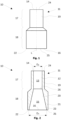
- Fig. 1 shows a nozzle 10 according to a preferred embodiment of the invention.
- the nozzle 10 serves to apply a viscous and curable material mixture as beads or beads of material.
- a two-component system is preferably used as the material mixture.
- the material beads are applied in layers.
- the nozzle 10 is thus used for 3D printing of components or component blanks.
- the Nozzle 10 is preferably used for the production of 3D-printed parts.
- nozzle 10 can be arranged on a mixing head of an industrial robot. Specifically, nozzle 10 can be fluidly connected to a mixing unit of the mixing head for supplying the two-component system. Nozzle 10 can be arranged directly on a rigid mixing body of the mixing unit.
- the nozzle 10 can be pushed onto one end of a plastic line, in particular a plastic tube.
- a plastic line in particular a plastic tube.
- the end of the plastic line is partially inserted into the nozzle 10 such that the nozzle 10 is firmly held at the hose end.
- the nozzle 10 has a base body 11 and a nozzle channel 12 formed in the base body 11.
- the nozzle channel 12 extends completely through the base body 11.
- the base body 11 has a central longitudinal axis L along which the nozzle channel 12 runs. The base body 11 will be discussed in detail later.
- FIG. 2 A longitudinal section through the nozzle 10 is shown, clearly showing the shape of the nozzle channel 12.
- the nozzle channel 12 comprises a first channel section 13 and a second channel section 15, which directly adjoins the first channel section 13.
- the first channel section 13 merges seamlessly into the second channel section 15 at a transition 26.
- the first channel section 13 has an inlet opening 14 with a diameter DE .
- the second channel section 15 has an outlet opening 16 with an outlet diameter DA .
- the outlet opening 16 is formed opposite the inlet opening 14. During application, the two-component system exits the nozzle 10 through the outlet opening 16.
- the nozzle channel 12 widens towards the outlet opening 16.
- the second channel section 15 widens starting from the first channel section 13 in such a way that the outlet diameter D A of the outlet opening 16 is larger than the diameter D E of the inlet opening 14.
- the Outlet opening 16 has a circular outlet contour which is larger than a circular inlet contour of the inlet opening 14.
- Fig. 2 It is shown that the flow cross-section of the nozzle channel 12 increases exclusively along its course, starting from the transition 26 to the outlet opening 16 of the second channel section 15.
- the second channel section 15 has a flow cross-section that continuously expands along the central longitudinal axis L.
- the flow cross-section expands in a circular manner. Other cross-sectional contours are possible.
- the second channel section 15 is conical.
- the second channel section 15 is formed by an inner cone 20 that is incorporated into the base body 11.
- the cylindrical first channel section 13 thus transitions into the conical second channel section 15 to transfer the two-component system.
- the first channel section 13 is cylindrical and has a constant diameter along its length.
- the constant diameter corresponds to the diameter DE of the inlet opening 14 of the first channel section 13.
- the first channel section 13 has a constant flow cross-section along its length.
- the first channel section 13 is formed by a bore.
- Fig. 2 further shows that the first channel section 13 and the second channel section 15 are designed to be free of undercuts in the flow direction of the nozzle channel 12. Specifically, this means that the nozzle channel 12, and in particular the second channel section 15, are designed to be free of dead spaces in the flow direction of the two-component system. This has the advantage that no part of the two-component system can deposit or settle during application, thus preventing clogging of the nozzle 10.
- the second channel section 15 is thus preferably designed to be step-free, in particular free of niches.
- the inner cone 20 of the second channel section 16 widens at an angle between 0° and 30°, in particular 5° and 20°, preferably substantially 15°, towards the outlet opening 16.
- the angle is spanned in a plane that is normal to the central longitudinal axis L, between the central longitudinal axis L and a surface 23 of the inner cone 20.
- the base body 11 comprises a first body region 17 comprising the first channel section 13, wherein the integrated first channel section forms a connection 19 for a supply device, in particular a hose, for supplying the two-component system.
- the base body 11 has a second body region 18 comprising the second channel section 15, the wall thickness 21 of which tapers towards the outlet opening 16.
- the base body 11 comprises a nozzle edge 22 at the outlet opening 16, towards which the inner surface 23 of the second channel section 15 or the inner cone 20 runs.
- the base body 11 is rotationally symmetrical. Other body shapes are possible.
- the second body region 18 extends radially beyond the first body region 17. In other words, the second body region 18 is radially larger than the first body region 17.
- the base body 11 preferably has a length along the central longitudinal axis L of 50 mm to 100 mm, in particular 60 mm to 90 mm, particularly preferably 70 mm to 80 mm. Other lengths are possible.
- the base body 11 comprises a first longitudinal end 24 and a second longitudinal end 25, which are arranged opposite one another in the longitudinal direction.
- the first longitudinal end 24 comprises the inlet opening 14 of the nozzle channel 12.
- the second longitudinal end 25 has the outlet opening 16 of the nozzle channel 12. The first longitudinal end 24 closes off the first body region 17, and the second longitudinal end 25 closes off the second body region 18.
- two material components are mixed to form a 2-component system and the 2-component system is fed to the inlet opening 14 of the nozzle channel 12 of the nozzle 10.
- the 2-component system then flows through the nozzle channel 12 without leaving any residue due to the undercut-free channel contour.
- a material bead with a specific width is formed, which is larger than the diameter D E of the inlet opening 14.
- Several material beads are then applied to one another to form a 3D-printed component or a 3D-printed blank.
- the wall thickness of the 3D-printed component or the 3D-printed blank essentially corresponds to the width of the successive applied material beads.
- milling is carried out to form the final outer contour of the component by milling off the component or blank contour created by 3D printing.
Landscapes
- Chemical & Material Sciences (AREA)
- Engineering & Computer Science (AREA)
- Materials Engineering (AREA)
- Manufacturing & Machinery (AREA)
- Physics & Mathematics (AREA)
- Mechanical Engineering (AREA)
- Optics & Photonics (AREA)
Priority Applications (2)
| Application Number | Priority Date | Filing Date | Title |
|---|---|---|---|
| EP23205692.9A EP4545276A1 (fr) | 2023-10-25 | 2023-10-25 | Buse pour un dispositif de construction par couches d'un composant, dispositif doté d'une telle buse et procédé de fabrication d'un composant |
| PCT/EP2024/080328 WO2025088184A1 (fr) | 2023-10-25 | 2024-10-25 | Buse pour dispositif de fabrication d'un composant en couches, dispositif comprenant ladite buse, et procédé de production d'un composant |
Applications Claiming Priority (1)
| Application Number | Priority Date | Filing Date | Title |
|---|---|---|---|
| EP23205692.9A EP4545276A1 (fr) | 2023-10-25 | 2023-10-25 | Buse pour un dispositif de construction par couches d'un composant, dispositif doté d'une telle buse et procédé de fabrication d'un composant |
Publications (1)
| Publication Number | Publication Date |
|---|---|
| EP4545276A1 true EP4545276A1 (fr) | 2025-04-30 |
Family
ID=88511301
Family Applications (1)
| Application Number | Title | Priority Date | Filing Date |
|---|---|---|---|
| EP23205692.9A Withdrawn EP4545276A1 (fr) | 2023-10-25 | 2023-10-25 | Buse pour un dispositif de construction par couches d'un composant, dispositif doté d'une telle buse et procédé de fabrication d'un composant |
Country Status (2)
| Country | Link |
|---|---|
| EP (1) | EP4545276A1 (fr) |
| WO (1) | WO2025088184A1 (fr) |
Citations (4)
| Publication number | Priority date | Publication date | Assignee | Title |
|---|---|---|---|---|
| DE202012001873U1 (de) | 2012-02-27 | 2012-04-02 | Udo Tartler | Vorrichtung zum Auftragen insbesondere von pastösem Kunststoff auf eine Fläche |
| EP3658355A1 (fr) | 2017-07-24 | 2020-06-03 | University of South Carolina | Ensemble buse d'un système d'impression 3d pour l'impression de pièces renforcées par des fibres |
| US20210094230A9 (en) * | 2016-11-04 | 2021-04-01 | Continuous Composites Inc. | System for additive manufacturing |
| CA2907492C (fr) * | 2013-03-22 | 2022-03-29 | Gregory Thomas Mark | Impression tridimensionnelle |
-
2023
- 2023-10-25 EP EP23205692.9A patent/EP4545276A1/fr not_active Withdrawn
-
2024
- 2024-10-25 WO PCT/EP2024/080328 patent/WO2025088184A1/fr active Pending
Patent Citations (4)
| Publication number | Priority date | Publication date | Assignee | Title |
|---|---|---|---|---|
| DE202012001873U1 (de) | 2012-02-27 | 2012-04-02 | Udo Tartler | Vorrichtung zum Auftragen insbesondere von pastösem Kunststoff auf eine Fläche |
| CA2907492C (fr) * | 2013-03-22 | 2022-03-29 | Gregory Thomas Mark | Impression tridimensionnelle |
| US20210094230A9 (en) * | 2016-11-04 | 2021-04-01 | Continuous Composites Inc. | System for additive manufacturing |
| EP3658355A1 (fr) | 2017-07-24 | 2020-06-03 | University of South Carolina | Ensemble buse d'un système d'impression 3d pour l'impression de pièces renforcées par des fibres |
Also Published As
| Publication number | Publication date |
|---|---|
| WO2025088184A1 (fr) | 2025-05-01 |
Similar Documents
| Publication | Publication Date | Title |
|---|---|---|
| EP0431681B1 (fr) | Procédé et outil d'extrusion pour la fabrication d'une ébauche pourvue d'alésages internes | |
| EP1042086B1 (fr) | Procede de production d'un outil de percage pour machines-outils | |
| EP4168225B1 (fr) | Procédé de production d'un composant comportant un système de canal de refroidissement | |
| EP0458774B2 (fr) | Lopin de métal dur ou céramique et méthode et outil pour la manufacture de ceux-ci | |
| DE102018202941B4 (de) | Verfahren zur Herstellung eines Rohlings aus Extrusionsmasse sowie Extruder | |
| DE102016012388A1 (de) | Verteilerplattenpaket für einen blaskopf einer blasfolienanlage, blaskopf, verfahren zum herstellen einer folie im blasfolienverfahren, verfahren zum umrüsten eines blaskopfes sowie blasfolienanlage | |
| WO2015166065A1 (fr) | Foret fabriqué à l'aide d'un procédé de frittage laser | |
| WO2021074340A1 (fr) | Technique d'extrusion pour former des préformes en matière plastique et technique de formation de tubes | |
| EP3609672B1 (fr) | Connecteur enfichable en matière plastique et procédé de fabrication associé | |
| DE102009060043B4 (de) | Vorrichtung zum Spritzgießen von Rohrteilen aus Kunststoff | |
| WO2025088184A1 (fr) | Buse pour dispositif de fabrication d'un composant en couches, dispositif comprenant ladite buse, et procédé de production d'un composant | |
| DE102018216149A1 (de) | Vorrichtung zur Beeinflussung des Volumenstroms von extrudiertem plastisch verformbaren Werkstoff | |
| DE102006042065A1 (de) | Verfahren und Vorrichtung zur Herstellung von bandförmigen Kunststoffvorformlingen | |
| DE102010023302A1 (de) | Wendelverteiler, Blaskopf, Blasfolienanlage, Verfahren zum Herstellen einer Blasfolie sowie Blasfolie | |
| DE10246726A1 (de) | Verfahren zur Herstellung einer Drosselklappe in einem durchgehenden Drosselklappenstutzen | |
| DE102017113891A1 (de) | Reduzierhülse sowie Schneidvorrichtung | |
| EP3684585B1 (fr) | Procédé et dispositif de fabrication d'un corps cylindrique circulaire constitué d'une matière plastique | |
| AT520657B1 (de) | Druckkopf für das schichtweise Aufbringen von Material | |
| DE102017212054B4 (de) | Verfahren zur Herstellung eines Schneidkopfes sowie Schneidkopf | |
| EP2483027B1 (fr) | Procédé de fabrication d'une denture intérieure | |
| DE19757827A1 (de) | Mehrschichtadapter für eine Extrusionsvorrichtung | |
| WO2019091926A1 (fr) | Distributeur annulaire pour une tête d'extrusion pour la fabrication d'une pièce moulée en forme de tuyau à partir d'un matériau thermoplastique | |
| DE102005037308B4 (de) | Entlüftetes, mit einem Werkstoff befüllbares Spritzwerkzeug | |
| EP3649068B1 (fr) | Axe de rouleau de convoyeur | |
| EP3666494A1 (fr) | Système de refroidissement de noyau pour un noyau de moulage d'un outil de moulage par injection |
Legal Events
| Date | Code | Title | Description |
|---|---|---|---|
| PUAI | Public reference made under article 153(3) epc to a published international application that has entered the european phase |
Free format text: ORIGINAL CODE: 0009012 |
|
| STAA | Information on the status of an ep patent application or granted ep patent |
Free format text: STATUS: THE APPLICATION HAS BEEN PUBLISHED |
|
| AK | Designated contracting states |
Kind code of ref document: A1 Designated state(s): AL AT BE BG CH CY CZ DE DK EE ES FI FR GB GR HR HU IE IS IT LI LT LU LV MC ME MK MT NL NO PL PT RO RS SE SI SK SM TR |
|
| STAA | Information on the status of an ep patent application or granted ep patent |
Free format text: STATUS: THE APPLICATION IS DEEMED TO BE WITHDRAWN |
|
| 18D | Application deemed to be withdrawn |
Effective date: 20251031 |