EP3666494A1 - Système de refroidissement de noyau pour un noyau de moulage d'un outil de moulage par injection - Google Patents
Système de refroidissement de noyau pour un noyau de moulage d'un outil de moulage par injection Download PDFInfo
- Publication number
- EP3666494A1 EP3666494A1 EP19214872.4A EP19214872A EP3666494A1 EP 3666494 A1 EP3666494 A1 EP 3666494A1 EP 19214872 A EP19214872 A EP 19214872A EP 3666494 A1 EP3666494 A1 EP 3666494A1
- Authority
- EP
- European Patent Office
- Prior art keywords
- cooling tube
- cooling
- core
- outlet
- inlet
- Prior art date
- Legal status (The legal status is an assumption and is not a legal conclusion. Google has not performed a legal analysis and makes no representation as to the accuracy of the status listed.)
- Withdrawn
Links
- 238000001816 cooling Methods 0.000 title claims abstract description 171
- 238000001746 injection moulding Methods 0.000 title claims abstract description 14
- 239000012530 fluid Substances 0.000 claims abstract description 48
- 239000004033 plastic Substances 0.000 claims abstract description 10
- 229920003023 plastic Polymers 0.000 claims abstract description 10
- 238000000034 method Methods 0.000 claims description 7
- 238000002347 injection Methods 0.000 claims description 5
- 239000007924 injection Substances 0.000 claims description 5
- 238000010146 3D printing Methods 0.000 claims description 4
- 239000012809 cooling fluid Substances 0.000 description 37
- 238000004519 manufacturing process Methods 0.000 description 6
- 239000000155 melt Substances 0.000 description 6
- 239000000047 product Substances 0.000 description 4
- 239000004952 Polyamide Substances 0.000 description 3
- XECAHXYUAAWDEL-UHFFFAOYSA-N acrylonitrile butadiene styrene Chemical compound C=CC=C.C=CC#N.C=CC1=CC=CC=C1 XECAHXYUAAWDEL-UHFFFAOYSA-N 0.000 description 3
- 229920000122 acrylonitrile butadiene styrene Polymers 0.000 description 3
- 239000004676 acrylonitrile butadiene styrene Substances 0.000 description 3
- 229920002647 polyamide Polymers 0.000 description 3
- 239000007795 chemical reaction product Substances 0.000 description 2
- 238000010276 construction Methods 0.000 description 2
- 239000000463 material Substances 0.000 description 2
- 239000004800 polyvinyl chloride Substances 0.000 description 2
- 238000004026 adhesive bonding Methods 0.000 description 1
- 239000002826 coolant Substances 0.000 description 1
- 239000000112 cooling gas Substances 0.000 description 1
- 239000000110 cooling liquid Substances 0.000 description 1
- 239000000498 cooling water Substances 0.000 description 1
- 238000006073 displacement reaction Methods 0.000 description 1
- 239000003292 glue Substances 0.000 description 1
- 238000010438 heat treatment Methods 0.000 description 1
- 238000009434 installation Methods 0.000 description 1
- 239000002245 particle Substances 0.000 description 1
- 229920000915 polyvinyl chloride Polymers 0.000 description 1
- 238000005476 soldering Methods 0.000 description 1
- XLYOFNOQVPJJNP-UHFFFAOYSA-N water Substances O XLYOFNOQVPJJNP-UHFFFAOYSA-N 0.000 description 1
- 238000003466 welding Methods 0.000 description 1
Images


Classifications
-
- B—PERFORMING OPERATIONS; TRANSPORTING
- B29—WORKING OF PLASTICS; WORKING OF SUBSTANCES IN A PLASTIC STATE IN GENERAL
- B29C—SHAPING OR JOINING OF PLASTICS; SHAPING OF MATERIAL IN A PLASTIC STATE, NOT OTHERWISE PROVIDED FOR; AFTER-TREATMENT OF THE SHAPED PRODUCTS, e.g. REPAIRING
- B29C45/00—Injection moulding, i.e. forcing the required volume of moulding material through a nozzle into a closed mould; Apparatus therefor
- B29C45/17—Component parts, details or accessories; Auxiliary operations
- B29C45/72—Heating or cooling
- B29C45/73—Heating or cooling of the mould
- B29C45/7312—Construction of heating or cooling fluid flow channels
-
- B—PERFORMING OPERATIONS; TRANSPORTING
- B29—WORKING OF PLASTICS; WORKING OF SUBSTANCES IN A PLASTIC STATE IN GENERAL
- B29C—SHAPING OR JOINING OF PLASTICS; SHAPING OF MATERIAL IN A PLASTIC STATE, NOT OTHERWISE PROVIDED FOR; AFTER-TREATMENT OF THE SHAPED PRODUCTS, e.g. REPAIRING
- B29C45/00—Injection moulding, i.e. forcing the required volume of moulding material through a nozzle into a closed mould; Apparatus therefor
- B29C45/17—Component parts, details or accessories; Auxiliary operations
- B29C45/26—Moulds
- B29C45/261—Moulds having tubular mould cavities
-
- B—PERFORMING OPERATIONS; TRANSPORTING
- B29—WORKING OF PLASTICS; WORKING OF SUBSTANCES IN A PLASTIC STATE IN GENERAL
- B29K—INDEXING SCHEME ASSOCIATED WITH SUBCLASSES B29B, B29C OR B29D, RELATING TO MOULDING MATERIALS OR TO MATERIALS FOR MOULDS, REINFORCEMENTS, FILLERS OR PREFORMED PARTS, e.g. INSERTS
- B29K2105/00—Condition, form or state of moulded material or of the material to be shaped
- B29K2105/25—Solid
- B29K2105/253—Preform
- B29K2105/258—Tubular
Definitions
- the present invention relates to a core cooling system for a mold core for injection molding plastic preforms, consisting of a mold core and a cooling tube.
- preforms are also referred to as preforms.
- the present invention is used in particular in the case of core cooling systems of injection molding tools which are suitable for the production of preforms, but can also be used in cooling systems of other tools.
- Injection molding tools can be used to manufacture a wide variety of products, and they are used in particular for the production of preforms from which finished end products are produced by further forming processes.
- a PET bottle is produced by inflating a preform previously produced by injection molding.
- Injection molding tools usually have a large number of cavities (molded containers), e.g. 96 cavities, and associated mold cores.
- the mold cores are inserted into the cavities to produce a preform.
- the cavity and mold core are designed and arranged in such a way that, after the mold core has been introduced into the cavity, a so-called mold space is formed between the inner surface of the cavity and the outer surface of the mold core, the shape of which corresponds to the desired shape of the preform.
- the mold space is limited on the outside by the cavity and on the inside by the mold core. Consequently, the outer contour of the preform corresponds to the inner contour of the cavity and the inner contour of the preform corresponds to the outer contour of the mandrel protruding into the cavity.
- the melt - usually plasticized plastic, e.g. PET, - injected under high pressure. As soon as the melt has cooled sufficiently and has thereby solidified sufficiently, the mold is opened and the solidified melt is removed from the cavity as a preform.
- the melt in the mold cavity must be cooled quickly and efficiently after injection.
- the preform is cooled by the mandrel, which also acts as a cooling pin.
- the mandrel is cooled with a core cooling system, which is usually based on a cooling fluid circuit.
- the mandrel is designed as a sleeve which is closed on one side and into which cooling fluid is continuously fed in and then out again.
- a core cooling system is composed at least of the mold core itself and a cooling tube through which the necessary cooling fluid (cooling liquid or cooling gas) is conducted into the interior of the mold core.
- Such a core cooling system is from the EP 1019 234 B1 known.
- cooling fluid is conducted via the cooling tube to the tip of the mandrel, emerges from the cooling tube at this point and flows out again through the gap between the outer surface of the cooling tube and the inner surface of the mandrel.
- the channel which is delimited by the inner surface of the cooling tube is referred to below as the fluid channel or also as the first fluid channel and the channel which extends as a gap between the inner surface of the mandrel and the outer surface of the cooling tube is referred to as the core cooling channel.
- the entire area in which cooling fluid can flow, i.e. H. the combination of the first fluid channel and the core cooling channel is referred to below as the cooling line.
- cooling pipe Since the cooling pipe is usually acted upon by cooling water, the cooling pipe can move axially within the mold core. The cooling pipe is thus pressed forward by the water pressure in the direction of the tip of the mandrel. Cooling tubes are therefore already known which have protrusions at their tips. These projections are intended to prevent the cooling line from closing when the cooling tube moves along the longitudinal axis in the direction of the tip of the mandrel.
- centering elements were used, which are pulled over the outer surface of the cooling tube in order to position the cooling tube in the center of the mandrel.
- a support of the cooling tube in order to prevent the cooling tube from moving forward within the mold core is, however, not connected to this.
- Uniform cooling of the mandrel is generally desirable.
- the mold core would best have a constant wall thickness and the outer surface of the cooling tube should ensure that the cooling channel which forms between the outer surface of the cooling tube and the inner contour of the mold core also has an essentially constant thickness.
- Such a near-contour design of the cooling tube is desirable, but not easy and inexpensive to manufacture. Every end product, and consequently every variant of PET bottles, is made from a preform tailored precisely to this product. Therefore, the preforms of the products differ from each other just as the products differ from each other.
- the mold cores used differ and consequently also the inner contours of the mold cores.
- a separate variant of cooling tubes must be produced for each variant of the mandrel in order to provide a near-contour core cooling duct. This is usually associated with a lot of effort and costs.
- the support of the cooling tube via the projections is also not very stable and is associated with increased wear, since the cooling tube is supported only at the tip of the cooling tube via the projections. Since the projections do not have an outer contour corresponding to the inner contour of the mandrel, there is also increased friction between the inner surface of the mandrel and the projections, and thus increased wear of the projections.
- the objects on which the present invention is based are to provide a core cooling system or a cooling tube, by means of which a stable support of the cooling tube, a simple and cost-effective design of the core cooling duct as close as possible and an improved, more homogeneous cooling of the mold core is made possible.
- At least one of these objects is achieved by a cooling tube according to claim 1 or a core cooling system according to claim 11.
- the cooling tube according to the invention is provided for a mold core of an injection molding tool for the injection molding of plastic preforms.
- the cooling tube extends along a longitudinal axis from a rear end to a front end and has an outer surface, wherein a first fluid channel is provided which extends from a first inlet to a first outlet, the first inlet being arranged closer to the rear end is than the first outlet, the cooling tube having a second inlet and a second outlet, which are connected to one another via a second fluid channel, the second inlet being arranged closer to the rear end than the second outlet and the first outlet being arranged closer to the rear end is as the second outlet.
- both the supply channel and the discharge channel are guided in at least one section inside the cooling tube, so that the cooling tube can be supported on the outer surface in this section without impairing the cooling fluid flow.
- the cooling tube has a front section which comprises the front end and a rear section which comprises the rear end, the first fluid channel being arranged in the front and rear section and the second fluid channel only is arranged in the rear section, the rear section preferably having a larger cross-sectional area than the front section.
- the cooling tube can thus be supported in the rear section.
- the core cooling channel thus runs in the gap between the inner surface of the mandrel and the outer surface of the cooling tube.
- the first and the second inlet are positioned such that when the cooling tube is rotated through 180 ° about its longitudinal axis, the first and the second inlet swap positions.
- the cooling tube can be used in two different installation situations, namely in two positions rotated relative to one another by 180 ° about the longitudinal axis.
- the first inlet is connected to a cooling fluid supply and the second inlet is connected to a cooling fluid discharge.
- the cooling fluid is thus fed into the cooling tube via the first inlet, leaves the cooling tube at the first outlet, flows back on the outer surface of the cooling tube from the front end towards the rear end, re-enters the cooling tube into the second outlet and finally via the second Entry into the cooling fluid drain.
- the cooling fluid flows in the opposite direction.
- the second inlet is now connected to the cooling fluid supply and the first inlet is connected to a cooling fluid discharge.
- the cooling fluid supply is thus fed into the cooling tube via the second inlet, leaves the cooling tube at the second outlet, flows on the outer surface of the cooling tube from the rear end towards the front end, re-enters the cooling tube into the first outlet and finally via the first inlet into the cooling fluid drain.
- first inlet and / or the second inlet are arranged in the end face of the cooling tube at the rear end. This arrangement enables easy supply and removal of coolant.
- the second outlet is arranged in the lateral surface, the first outlet preferably being arranged in the end surface of the cooling tube at the front end. This arrangement has proven to be particularly effective for uniform cooling of the mandrel.
- At least one centering element projecting beyond the outer surface is provided on the outer surface of the cooling tube, the centering element preferably extending helically in the longitudinal direction around the outer surface of the cooling tube.
- the centering element is intended to come into contact with a mandrel at least when the cooling tube is not arranged exactly in the center of the mandrel.
- the centering element is not used to support the cooling tube in the mandrel.
- At least two centering elements are provided, so that when the cooling tube is inserted into a mold core whose inner diameter approximately corresponds to the outer diameter of the centering elements, third fluid channels are formed between the centering elements, the outer surface of the cooling tube and the inner surface of the mold core.
- the second outlet preferably connects the second fluid channel to a third fluid channel, it being best for each third fluid channel to be assigned its own second outlet, which is connected to the second fluid channel.
- centering elements thus also serve for the targeted guidance of the fluid by guiding the fluid into certain paths, which are called third fluid channels here.
- centering elements insofar as they are designed such that they are in an assembled state of the mandrel and the cooling tube in contact with the core inner surface or the outer surface of the cooling tube, for stable mounting of the Cooling tube inside the mandrel.
- the centering elements consequently support the cooling tube in directions perpendicular to the longitudinal axis and center it within the mandrel, so that lateral displacement of the cooling tube within the mandrel is prevented.
- the helical design of the support elements has the advantage that the cooling tube is supported within the mold core in a much more stable manner during operation and the flow of the cooling fluid. This can be explained by the fact that without the cooling fluid being guided in channels by means of centering elements, the smallest pressure or speed differences are sufficient to destabilize the cooling tube during operation or even to set it in vibration. Any pressure and speed differences that occur are compensated for by the helical guidance of the cooling fluid.
- the melt may be hotter on one side of the mandrel than on the other. Due to the helical guidance of the cooling fluid, almost all particles of the cooling fluid are involved in the cooling of the hot side, which would not be the case with a linear guidance. This makes cooling more efficient, which enables shorter cycle times.
- the cooling tube is produced by a 3D printing process.
- the advantage of the 3D printing process in this context is that any arrangement of the fluid channels and the centering element - however complex it may be - can be easily manufactured.
- the cooling tube is formed in one piece.
- a one-piece design is advantageous because there are no seams or glue points that are usually exposed to increased wear. Therefore, a longer life of the cooling tube is guaranteed by a one-piece design.
- one-piece construction is understood to be one-piece construction and from the same material. Elements which are connected to one another for example by means of gluing, soldering or welding are not formed in one piece with the respective element or the respective surface in the sense of the present invention.
- Such a one-piece design is advantageous because in this case the cooling fluid does not have to flow around additional flow obstacles, as would be the case, for example, with a separate design
- the cooling tube is made of plastic and preferably of polyamide (PA) or acrylonitrile-butadiene-styrene copolymers (ABS).
- PA polyamide
- ABS acrylonitrile-butadiene-styrene copolymers
- PVC polyvinyl chloride
- Plastic has the advantages as a material that it is inexpensive on the one hand and that it can easily be shaped into the desired shape on the other.
- a cooling pipe with high quality and any shape can be made of PA, ABS or PVC.
- the present invention also includes a core cooling system of an injection molding tool for injection molding plastic preforms with a mold core.
- the mandrel has the shape of a hollow sleeve closed on one side with a longitudinal axis, an outer core surface and an inner core surface.
- the core cooling system has a cooling tube of the type described. The cooling tube is arranged in the mold core in such a way that a third fluid channel adjoining the first fluid channel is formed by the gap remaining between the outer surface of the cooling tube and the core inner surface.
- the distance between the inner core surface and the outer surface of the cooling tube along the core cooling channel is essentially constant. This essentially results in a uniform velocity of the flow within the gap between the core inner surface and the outer surface of the cooling tube (in the third fluid channel), which causes homogeneous cooling of the preform.
- the maximum distance between the outer surface of the cooling tube and the core inner surface of the mandrel and thus the maximum extent of the third fluid channel in the radial direction is 3 mm. For some applications, a maximum distance of 2 mm between the outer surface of the cooling tube and the inner core surface of the mold core has proven to be advantageous.
- FIG. 1-3 A perspective view, a sectional view and a bottom view of an embodiment of the cooling tube 1 according to the invention are shown.
- the cooling pipe has a front section 3, which comprises the front end 4 of the cooling pipe 1, and a rear section 2, which comprises the rear end 5 of the cooling pipe 1.
- a first fluid channel 6 extends between the rear end 5 and the front end 4 and is delimited by a first inlet 7 and a first outlet 8.
- a second fluid channel 9 is provided, which extends from the second inlet 10 to the second outlet 11.
- a plurality of second outlets 11 can also be provided, all of which are connected to the second fluid channel 9.
- the rear section 2 has a larger outer diameter than the front section 3. Both the first fluid channel 6 and the second fluid channel 9 are arranged in the rear section 2, while only the first fluid channel 6 is arranged in the front section 3.
- a plurality of centering elements 12 are arranged on the outer surface of the cooling tube 1 and extend helically in the direction of the longitudinal axis of the cooling tube 1 over the front section 3 of the cooling tube 1.
- the second outlet 8 is arranged on the one hand in the front end face of the cooling tube 1, but on the other hand has recesses 13 in the outer surface of the cooling tube 1.
- Each recess 13 is arranged between two adjacent centering elements 12. Every second outlet 11 is also arranged between two adjacent centering elements 12.
- a flange 14 is provided which has a support surface 15 which is inclined with respect to the longitudinal axis of the cooling tube 1.
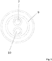
- FIG 3 a bottom view of the rear end 5 of the cooling tube 1 is shown.
- the first inlet 7 and the second inlet 10 can be seen.
- the two inlets 7, 10 are arranged in such a way that they swap positions by rotating through 180 ° about the longitudinal axis. Since, as will be explained in more detail below, cooling fluid is supplied via one of the two inlets 7, 10 and cooling fluid is discharged via the other of the two inlets 7, 10, the direction of flow of the cooling fluid within the core cooling system can be reversed in that the cooling tube 1 is rotated by 180 ° about its longitudinal axis.
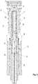
- FIG 4 a sectional view of a core cooling system according to the invention is shown. It can be seen that the cooling tube 1 is inserted into a mandrel 16. The centering elements 12 abut the inner surface of the mandrel 16, so that a third fluid channel 17 is formed between two centering elements 12, the outer surface of the cooling tube 1 and the inner surface of the mandrel 16, which extends helically around the cooling tube 1. Since 3 centering elements 12 are provided in the embodiment shown, a third fluid channel is formed in each case between two adjacent centering elements 12.
- cooling fluid can be conducted into the first fluid channel 6 via a cooling fluid supply 18.
- the cooling fluid leaves the cooling tube at the front end via the first outlet 8 and is then transported via the helical third fluid channels 17 along the outer surface of the cooling tube 1 in the direction of the rear end 5 until the cooling fluid enters the second fluid channel 7 via the second outlet and finally leaves the cooling system via the second inlet into the cooling fluid return 19.
- the cooling fluid flow direction within the mandrel 16 can be reversed in a simple manner if the cooling tube 1 is rotated through 180 ° about its longitudinal axis, so that the cooling fluid supply 18 is then connected to the second fluid channel 7 and the cooling fluid return 19 is connected to the first fluid channel 6.
- the mold core 16 has at its rear end a section with an enlarged inner diameter in which the flange 14 of the cooling tube 1 comes to rest.
- the neck jaws 20, 21, the cavity 24 and the bottom insert 23 are also shown. These elements are arranged relative to the mold core 16 in such a way that there is a mold space between them in which the preform 22 is arranged. Furthermore, a support element 25 can be seen with which the mandrel 16 is held.
Landscapes
- Physics & Mathematics (AREA)
- Fluid Mechanics (AREA)
- Engineering & Computer Science (AREA)
- Manufacturing & Machinery (AREA)
- Mechanical Engineering (AREA)
- Moulds For Moulding Plastics Or The Like (AREA)
Applications Claiming Priority (1)
| Application Number | Priority Date | Filing Date | Title |
|---|---|---|---|
| DE102018132339.5A DE102018132339A1 (de) | 2018-12-14 | 2018-12-14 | Kernkühlsystem für einen Formkern eines Spritzgießwerkzeuges |
Publications (1)
| Publication Number | Publication Date |
|---|---|
| EP3666494A1 true EP3666494A1 (fr) | 2020-06-17 |
Family
ID=68848073
Family Applications (1)
| Application Number | Title | Priority Date | Filing Date |
|---|---|---|---|
| EP19214872.4A Withdrawn EP3666494A1 (fr) | 2018-12-14 | 2019-12-10 | Système de refroidissement de noyau pour un noyau de moulage d'un outil de moulage par injection |
Country Status (2)
| Country | Link |
|---|---|
| EP (1) | EP3666494A1 (fr) |
| DE (1) | DE102018132339A1 (fr) |
Citations (4)
| Publication number | Priority date | Publication date | Assignee | Title |
|---|---|---|---|---|
| US4238106A (en) * | 1979-12-03 | 1980-12-09 | Owens-Illinois, Inc. | Core pin cooling for high speed injection molding apparatus |
| EP1019234B1 (fr) | 1997-04-16 | 2007-08-01 | Husky Injection Molding Systems Ltd. | Procede et appareil de cristallisation partielle d'articles en plastique amorphe |
| DE102013100277A1 (de) * | 2013-01-11 | 2014-07-17 | Friedrich Glas | Formkern, Formeinsatz und Formwerkzeug zum Herstellen von Formteilen |
| US20160214280A1 (en) * | 2013-09-20 | 2016-07-28 | Husky Injection Molding Systems Ltd. | Mold component |
Family Cites Families (3)
| Publication number | Priority date | Publication date | Assignee | Title |
|---|---|---|---|---|
| JP3345196B2 (ja) * | 1994-11-09 | 2002-11-18 | 株式会社吉野工業所 | 射出成形金型のコア冷却用スパイラルパイプとその製造方法 |
| JPH1142644A (ja) * | 1997-07-28 | 1999-02-16 | Saeki M Bii S:Kk | バッフルプレート |
| CA2255798C (fr) * | 1998-12-07 | 2008-06-17 | Jobst Ulrich Gellert | Noyau de refroidissement d'equipement de moulage par injection a rainures helicoidales |
-
2018
- 2018-12-14 DE DE102018132339.5A patent/DE102018132339A1/de not_active Withdrawn
-
2019
- 2019-12-10 EP EP19214872.4A patent/EP3666494A1/fr not_active Withdrawn
Patent Citations (4)
| Publication number | Priority date | Publication date | Assignee | Title |
|---|---|---|---|---|
| US4238106A (en) * | 1979-12-03 | 1980-12-09 | Owens-Illinois, Inc. | Core pin cooling for high speed injection molding apparatus |
| EP1019234B1 (fr) | 1997-04-16 | 2007-08-01 | Husky Injection Molding Systems Ltd. | Procede et appareil de cristallisation partielle d'articles en plastique amorphe |
| DE102013100277A1 (de) * | 2013-01-11 | 2014-07-17 | Friedrich Glas | Formkern, Formeinsatz und Formwerkzeug zum Herstellen von Formteilen |
| US20160214280A1 (en) * | 2013-09-20 | 2016-07-28 | Husky Injection Molding Systems Ltd. | Mold component |
Also Published As
| Publication number | Publication date |
|---|---|
| DE102018132339A1 (de) | 2020-06-18 |
Similar Documents
| Publication | Publication Date | Title |
|---|---|---|
| EP0326584B2 (fr) | Procede et dispositif de production de corps creux et volumineux en plastique a parois stratifiees | |
| EP0486636B1 (fr) | Tete d'accumulation pour machines de moulage par soufflage | |
| EP3666493B1 (fr) | Système de refroidissement pour un noyau de moule d'un outil de moulage par injection | |
| EP4010166B1 (fr) | Distributeur de matière fondue | |
| EP2032329B1 (fr) | Cavité de moule avec canal de refroidissement en forme de méandre | |
| DE202019105683U1 (de) | Extrusionstechnik zur Bildung von Kunststoff-Vorformlingen und Profilierungstechnik | |
| EP3186063B1 (fr) | Système de traitement ultérieur de préformes fabriquées par moulage par injection | |
| EP1687127B1 (fr) | Structure d'une cavité de moule | |
| EP1979151B1 (fr) | Refroidissement de goulot amélioré | |
| DE10024625B4 (de) | Formnest für die Kunststoffverarbeitung | |
| WO2005108044A1 (fr) | Outil de moulage par injection | |
| DE102016112421A1 (de) | Corrugator, Extrusionsanlage sowie Verfahren | |
| EP3666494A1 (fr) | Système de refroidissement de noyau pour un noyau de moulage d'un outil de moulage par injection | |
| DE102005059130B4 (de) | Vorrichtung zum Spritzgießen von Formteilen | |
| DE202019105681U1 (de) | Extrusionstechnik zur Bildung von Kunststoff-Vorformlingen und Schlauchbildungstechnik | |
| DE102021003023B3 (de) | Formgebungswerkzeug und Verfahren zur Herstellung von Mehrlumenschläuchen | |
| DE202019105685U1 (de) | Extrusionstechnik zur Bildung von Kunststoff-Vorformlingen und Drosseltechnik | |
| DE4010404A1 (de) | Extrudiervorrichtung | |
| DE102024131951A1 (de) | Reinigung eines Spritzgießwerkzeuges | |
| EP4729270A1 (fr) | Nettoyage d'un outil de moulage par injection | |
| EP4545276A1 (fr) | Buse pour un dispositif de construction par couches d'un composant, dispositif doté d'une telle buse et procédé de fabrication d'un composant | |
| EP3153296A1 (fr) | Tête de pulvérisation pour un dispositif de fabrication d'un tuyau composite | |
| EP4279246A1 (fr) | Dispositif de micro-injection | |
| DE202019105678U1 (de) | Extrusionstechnik zur Bildung von Kunststoff-Vorformlingen und Schmelze-Aufnahmetechnik | |
| DE102008015436A1 (de) | Verfahren zur Herstellung thermoplastischer Hohlkörper |
Legal Events
| Date | Code | Title | Description |
|---|---|---|---|
| PUAI | Public reference made under article 153(3) epc to a published international application that has entered the european phase |
Free format text: ORIGINAL CODE: 0009012 |
|
| STAA | Information on the status of an ep patent application or granted ep patent |
Free format text: STATUS: THE APPLICATION HAS BEEN PUBLISHED |
|
| AK | Designated contracting states |
Kind code of ref document: A1 Designated state(s): AL AT BE BG CH CY CZ DE DK EE ES FI FR GB GR HR HU IE IS IT LI LT LU LV MC MK MT NL NO PL PT RO RS SE SI SK SM TR |
|
| AX | Request for extension of the european patent |
Extension state: BA ME |
|
| STAA | Information on the status of an ep patent application or granted ep patent |
Free format text: STATUS: REQUEST FOR EXAMINATION WAS MADE |
|
| 17P | Request for examination filed |
Effective date: 20201217 |
|
| RBV | Designated contracting states (corrected) |
Designated state(s): AL AT BE BG CH CY CZ DE DK EE ES FI FR GB GR HR HU IE IS IT LI LT LU LV MC MK MT NL NO PL PT RO RS SE SI SK SM TR |
|
| STAA | Information on the status of an ep patent application or granted ep patent |
Free format text: STATUS: EXAMINATION IS IN PROGRESS |
|
| 17Q | First examination report despatched |
Effective date: 20210428 |
|
| STAA | Information on the status of an ep patent application or granted ep patent |
Free format text: STATUS: THE APPLICATION IS DEEMED TO BE WITHDRAWN |
|
| 18D | Application deemed to be withdrawn |
Effective date: 20221018 |