EP4545369A1 - Ensemble valves de protection à circuits multiples et unité de traitement d'air - Google Patents
Ensemble valves de protection à circuits multiples et unité de traitement d'air Download PDFInfo
- Publication number
- EP4545369A1 EP4545369A1 EP23206058.2A EP23206058A EP4545369A1 EP 4545369 A1 EP4545369 A1 EP 4545369A1 EP 23206058 A EP23206058 A EP 23206058A EP 4545369 A1 EP4545369 A1 EP 4545369A1
- Authority
- EP
- European Patent Office
- Prior art keywords
- extension
- main
- housing
- circuit protection
- outlet
- Prior art date
- Legal status (The legal status is an assumption and is not a legal conclusion. Google has not performed a legal analysis and makes no representation as to the accuracy of the status listed.)
- Granted
Links
Images

Classifications
-
- F—MECHANICAL ENGINEERING; LIGHTING; HEATING; WEAPONS; BLASTING
- F17—STORING OR DISTRIBUTING GASES OR LIQUIDS
- F17D—PIPE-LINE SYSTEMS; PIPE-LINES
- F17D3/00—Arrangements for supervising or controlling working operations
- F17D3/01—Arrangements for supervising or controlling working operations for controlling, signalling, or supervising the conveyance of a product
-
- B—PERFORMING OPERATIONS; TRANSPORTING
- B60—VEHICLES IN GENERAL
- B60T—VEHICLE BRAKE CONTROL SYSTEMS OR PARTS THEREOF; BRAKE CONTROL SYSTEMS OR PARTS THEREOF, IN GENERAL; ARRANGEMENT OF BRAKING ELEMENTS ON VEHICLES IN GENERAL; PORTABLE DEVICES FOR PREVENTING UNWANTED MOVEMENT OF VEHICLES; VEHICLE MODIFICATIONS TO FACILITATE COOLING OF BRAKES
- B60T17/00—Component parts, details, or accessories of power brake systems not covered by groups B60T8/00, B60T13/00 or B60T15/00, or presenting other characteristic features
- B60T17/04—Arrangements of piping, valves in the piping, e.g. cut-off valves, couplings or air hoses
-
- B—PERFORMING OPERATIONS; TRANSPORTING
- B60—VEHICLES IN GENERAL
- B60G—VEHICLE SUSPENSION ARRANGEMENTS
- B60G17/00—Resilient suspensions having means for adjusting the spring or vibration-damper characteristics, for regulating the distance between a supporting surface and a sprung part of vehicle or for locking suspension during use to meet varying vehicular or surface conditions, e.g. due to speed or load
- B60G17/02—Spring characteristics, e.g. mechanical springs and mechanical adjusting means
- B60G17/04—Spring characteristics, e.g. mechanical springs and mechanical adjusting means fluid spring characteristics
- B60G17/052—Pneumatic spring characteristics
-
- B—PERFORMING OPERATIONS; TRANSPORTING
- B60—VEHICLES IN GENERAL
- B60T—VEHICLE BRAKE CONTROL SYSTEMS OR PARTS THEREOF; BRAKE CONTROL SYSTEMS OR PARTS THEREOF, IN GENERAL; ARRANGEMENT OF BRAKING ELEMENTS ON VEHICLES IN GENERAL; PORTABLE DEVICES FOR PREVENTING UNWANTED MOVEMENT OF VEHICLES; VEHICLE MODIFICATIONS TO FACILITATE COOLING OF BRAKES
- B60T13/00—Transmitting braking action from initiating means to ultimate brake actuator with power assistance or drive; Brake systems incorporating such transmitting means, e.g. air-pressure brake systems
- B60T13/10—Transmitting braking action from initiating means to ultimate brake actuator with power assistance or drive; Brake systems incorporating such transmitting means, e.g. air-pressure brake systems with fluid assistance, drive, or release
- B60T13/24—Transmitting braking action from initiating means to ultimate brake actuator with power assistance or drive; Brake systems incorporating such transmitting means, e.g. air-pressure brake systems with fluid assistance, drive, or release the fluid being gaseous
- B60T13/26—Compressed-air systems
-
- B—PERFORMING OPERATIONS; TRANSPORTING
- B60—VEHICLES IN GENERAL
- B60T—VEHICLE BRAKE CONTROL SYSTEMS OR PARTS THEREOF; BRAKE CONTROL SYSTEMS OR PARTS THEREOF, IN GENERAL; ARRANGEMENT OF BRAKING ELEMENTS ON VEHICLES IN GENERAL; PORTABLE DEVICES FOR PREVENTING UNWANTED MOVEMENT OF VEHICLES; VEHICLE MODIFICATIONS TO FACILITATE COOLING OF BRAKES
- B60T13/00—Transmitting braking action from initiating means to ultimate brake actuator with power assistance or drive; Brake systems incorporating such transmitting means, e.g. air-pressure brake systems
- B60T13/10—Transmitting braking action from initiating means to ultimate brake actuator with power assistance or drive; Brake systems incorporating such transmitting means, e.g. air-pressure brake systems with fluid assistance, drive, or release
- B60T13/66—Electrical control in fluid-pressure brake systems
- B60T13/68—Electrical control in fluid-pressure brake systems by electrically-controlled valves
- B60T13/683—Electrical control in fluid-pressure brake systems by electrically-controlled valves in pneumatic systems or parts thereof
-
- B—PERFORMING OPERATIONS; TRANSPORTING
- B60—VEHICLES IN GENERAL
- B60T—VEHICLE BRAKE CONTROL SYSTEMS OR PARTS THEREOF; BRAKE CONTROL SYSTEMS OR PARTS THEREOF, IN GENERAL; ARRANGEMENT OF BRAKING ELEMENTS ON VEHICLES IN GENERAL; PORTABLE DEVICES FOR PREVENTING UNWANTED MOVEMENT OF VEHICLES; VEHICLE MODIFICATIONS TO FACILITATE COOLING OF BRAKES
- B60T17/00—Component parts, details, or accessories of power brake systems not covered by groups B60T8/00, B60T13/00 or B60T15/00, or presenting other characteristic features
- B60T17/002—Air treatment devices
-
- B—PERFORMING OPERATIONS; TRANSPORTING
- B60—VEHICLES IN GENERAL
- B60T—VEHICLE BRAKE CONTROL SYSTEMS OR PARTS THEREOF; BRAKE CONTROL SYSTEMS OR PARTS THEREOF, IN GENERAL; ARRANGEMENT OF BRAKING ELEMENTS ON VEHICLES IN GENERAL; PORTABLE DEVICES FOR PREVENTING UNWANTED MOVEMENT OF VEHICLES; VEHICLE MODIFICATIONS TO FACILITATE COOLING OF BRAKES
- B60T17/00—Component parts, details, or accessories of power brake systems not covered by groups B60T8/00, B60T13/00 or B60T15/00, or presenting other characteristic features
- B60T17/18—Safety devices; Monitoring
-
- F—MECHANICAL ENGINEERING; LIGHTING; HEATING; WEAPONS; BLASTING
- F16—ENGINEERING ELEMENTS AND UNITS; GENERAL MEASURES FOR PRODUCING AND MAINTAINING EFFECTIVE FUNCTIONING OF MACHINES OR INSTALLATIONS; THERMAL INSULATION IN GENERAL
- F16K—VALVES; TAPS; COCKS; ACTUATING-FLOATS; DEVICES FOR VENTING OR AERATING
- F16K11/00—Multiple-way valves, e.g. mixing valves; Pipe fittings incorporating such valves
- F16K11/10—Multiple-way valves, e.g. mixing valves; Pipe fittings incorporating such valves with two or more closure members not moving as a unit
- F16K11/20—Multiple-way valves, e.g. mixing valves; Pipe fittings incorporating such valves with two or more closure members not moving as a unit operated by separate actuating members
- F16K11/22—Multiple-way valves, e.g. mixing valves; Pipe fittings incorporating such valves with two or more closure members not moving as a unit operated by separate actuating members with an actuating member for each valve, e.g. interconnected to form multiple-way valves
-
- F—MECHANICAL ENGINEERING; LIGHTING; HEATING; WEAPONS; BLASTING
- F17—STORING OR DISTRIBUTING GASES OR LIQUIDS
- F17D—PIPE-LINE SYSTEMS; PIPE-LINES
- F17D1/00—Pipe-line systems
- F17D1/02—Pipe-line systems for gases or vapours
- F17D1/04—Pipe-line systems for gases or vapours for distribution of gas
-
- B—PERFORMING OPERATIONS; TRANSPORTING
- B62—LAND VEHICLES FOR TRAVELLING OTHERWISE THAN ON RAILS
- B62D—MOTOR VEHICLES; TRAILERS
- B62D5/00—Power-assisted or power-driven steering
- B62D5/06—Power-assisted or power-driven steering fluid, i.e. using a pressurised fluid for most or all the force required for steering a vehicle
- B62D5/062—Details, component parts
Definitions
- the invention generally relates to a multi circuit protection valve assembly for a pressurized air system, in particular a pneumatic supply system of an air processing unit of a commercial vehicle, and an air processing unit comprising the same.
- Electropneumatic systems in commercial vehicles generally comprise a compressor, an air processing unit for providing drying and filtering the compressed air delivered by the compressor, a multi-circuit protection valve assembly for distributing the dried and filtered compressed air to consumer circuits, simultaneously separating the consumer circuits from each other.
- the consumer circuits include, in particular, pneumatic brake circuits, air suspension systems, and the like.
- the air processing unit generally comprises one or more desiccant air dryer cartridges filled with moisture-adsorbing materials like granulate.
- the compressed air is dried or de-moisturized in a drying mode, and the dried compressed air is then supplied to the multi-circuit protection valve assembly that distributes it to the subsequent consumer circuits.
- the air dryer cartridge can also be regenerated or purged in a regeneration mode, in which air flows in the reverse direction through the air dryer cartridges to a venting outlet.
- the multi-circuit protection valve assembly generally comprises several air circuits in which the compressed air is distributed, wherein the compressed air is received via an air inlet and is then supplied to several main outlets that are each coupled to a certain consumer circuit.
- the compressed air is distributed via several main supply lines, each being flow-connected or flow-connectable to the air inlet and each being flow-connected or flow-connectable to at least one of the main outlets.
- main overflow valves or check valves are located in each of the main supply lines for protecting the main outlet that is flow-connected or flow-connectable to the respective main supply line containing this main overflow valve. Thereby, the main overflow valves prevent air from escaping from all of the consumer circuits in case of a pressure loss in one of the consumer circuits.
- the main overflow valve or check valve is in its closed position as long as the air pressure in the air inlet is lower than an opening pressure.
- the pass-through position of the respective main overflow valve or check valve is preferably set once the air pressure of the compressed air in the air inlet is exceeding the opening pressure. In case of a pressure loss in one of the consumer circuits, the closed position is automatically set.
- an extension part can be provided, having an extension inlet for receiving compressed air, at least one extension outlet for discharging the received compressed air to a consumer circuit that is coupled to the respective extension outlet, an extension line being flow-connected or flow-connectable to said extension inlet and to the at least one extension outlet, and an extension overflow valve being located in the extension line for protecting the at least one extension outlet flow-connected or flow-connectable to the extension line containing the extension overflow valve.
- Each of these extending elements is attached or integrated into an extension housing, wherein the extension housing is detachably fixed to the main housing such that the extension inlet is flow-connected to an auxiliary outlet in the main housing, wherein the auxiliary outlet is flow-connected or flow-connectable to said air inlet in the main housing.
- the extension part or the extension housing is directly screwed to the main housing via screws each piercing through the extension housing and the main housing.
- the housings are positioned to each other such that the extension inlet is coaxially overlapping the auxiliary outlet, ensuring a flow-connection.
- Such a multi-circuit protection valve assembly or air processing unit already having several protected circuits and ports is a very compact device having a specific or predetermined design that results in a specific construction of the main housing.
- extending the device for providing further extension ports or extension outlets that are protected by further extension overflow valves is not always possible as the dimension or design are restricted in some way.
- the multi-circuit protection valve assembly is characterized in that, the extension housing is detachably fixed to the main housing by a hollow screw or banjo bolt having a cavity inside its shaft, wherein the hollow screw passes through the extension housing and is screwed directly into the auxiliary outlet
- the multi-circuit protection valve assembly or air processing unit can be easily expanded by adding an extension part having at least one, preferably at least two or more protected extension ports or extension outlets, wherein the fixation means for fixing the extension part or the extension housing to the main housing, i.e., the hollow screw, at the same time provides an air channel or cavity for deliberately guiding the compressed air to the additional extension overflow valve prior to reaching the respective extension outlet.
- the hollow screw advantageously fulfils a dual function, i.e., the fixation of the extension part and securely conveying the compressed air at the interface between the main housing and the extension housing.
- the coaxial positioning or overlapping of the extension inlet and the auxiliary outlet is automatically ensured.
- a space-saving and secure expansion of functionality is provided, wherein the auxiliary outlet that is not necessarily protected by an overflow valve inside the main housing, is extended in functionality by providing at least one, preferably at least two additional protected ports.
- the invention also relates to an air processing unit comprising the claimed multi-circuit protection valve assembly, and an air supply unit having a compressor port for connecting a compressor providing compressed air, an air dryer cartridge for drying and filtering the received compressed air, operating valves (regeneration valve, purging valve, compressor valve) for setting operating phases of the air supply unit (regeneration, drying, etc.), wherein the air supply unit is connected to the air inlet of the multi-circuit protection valve assembly. Further, the air supply unit is at least partially attached to or integrated into the main housing for providing a compact unit.
- the extension housing comprises a coupling part having an inner chamber with a first opening at a first terminal end, the first terminal end forming the extension inlet, wherein the hollow screw extends through said inner chamber and an end region of the hollow screw protrudes out of the first opening of the inner chamber, wherein the end region comprises an external thread being screwed into the auxiliary outlet for clamping the extension housing to the main housing via the hollow screw.
- the threaded end region of the hollow screw comprises an axial opening that transitions into the cavity for receiving compressed air from the auxiliary outlet.
- an easy way of guiding the compressed air from the auxiliary outlet into the cavity of the hollow screw is provided.
- the inner chamber of the coupling part comprises a second opening at a second terminal end opposite to the first terminal end, wherein the hollow screw protrudes out of the second opening, wherein a head of the hollow screw, being positioned opposite to the threaded end region, touches the second terminal end of the coupling part for clamping the extension housing to the main housing via the hollow screw.
- a shaft of the hollow screw located between the head and the threaded end region, is coaxially positioned inside the inner chamber of the coupling part (and also coaxially to the auxiliary outlet), wherein the cavity coaxially extends through the shaft and through the end region, wherein at least one radial opening is provided in the shaft that is flow-connected with the cavity inside the shaft, wherein the cavity is axially delimited by an intermediate part joint to or integral with the head.
- the extension housing further comprises a feeding chamber, preferably vertically extending away from the inner chamber of the coupling part, wherein the at least one radial opening in the shaft provides a flow-connection between the cavity inside the shaft and the feeding chamber in the extension housing, in particular, in that the at least one radial opening at least partially overlaps with a feeding opening in the feeding chamber. Consequently, compressed air provided in the cavity can be easily and securely guided into the feeding chamber through the radial opening, wherein the feeding opening simultaneously connects the inner chamber with the feeding chamber, providing a simple assembly.
- the feeding chamber might be delimited by a movable piston that is a part of the extension overflow valve such that the air pressure inside the feeding chamber is also acting on the piston, wherein the piston is guided in the extension housing and interacts with a spring that spring-preloads the piston against a valve seat with a certain spring force, in particular, such that a flow-connection to an outlet channel leading to the at least one extension outlet
- the valve seat is located around a circumference of a terminal end of the outlet channel that is integrally formed in the extension housing, such that a flow-connection between the feeding chamber and the outlet channel is prevented as long as the piston touches the circumference of the terminal end.
- the feeding chamber is preferably coaxially surrounding the outlet channel, being cylindrical shaped, for example.
- At least a first valve opening is formed in the outlet channel for connecting the outlet channel to the at least one extension outlet, preferably to at least two extension outlets, allowing a compact and simple construction of the extension part.
- at least a fifth check valve is positioned in the first valve opening, and preferably a sixth check valve is positioned in the second valve opening, additionally securing the extension outlets.
- the extension part is additionally secured to the main housing by a pin inserted into the extension housing of the extension part and into the main housing for preventing a tilting and/or twisting of the extension housing against the main housing. Consequently, an additional securing means is provided that ensures a persistent functionality of the extension part preferably without disruption.
- the pin is inserted, e.g., screwed, bonded, clipped, into a securing recess in the extension housing and passes through a securing opening in the main housing with the part that projects out of the securing recess.
- the securing recess is spaced apart from the extension inlet and the securing opening is spaced apart from the auxiliary outlet such that a twisting and/or tilting can be prevented efficiently.
- no main overflow valve and no extension over-flow valve is located between the air inlet of the main housing and the auxiliary outlet in the main housing (or the extension inlet of the extension part).
- the extension part can be used to provide an additional protected circuit having at least one extension outlet, preferably at least two (or even more) extension outlets.
- the multi-circuit protection valve assembly comprises at least four main overflow valves in at least four main supply lines, and wherein the main housing is one-parted or multi-parted, including the at least four main overflow valves and the at least four main supply lines, wherein the main housing preferably comprises up to seven main outlets. Consequently, the extension part allows for an easy extension from seven to at least eight, preferably nine, ports overall and thereby comprising at least five protected circuits.
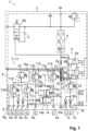
- Fig. 1 shows a pneumatic scheme of an air processing unit 1 comprising a multi-circuit protection valve assembly 2 and an air supply unit 3, the air supply unit 3 having a compressor port 3a, an air dryer cartridge 4 and operating valves 5 for setting different operating phases of the air supply unit 3.
- a compressor (not shown) can be connected to the compressor port 3a for providing compressed air that is dried in the air dryer cartridge 4 before it is supplied to the multi-circuit protection valve assembly 2 via an air inlet 2a.
- the dried compressed air is distributed to different consumer circuits C via main outlets 6; 6a-6g and extension outlets 7; 7a, 7b.
- the consumer circuits C may be (service, parking) brake circuits of the commercial vehicle, an air suspension system with suspension bellows and lift bellows, a pneumatically actuated gearing mechanism, a trailer supply circuit, and other possible pneumatic consumers.
- the air dryer cartridge 4 can preferably be regenerated in a regeneration mode by taking air from the multi-circuit protection valve assembly 2, e.g., via a regeneration valve 5a as one of the operating valves 5 of the air supply unit 3, and that is purged via a purging valve 5b as another operating valve 5.
- a compressor valve 5c is provided as another operating valve 5, wherein the compressor valve 5c is for switching off the compressor.
- the first main outlet 6a is protected by a first main overflow valve 11a located in a first main supply line 13a and the second main outlet 6b is protected by a second main overflow valve 11b located in a second main supply line 13b.
- a double check valve arrangement 15, comprising a first check valve 15a and a second check valve 15b is arranged between the first main supply line 13a and the second main supply line 13b behind the first and second main overflow valves 11a, 11b.
- the double check valve arrangement 15 allows to provide air from both main supply lines 13a, 13b to a pressure limiting valve 16 via an auxiliary line 16a while ensuring that both main supply lines 13a, 13b stay separated from each other.
- the pressure limiting valve 16 provides air to a third main overflow valve 11c located in a third main supply line 13c and to a fourth main overflow valve 11d located in a fourth main supply line 13d.
- a third check valve 17a and a fourth check valve 17b might be located before the fifth and the sixth main outlets 6e, 6f, respectively.
- an extension part 20 is included in the multi-circuit protection valve assembly 2.
- the extension part 20 comprises an extension inlet 21 that is connected to the supply channel 10 via an auxiliary outlet 19.
- the extension overflow valve 12 is located in an extension line 22 emanating from the extension inlet 21.
- the extension overflow valve 12 is connected to each of the extension outlets 7; 7a, 7b via additional fifth and sixth check valves 18a, 18b, respectively.
- air provided in the supply channel 10 is also supplied to the respective extension outlet 7; 7a, 7b protected by the extension overflow valve 12, thus, providing a fifth protected circuit with two additional extension ports.
- a control line 24 is connected to the supply channel 10, wherein the control line 24 leads to the regeneration valve 5a and the compressor valve 5c.
- the control pressure in the control line 24 can be used to carry out the respective function, e.g., providing air under control pressure for regenerating the air dryer cartridge 4 or switching the compressor.
- the multi-circuit protection valve assembly 2 comprises a main housing 2b that is one-parted or multi-parted, e.g., with several die casted parts screwed or bonded together.
- the main housing 2b can be made of, e.g., resin, another plastic material or metal.
- the main housing 2b comprises or encloses the elements of the multi-circuit protection valve assembly 2, in particular, the air inlet 2a, the main outlets 6, the auxiliary outlet 19, the supply channel 10, the main over-flow valves 11, the bypass valve arrangement 14, the double check valve arrangement 15, the pressure limiting valve 16, the check valves 17a, 17b, the lines 13, 16a, etc..
- elements of the air supply unit 3, in particular, the compressor port 3a, the operating valves 5, the air dryer cartridge 4, etc. are attached to or incorporated in this main housing 2b.
- the extension part 20 of the multi-circuit protection valve assembly 2 is a separate part that comprises an extension housing 25, e.g., a one-parted die casting part, made of, e.g., resin, another plastic material or metal.
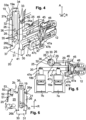
- the extension housing 25 is detachably fixed to the main housing 2b via the auxiliary outlet 19, as can be seen from Fig. 3 and 4 . Therefore, the extension housing 25 comprises a hollow cylindrical coupling part 26 with the extension inlet 21 being formed by a first opening 27a at a first terminal end 26a of the coupling part 26.
- a second terminal end 26b of the coupling part 26 comprises a second opening 27b which is for receiving a hollow screw 30 or banjo bolt.
- the hollow screw 30 comprises a closed head 31 on one end, a shaft 32 and an end region 33 opposite to the head 31, wherein the end region 33 has an external thread 33a on its outer surface.
- the end region 33 comprises an axial opening 34 (opening in an axial direction A with respect to the hollow screw 30) that transitions into a cavity 36 that axially extends through the end region 33 and the shaft 32 of the hollow screw 30 and that is axially delimited by an intermediate part 37 joint to or integral with the head 31.
- several radial openings 35 (openings in a radial direction R in relation to the hollow screw 30) are formed in the wall of the shaft 32 that are fluidly connected to the cavity 36.
- the hollow screw 30 can be axially inserted into the second opening 27b of the coupling part 26 until the head 31 touches the second terminal end 26b of the coupling part 26. In this position, at least the shaft 32 is coaxially located in a cylindrical inner chamber 28 of the coupling part 26 that connects the first opening 27a and the second opening 27b. In addition, the threaded end region 33 of the hollow screw 30 protrudes out of the second opening 27b. This allows the hollow screw 30 to be screwed into the auxiliary outlet 19 of the main housing 2b after positioning the extension inlet 21 coaxial to the auxiliary outlet 19. Therefore, the auxiliary outlet 19 comprises an internal thread 19a matching the external thread 33a of the end region 33 of the hollow screw 30.
- the coupling part 26 is clamped between the auxiliary outlet 19 of the main housing 2b and the head 31 of the hollow screw 30, as can be seen from Figs. 4 and 6 . Consequently, the extension part 20 can be attached to the main housing 2b via the hollow screw 30 in the first place.
- the construction of the hollow screw 30 allows the compressed air coming from the supply channel 10 to successively flow through the axial opening 34 of the hollow screw 30, the cavity 36, the radial openings 35 and into a feeding chamber 29.
- the feeding chamber 29 is formed in the extension housing 25, for example, running vertically away from the cylindrical inner chamber 28 of the coupling part 26 and the cavity 36 of the hollow screw 30 coaxially located therein.
- the cylindrical inner chamber 28 and the feeding chamber 29 are flow-connected via a feeding opening 29a.
- at least one of the radial openings 35 in the shaft 32 of the hollow screw 30 is at least partly overlapping with the feeding opening 29a of the feeding chamber 29, once the hollow screw 30 is in its screwed-in state.
- the feeding chamber 29 is enclosed or delimited by a spring-preloaded piston 45 that is a part of the extension overflow valve 12 being integrated into the extension housing 25 as well.
- the piston 45 is pressed against a valve seat 46 that is located around a circumference 47a of a terminal end 47b of an outlet channel 47 that is also integrally formed in the extension housing 25.
- the feeding chamber 29 is coaxially surrounding the cylindrical shaped outlet channel 47, both being separated by an outlet wall 47c.
- the piston 45 In the state of the extension overflow valve 12, shown in Fig. 4 and 5 , compressed air inside the feeding chamber 29 cannot flow into the outlet channel 47, as it is blocked by the piston 45 touching the valve seat 46. However, once the air pressure inside the feeding chamber 29 (and the supply channel 10) is high enough to overcome the spring force of the spring 48 preloading the piston 45, the piston 45 is lifted from the valve seat 46 allowing compressed air to flow from the feeding chamber 29 into the outlet channel 47, as indicated by a dashed-dotted line in Fig 4 .
- the cavity 36 inside the hollow screw 30 in the cylindrical inner chamber 28, the feeding chamber 29 and the outlet channel 47 are an exemplary implementation of the extension line 22 in which the extension overflow valve 12 is located and that is described above based on the pneumatic scheme of Fig. 1 .
- the outlet channel 47 comprises two valve openings 47d, 47e.
- the fifth check valve 18a is placed in the first valve opening 47d and the sixth check valve 18b is placed in the second valve opening 47e, e.g., via screwing or similar methods having the same effect.
- the check valves 18a, 18b are individually terminating into the respective extension outlets 7; 7a, 7b intended for connecting to the respective consumer circuits C.
- the extension part 20 can easily be attached to the main housing 2b via the hollow screw 30 to extend the functionality of the multi-circuit protection valve assembly 2 by providing two additional extension outlets 7; 7a, 7b that are protected against spreading leakages.
- the piston 45 On pressure loss in the outlet channel 47, e.g., due to such a leakage in a certain consumer circuit C connected to one of the extension outlets 7; 7a, 7b, the piston 45 is automatically pressed against the valve seat 46 by the spring force of the spring 48 preventing a pressure loss in the feeding chamber 29 as well as in the supply channel 10 connected thereto.
- a first sealing member 40 e.g., a sealing ring
- a second sealing member 41 e.g., a sealing ring
- Both sealing members 40, 41 ensure a gas-tight sealing of the extension part 20.
- the extension part 20 is additionally secured to the main housing 2b by a pin 50 as a securing means.
- the pin 50 is accommodated in a securing recess 51 formed in the extension housing 25 of the extension part 20, e.g., in a hollow cylindrical securing part 52 that is integral with the extension housing 25.
- the pin 50 might be screwed and/or bonded and/or snapped into the securing recess 51.
- the pin 50 projects out of the securing recess 51 such that it passes through a securing opening 53 in the main housing 2b, e.g., in a plate-like structure integral with the main housing 2b. This ensures that the extension part 20 cannot be twisted and/or tilted against the main housing 2b.
Landscapes
- Engineering & Computer Science (AREA)
- Mechanical Engineering (AREA)
- Transportation (AREA)
- General Engineering & Computer Science (AREA)
- Valves And Accessory Devices For Braking Systems (AREA)
Priority Applications (3)
| Application Number | Priority Date | Filing Date | Title |
|---|---|---|---|
| EP23206058.2A EP4545369B1 (fr) | 2023-10-26 | 2023-10-26 | Ensemble valves de protection à circuits multiples et unité de traitement d'air |
| CN202411469288.7A CN119900931A (zh) | 2023-10-26 | 2024-10-21 | 多回路保护阀组件及空气处理单元 |
| US18/924,225 US12583430B2 (en) | 2023-10-26 | 2024-10-23 | Multi-circuit protection valve assembly and air processing unit |
Applications Claiming Priority (1)
| Application Number | Priority Date | Filing Date | Title |
|---|---|---|---|
| EP23206058.2A EP4545369B1 (fr) | 2023-10-26 | 2023-10-26 | Ensemble valves de protection à circuits multiples et unité de traitement d'air |
Publications (2)
| Publication Number | Publication Date |
|---|---|
| EP4545369A1 true EP4545369A1 (fr) | 2025-04-30 |
| EP4545369B1 EP4545369B1 (fr) | 2026-01-28 |
Family
ID=88558337
Family Applications (1)
| Application Number | Title | Priority Date | Filing Date |
|---|---|---|---|
| EP23206058.2A Active EP4545369B1 (fr) | 2023-10-26 | 2023-10-26 | Ensemble valves de protection à circuits multiples et unité de traitement d'air |
Country Status (3)
| Country | Link |
|---|---|
| US (1) | US12583430B2 (fr) |
| EP (1) | EP4545369B1 (fr) |
| CN (1) | CN119900931A (fr) |
Families Citing this family (1)
| Publication number | Priority date | Publication date | Assignee | Title |
|---|---|---|---|---|
| EP4265494B1 (fr) * | 2022-04-21 | 2025-07-02 | ZF CV Systems Global GmbH | Unité de traitement d'air, système de gestion d'air, système pneumatique et véhicule |
Citations (2)
| Publication number | Priority date | Publication date | Assignee | Title |
|---|---|---|---|---|
| DE19842840A1 (de) * | 1998-09-18 | 2000-03-23 | Zahnradfabrik Friedrichshafen | Dämpfungsventil |
| EP3878704A1 (fr) * | 2020-03-09 | 2021-09-15 | ZF CV Systems Europe BV | Ensemble soupapes de protection multi-circuits pour un système de fluide sous pression |
Family Cites Families (31)
| Publication number | Priority date | Publication date | Assignee | Title |
|---|---|---|---|---|
| DE2437027A1 (de) * | 1974-08-01 | 1976-02-19 | Wabco Westinghouse Gmbh | Zweileitungs-zweikreisbremsanlage, drosselschaltung |
| US4441764A (en) * | 1981-01-14 | 1984-04-10 | General Signal | Relay valve assembly |
| DE3230970A1 (de) * | 1982-08-20 | 1984-02-23 | Bosch Gmbh Robert | Mehrkreis-bremsanlage |
| DE3434884C2 (de) * | 1984-09-22 | 2000-03-16 | Wabco Gmbh | Schutzsystem für eine Kraftfahrzeug-Druckluftanlage |
| US4685745A (en) * | 1985-01-23 | 1987-08-11 | Wabco Westinghouse Fahrzeugbremsen Gmbh | Motor vehicle brake pressure-regulating apparatus |
| DE3615002A1 (de) * | 1986-05-02 | 1987-11-05 | Wabco Westinghouse Fahrzeug | Einrichtung zum steuern des bremsdruckes |
| DE19514603C2 (de) * | 1995-04-20 | 1997-04-03 | Daimler Benz Ag | Druckluft-Bremsanlage für ein Nutzfahrzeug |
| GB9610068D0 (en) * | 1996-05-14 | 1996-07-17 | Grau Ltd | Brake system for a trailer vehicle and a valve for use therein |
| US20030146661A1 (en) * | 2002-02-01 | 2003-08-07 | Volvo Trucks North America, Inc. | Pressure protection manifold |
| WO2005014357A1 (fr) * | 2003-07-28 | 2005-02-17 | Wabco Gmbh & Co. Ohg | Systeme electronique a air comprime |
| JP4507556B2 (ja) * | 2003-10-27 | 2010-07-21 | ナブテスコオートモーティブ株式会社 | 4サーキットプロテクションバルブ |
| JP4743834B2 (ja) * | 2004-12-13 | 2011-08-10 | ナブテスコオートモーティブ株式会社 | プロテクションバルブ |
| DE102006034762B3 (de) * | 2006-07-27 | 2007-10-04 | Knorr-Bremse Systeme für Nutzfahrzeuge GmbH | Druckluftaufbereitungseinrichtung zum Versorgen einer Kraftfahrzeugbremsanlage mit Druckluft |
| DE102008047631A1 (de) * | 2008-09-17 | 2010-03-25 | Knorr-Bremse Systeme für Nutzfahrzeuge GmbH | Verfahren zum Betreiben eines Feststellbremsmoduls im Defektfall und zum Ausführen des Verfahrens geeignetes Feststellbremsmodul |
| DE102008048562A1 (de) * | 2008-09-23 | 2010-04-29 | Knorr-Bremse Systeme für Schienenfahrzeuge GmbH | Ventilanordnung zur Brems- sowie Zusatzgeräteansteuerung einer pneumatischen Bremsanlage eines Fahrzeuges |
| DE102011109500A1 (de) * | 2010-12-16 | 2012-06-21 | Wabco Gmbh | Druckluftversorgungsanlage, pneumatisches System und Verfahren zum Betreiben einer Pneumatikanlage |
| WO2012108501A1 (fr) * | 2011-02-10 | 2012-08-16 | ナブテスコオートモーティブ株式会社 | Soupape de protection |
| DE102011011395B3 (de) * | 2011-02-17 | 2012-05-31 | Knorr-Bremse Systeme für Nutzfahrzeuge GmbH | Mehrkreisschutzventil für eine Druckluftversorgungseinrichtung eines Fahrzeugs und Verfahren zum Betreiben eines Mehrkreisschutzventils |
| DE102011011634B4 (de) * | 2011-02-17 | 2012-12-06 | Knorr-Bremse Systeme für Nutzfahrzeuge GmbH | Druckluftversorgungseinrichtung für Nutzfahrzeuge |
| EP3168097B1 (fr) * | 2014-07-11 | 2019-10-30 | Nabtesco Automotive Corporation | Système de frein de stationnement |
| CN204956459U (zh) * | 2015-07-22 | 2016-01-13 | 十堰市华迪汽车零部件有限公司 | 车用四回路保护阀及与其集成的干燥器总成 |
| DE102017000694A1 (de) * | 2017-01-17 | 2018-07-19 | Wabco Gmbh | Mehrkreisschutzventil einer Druckluftbremsanlage |
| DE102017009307A1 (de) * | 2017-10-07 | 2019-04-11 | Wabco Gmbh | Parkbrems-Ventileinrichtung |
| GB2575696B (en) * | 2018-07-20 | 2022-07-13 | Haldex Brake Prod Ab | Vehicle braking system |
| DE102019103901A1 (de) * | 2019-02-15 | 2020-08-20 | Wabco Gmbh | Feststellbremsanordnung mit radindividueller ABS-Steuerung |
| US11021142B2 (en) * | 2019-07-08 | 2021-06-01 | Bendix Commercial Vehicle Systems Llc | Trailer control valve with integrated trailer supply |
| DE102019125747A1 (de) * | 2019-09-25 | 2021-03-25 | Wabco Europe Bvba | Elektropneumatische Parkbremsventileinheit |
| EP4265923A1 (fr) * | 2020-12-18 | 2023-10-25 | Semyungtech Co., Ltd. | Système de traitement d'air comprimé pour véhicule utilitaire |
| EP4265922A1 (fr) * | 2020-12-18 | 2023-10-25 | Semyungtech Co., Ltd. | Dispositif de traitement d'air comprimé pour véhicule utilitaire |
| EP4029746A1 (fr) * | 2021-01-19 | 2022-07-20 | KNORR-BREMSE Systeme für Nutzfahrzeuge GmbH | Soupape de protection commandée électroniquement |
| EP4112399B1 (fr) * | 2021-06-28 | 2024-01-03 | ZF CV Systems Europe BV | Séchoir à air chaud à chambre double et système pneumatique |
-
2023
- 2023-10-26 EP EP23206058.2A patent/EP4545369B1/fr active Active
-
2024
- 2024-10-21 CN CN202411469288.7A patent/CN119900931A/zh active Pending
- 2024-10-23 US US18/924,225 patent/US12583430B2/en active Active
Patent Citations (2)
| Publication number | Priority date | Publication date | Assignee | Title |
|---|---|---|---|---|
| DE19842840A1 (de) * | 1998-09-18 | 2000-03-23 | Zahnradfabrik Friedrichshafen | Dämpfungsventil |
| EP3878704A1 (fr) * | 2020-03-09 | 2021-09-15 | ZF CV Systems Europe BV | Ensemble soupapes de protection multi-circuits pour un système de fluide sous pression |
Also Published As
| Publication number | Publication date |
|---|---|
| US20250137542A1 (en) | 2025-05-01 |
| EP4545369B1 (fr) | 2026-01-28 |
| US12583430B2 (en) | 2026-03-24 |
| CN119900931A (zh) | 2025-04-29 |
Similar Documents
| Publication | Publication Date | Title |
|---|---|---|
| US10543449B2 (en) | Silencer, exhaust valve, valve device, air dryer, compressed air supply device for vehicle, and compressed air supply system | |
| US6585806B2 (en) | Air dryer reservoir module components | |
| US9017460B2 (en) | Silencer, exhaust valve, valve device, air dryer, compressed air supply device for vehicle, and compressed air supply system | |
| US5917139A (en) | Air dryer reservoir module | |
| JP5312038B2 (ja) | 圧縮空気処理装置及び圧縮空気処理装置の運転法 | |
| US12583430B2 (en) | Multi-circuit protection valve assembly and air processing unit | |
| US5678900A (en) | Unloader for a source of air under pressure on vehicles | |
| US9650029B2 (en) | Compressed air supply system and method for operating a compressed air supply system | |
| US12473936B2 (en) | Twin chamber air dryer and pneumatic system | |
| EP3556622B1 (fr) | Unité d'alimentation en air pour un système pneumatique d'un véhicule utilitaire | |
| US11617982B2 (en) | Arrangement for a utility vehicle | |
| JP2009023627A (ja) | 車両用圧縮空気供給システム | |
| US20100269926A1 (en) | Valve Device for a Compressed Air Supply Device and Compressed Air Supply System | |
| CN117366289A (zh) | 多回路保护阀和用于车辆的空气处理单元 | |
| EP3984843B1 (fr) | Soupape de protection commandée électroniquement | |
| KR20180112268A (ko) | 에어 제어밸브 및 이를 구비한 에어 처리 시스템 | |
| CN117360181A (zh) | 模块化的空气处理单元 | |
| KR102520425B1 (ko) | 상용차의 압축 공기 처리 장치용 언로딩 밸브 장치 | |
| US20250010832A1 (en) | Pneumatic valve system | |
| JP4974281B2 (ja) | マルチサーキットプロテクションバルブ | |
| USRE39467E1 (en) | Air dryer reservoir module components |
Legal Events
| Date | Code | Title | Description |
|---|---|---|---|
| PUAI | Public reference made under article 153(3) epc to a published international application that has entered the european phase |
Free format text: ORIGINAL CODE: 0009012 |
|
| STAA | Information on the status of an ep patent application or granted ep patent |
Free format text: STATUS: THE APPLICATION HAS BEEN PUBLISHED |
|
| AK | Designated contracting states |
Kind code of ref document: A1 Designated state(s): AL AT BE BG CH CY CZ DE DK EE ES FI FR GB GR HR HU IE IS IT LI LT LU LV MC ME MK MT NL NO PL PT RO RS SE SI SK SM TR |
|
| STAA | Information on the status of an ep patent application or granted ep patent |
Free format text: STATUS: REQUEST FOR EXAMINATION WAS MADE |
|
| 17P | Request for examination filed |
Effective date: 20250724 |
|
| GRAP | Despatch of communication of intention to grant a patent |
Free format text: ORIGINAL CODE: EPIDOSNIGR1 |
|
| STAA | Information on the status of an ep patent application or granted ep patent |
Free format text: STATUS: GRANT OF PATENT IS INTENDED |
|
| GRAS | Grant fee paid |
Free format text: ORIGINAL CODE: EPIDOSNIGR3 |
|
| INTG | Intention to grant announced |
Effective date: 20251113 |
|
| GRAA | (expected) grant |
Free format text: ORIGINAL CODE: 0009210 |
|
| STAA | Information on the status of an ep patent application or granted ep patent |
Free format text: STATUS: THE PATENT HAS BEEN GRANTED |
|
| AK | Designated contracting states |
Kind code of ref document: B1 Designated state(s): AL AT BE BG CH CY CZ DE DK EE ES FI FR GB GR HR HU IE IS IT LI LT LU LV MC ME MK MT NL NO PL PT RO RS SE SI SK SM TR |
|
| REG | Reference to a national code |
Ref country code: CH Ref legal event code: F10 Free format text: ST27 STATUS EVENT CODE: U-0-0-F10-F00 (AS PROVIDED BY THE NATIONAL OFFICE) Effective date: 20260128 Ref country code: GB Ref legal event code: FG4D |
|
| REG | Reference to a national code |
Ref country code: DE Ref legal event code: R096 Ref document number: 602023011237 Country of ref document: DE |
|
| REG | Reference to a national code |
Ref country code: IE Ref legal event code: FG4D |