EP4545783A2 - Fonctionnement a puissance reduite d'une eolienne - Google Patents
Fonctionnement a puissance reduite d'une eolienne Download PDFInfo
- Publication number
- EP4545783A2 EP4545783A2 EP25158193.0A EP25158193A EP4545783A2 EP 4545783 A2 EP4545783 A2 EP 4545783A2 EP 25158193 A EP25158193 A EP 25158193A EP 4545783 A2 EP4545783 A2 EP 4545783A2
- Authority
- EP
- European Patent Office
- Prior art keywords
- speed
- wind
- power
- reduced
- wind speed
- Prior art date
- Legal status (The legal status is an assumption and is not a legal conclusion. Google has not performed a legal analysis and makes no representation as to the accuracy of the status listed.)
- Pending
Links
Images

Classifications
-
- F—MECHANICAL ENGINEERING; LIGHTING; HEATING; WEAPONS; BLASTING
- F03—MACHINES OR ENGINES FOR LIQUIDS; WIND, SPRING, OR WEIGHT MOTORS; PRODUCING MECHANICAL POWER OR A REACTIVE PROPULSIVE THRUST, NOT OTHERWISE PROVIDED FOR
- F03D—WIND MOTORS
- F03D7/00—Controlling wind motors
- F03D7/02—Controlling wind motors the wind motors having rotation axis substantially parallel to the air flow entering the rotor
- F03D7/0276—Controlling wind motors the wind motors having rotation axis substantially parallel to the air flow entering the rotor controlling rotor speed, e.g. variable speed
-
- F—MECHANICAL ENGINEERING; LIGHTING; HEATING; WEAPONS; BLASTING
- F03—MACHINES OR ENGINES FOR LIQUIDS; WIND, SPRING, OR WEIGHT MOTORS; PRODUCING MECHANICAL POWER OR A REACTIVE PROPULSIVE THRUST, NOT OTHERWISE PROVIDED FOR
- F03D—WIND MOTORS
- F03D7/00—Controlling wind motors
- F03D7/02—Controlling wind motors the wind motors having rotation axis substantially parallel to the air flow entering the rotor
- F03D7/028—Controlling wind motors the wind motors having rotation axis substantially parallel to the air flow entering the rotor controlling wind motor output power
- F03D7/0284—Controlling wind motors the wind motors having rotation axis substantially parallel to the air flow entering the rotor controlling wind motor output power in relation to the state of the electric grid
-
- F—MECHANICAL ENGINEERING; LIGHTING; HEATING; WEAPONS; BLASTING
- F03—MACHINES OR ENGINES FOR LIQUIDS; WIND, SPRING, OR WEIGHT MOTORS; PRODUCING MECHANICAL POWER OR A REACTIVE PROPULSIVE THRUST, NOT OTHERWISE PROVIDED FOR
- F03D—WIND MOTORS
- F03D7/00—Controlling wind motors
- F03D7/02—Controlling wind motors the wind motors having rotation axis substantially parallel to the air flow entering the rotor
- F03D7/04—Automatic control; Regulation
- F03D7/042—Automatic control; Regulation by means of an electrical or electronic controller
- F03D7/048—Automatic control; Regulation by means of an electrical or electronic controller controlling wind farms
-
- F—MECHANICAL ENGINEERING; LIGHTING; HEATING; WEAPONS; BLASTING
- F03—MACHINES OR ENGINES FOR LIQUIDS; WIND, SPRING, OR WEIGHT MOTORS; PRODUCING MECHANICAL POWER OR A REACTIVE PROPULSIVE THRUST, NOT OTHERWISE PROVIDED FOR
- F03D—WIND MOTORS
- F03D9/00—Adaptations of wind motors for special use; Combinations of wind motors with apparatus driven thereby; Wind motors specially adapted for installation in particular locations
- F03D9/20—Wind motors characterised by the driven apparatus
- F03D9/25—Wind motors characterised by the driven apparatus the apparatus being an electrical generator
-
- H—ELECTRICITY
- H02—GENERATION; CONVERSION OR DISTRIBUTION OF ELECTRIC POWER
- H02J—ELECTRIC POWER NETWORKS; CIRCUIT ARRANGEMENTS OR SYSTEMS FOR SUPPLYING OR DISTRIBUTING ELECTRIC POWER; SYSTEMS FOR STORING ELECTRIC ENERGY
- H02J3/00—Circuit arrangements for AC mains or AC distribution networks
- H02J3/38—Arrangements for feeding a single network from two or more generators or sources in parallel; Arrangements for feeding already energised networks from additional generators or sources in parallel
- H02J3/381—Dispersed generators
-
- H—ELECTRICITY
- H02—GENERATION; CONVERSION OR DISTRIBUTION OF ELECTRIC POWER
- H02J—ELECTRIC POWER NETWORKS; CIRCUIT ARRANGEMENTS OR SYSTEMS FOR SUPPLYING OR DISTRIBUTING ELECTRIC POWER; SYSTEMS FOR STORING ELECTRIC ENERGY
- H02J3/00—Circuit arrangements for AC mains or AC distribution networks
- H02J3/38—Arrangements for feeding a single network from two or more generators or sources in parallel; Arrangements for feeding already energised networks from additional generators or sources in parallel
- H02J3/46—Controlling the sharing of generated power between the generators, sources or networks
-
- F—MECHANICAL ENGINEERING; LIGHTING; HEATING; WEAPONS; BLASTING
- F05—INDEXING SCHEMES RELATING TO ENGINES OR PUMPS IN VARIOUS SUBCLASSES OF CLASSES F01-F04
- F05B—INDEXING SCHEME RELATING TO WIND, SPRING, WEIGHT, INERTIA OR LIKE MOTORS, TO MACHINES OR ENGINES FOR LIQUIDS COVERED BY SUBCLASSES F03B, F03D AND F03G
- F05B2220/00—Application
- F05B2220/70—Application in combination with
- F05B2220/706—Application in combination with an electrical generator
-
- F—MECHANICAL ENGINEERING; LIGHTING; HEATING; WEAPONS; BLASTING
- F05—INDEXING SCHEMES RELATING TO ENGINES OR PUMPS IN VARIOUS SUBCLASSES OF CLASSES F01-F04
- F05B—INDEXING SCHEME RELATING TO WIND, SPRING, WEIGHT, INERTIA OR LIKE MOTORS, TO MACHINES OR ENGINES FOR LIQUIDS COVERED BY SUBCLASSES F03B, F03D AND F03G
- F05B2270/00—Control
- F05B2270/10—Purpose of the control system
- F05B2270/103—Purpose of the control system to affect the output of the engine
- F05B2270/1033—Power (if explicitly mentioned)
-
- F—MECHANICAL ENGINEERING; LIGHTING; HEATING; WEAPONS; BLASTING
- F05—INDEXING SCHEMES RELATING TO ENGINES OR PUMPS IN VARIOUS SUBCLASSES OF CLASSES F01-F04
- F05B—INDEXING SCHEME RELATING TO WIND, SPRING, WEIGHT, INERTIA OR LIKE MOTORS, TO MACHINES OR ENGINES FOR LIQUIDS COVERED BY SUBCLASSES F03B, F03D AND F03G
- F05B2270/00—Control
- F05B2270/10—Purpose of the control system
- F05B2270/107—Purpose of the control system to cope with emergencies
- F05B2270/1077—Storm protection
-
- F—MECHANICAL ENGINEERING; LIGHTING; HEATING; WEAPONS; BLASTING
- F05—INDEXING SCHEMES RELATING TO ENGINES OR PUMPS IN VARIOUS SUBCLASSES OF CLASSES F01-F04
- F05B—INDEXING SCHEME RELATING TO WIND, SPRING, WEIGHT, INERTIA OR LIKE MOTORS, TO MACHINES OR ENGINES FOR LIQUIDS COVERED BY SUBCLASSES F03B, F03D AND F03G
- F05B2270/00—Control
- F05B2270/30—Control parameters, e.g. input parameters
- F05B2270/32—Wind speeds
- F05B2270/3201—"cut-off" or "shut-down" wind speed
-
- H—ELECTRICITY
- H02—GENERATION; CONVERSION OR DISTRIBUTION OF ELECTRIC POWER
- H02J—ELECTRIC POWER NETWORKS; CIRCUIT ARRANGEMENTS OR SYSTEMS FOR SUPPLYING OR DISTRIBUTING ELECTRIC POWER; SYSTEMS FOR STORING ELECTRIC ENERGY
- H02J2101/00—Supply or distribution of decentralised, dispersed or local electric power generation
- H02J2101/20—Dispersed power generation using renewable energy sources
- H02J2101/28—Wind energy
-
- Y—GENERAL TAGGING OF NEW TECHNOLOGICAL DEVELOPMENTS; GENERAL TAGGING OF CROSS-SECTIONAL TECHNOLOGIES SPANNING OVER SEVERAL SECTIONS OF THE IPC; TECHNICAL SUBJECTS COVERED BY FORMER USPC CROSS-REFERENCE ART COLLECTIONS [XRACs] AND DIGESTS
- Y02—TECHNOLOGIES OR APPLICATIONS FOR MITIGATION OR ADAPTATION AGAINST CLIMATE CHANGE
- Y02E—REDUCTION OF GREENHOUSE GAS [GHG] EMISSIONS, RELATED TO ENERGY GENERATION, TRANSMISSION OR DISTRIBUTION
- Y02E10/00—Energy generation through renewable energy sources
- Y02E10/70—Wind energy
- Y02E10/72—Wind turbines with rotation axis in wind direction
-
- Y—GENERAL TAGGING OF NEW TECHNOLOGICAL DEVELOPMENTS; GENERAL TAGGING OF CROSS-SECTIONAL TECHNOLOGIES SPANNING OVER SEVERAL SECTIONS OF THE IPC; TECHNICAL SUBJECTS COVERED BY FORMER USPC CROSS-REFERENCE ART COLLECTIONS [XRACs] AND DIGESTS
- Y02—TECHNOLOGIES OR APPLICATIONS FOR MITIGATION OR ADAPTATION AGAINST CLIMATE CHANGE
- Y02E—REDUCTION OF GREENHOUSE GAS [GHG] EMISSIONS, RELATED TO ENERGY GENERATION, TRANSMISSION OR DISTRIBUTION
- Y02E10/00—Energy generation through renewable energy sources
- Y02E10/70—Wind energy
- Y02E10/76—Power conversion electric or electronic aspects
Definitions
- the present invention relates to a method for operating a wind turbine.
- the present invention also relates to a wind turbine.
- Wind turbines are well known for generating electrical power from wind and typically feeding this power into an electrical grid, which is regularly maintained by grid operators. Ideally, wind turbines are operated in what is known as grid-parallel operation, in which each wind turbine generates and feeds as much power into the electrical grid as is possible based on the prevailing wind, taking into account the technical limitations of the respective wind turbine.
- Reduced-power operating modes were developed to meet the requirements of grid operators, who, for example, request only throttled feed-in power from wind turbines or wind farms during high wind conditions to prevent overloading of the electrical grid.
- a reduced rated power level can be specified, with a corresponding reduced rated speed interpolated from a power-optimized operating mode. This reduced power value is thus specified that lies below the normal rated power of the wind turbine.
- a speed is assigned to this reduced rated power, which can be considered a reduced rated speed.
- This corresponding rated speed, which is assigned to this reduced power, i.e., the reduced rated power level, can be taken from a speed-power characteristic curve intended for partial load operation of the wind turbine.
- Such a speed-power characteristic curve thus represents the relationship between speed and power in partial load operation. As the speed increases, higher power is assigned, and this specific assignment indicates the speed-power characteristic curve.
- reduced-power operation in which the power is reduced to a value that is lower than the turbine could actually generate at that moment, less power is extracted from the wind than would be possible. This can be achieved by turning the rotor blades out of the wind so that the aerodynamic rotor extracts less power from the wind than would be possible at that moment. From the generator's point of view, this corresponds to a situation in which there is actually correspondingly less wind. Accordingly, it is obvious to set the same speed-power value for artificial power reduction as in the case of a prevailing wind, which leads to the same power value.
- the rated power is achieved at a so-called rated wind speed. If this rated power is reduced in the reduced operating mode, a reduced rated wind speed can also be assumed for the reduced-power operating mode, because the reduced rated power is already achieved at lower wind speeds.
- the wind turbine regulates to the corresponding rated speed by adjusting the rotor blades, which is also generally referred to as pitching the rotor blades. is referred to, regardless of the wind speed, at least as long as there is no storm operation.
- the control system does not take wind speed into account, but merely regulates the turbine to nominal power and nominal speed. If, for example, the wind speed increases in this operating mode, the speed and power may briefly increase slightly, although this is counteracted by the control system, particularly by pitching the rotor blades. As long as the generator torque remains constant—for example, because the excitation of a separately excited synchronous generator remains unchanged—controlling to a constant nominal speed essentially inevitably leads to constant power, usually the nominal power.
- the wind turbine regulates to a wind speed-dependent speed, which can drop from the nominal speed to a spin speed during storm operation.
- the wind turbine operates at different speeds at the same wind speed.
- Another particularly noticeable effect is that the speed and thus the rotational speed are lower in reduced-power operation than in optimal-power operation.
- the tip speed ratio ⁇ which indicates the ratio of the rotational speed of the aerodynamic rotor at its blade tips to the wind speed, decreases with increasing wind speed and is lower in reduced-power operation than in optimal-power operation.
- German Patent and Trademark Office has searched the following prior art in the priority application for this application: DE 198 44 258 A1 , DE 10 2015 203 841 A1 , DE 10 2016 124 630 A1 and US 2012/0139246 A1 .
- the invention is therefore based on the object of addressing at least one of the above-mentioned problems.
- a solution is proposed that minimizes torsional vibrations during reduced-power operation.
- an alternative solution to previously known solutions is proposed.
- a method for operating a wind turbine is proposed according to claim 1. Accordingly, a wind turbine is assumed which has an aerodynamic rotor with rotor blades, in particular three rotor blades are proposed. This aerodynamic rotor or the wind turbine as a whole can be operated at a variable rotor speed. During operation, the wind turbine outputs power generated from wind for feeding into an electrical supply grid. Furthermore, it is provided that the wind turbine can be operated in a normal operating mode without power reduction and in a reduced operating mode with power reduction. In particular, a specification for a power reduction can be required externally, in particular by a grid operator who operates the electrical supply grid.
- the wind turbine when operating in the reduced operating mode for wind speeds above a nominal wind speed, increases its rotor speed at least in a speed increase range as the wind speed continues to increase, while the power remains reduced.
- the reduced operating mode is specifically considered here, and the normal operating mode is assumed to operate preferably in a known manner.
- the power reduction results in a reduced A power value is specified, which can also be referred to as the reduced target power.
- This reduced target power is below the normal rated power of the wind turbine, i.e., below the unreduced rated power, which can also be referred to as the nominal system power.
- the wind turbine then initially operates in partial load mode by increasing its power and speed in tandem with the increasing wind speed. This increase in power and speed continues until the power reaches the specified limit, i.e., until the turbine power reaches the specified reduced target power. Previously, the power and speed were then maintained at this value, which can therefore also be referred to as the reduced rated speed or reduced target power.
- reducing generator excitation i.e., reducing generator torque
- the power i.e., the wind turbine's output power
- the rated wind speed can also be a reduced rated wind speed, namely the speed at which the output power, based on the usual speed-power characteristic curve, reaches the value of the reduced specified power.
- the reduced rated wind speed therefore refers to the reduced operating mode.
- a rated wind speed is often related to the operating mode used and refers to the wind speed at which the maximum power in the relevant operating range is achieved. It is also possible that the rotor speed will only be increased when the wind continues to increase above the normal rated wind speed, i.e. the wind speed at which the output power, based on the normal speed-power characteristic curve, reaches the normal rated power of the wind turbine.
- the load on the wind turbine can surprisingly be reduced by further increasing the speed despite the power limitation.
- This can result in a higher tip speed ratio compared to an operating curve in which the speed would not be increased any further.
- This can prevent stalls on the pressure side of the rotor blade profile and, in particular, only locally occurring stalls can be avoided, which in turn can prevent torsional loads and thus torsional vibrations of the rotor blade.
- This then leads to an overall lower load compared to an operating mode in which such local stalls and corresponding torsional loads and torsional vibrations would occur.
- the stalls on the pressure side can also result in significantly increased noise emissions from the wind turbine.
- the increase in speed and the associated avoidance of stalls also prevents increased noise emissions due to separation noise from the turbine.
- the surprising effect arises that an increase in speed leads to a reduction in noise, or at least counteracts a further increase in noise.
- the speed in the reduced-power operating mode is increased as the wind speed increases, up to a maximum of the normal, i.e., unreduced, rated speed.
- a further increase in speed due to the described effect of avoiding local stall, can initially result in an overall reduced load, which is more significant than a small increase in load due to a higher speed.
- a speed increase cannot be carried out arbitrarily and that the normal, unreduced rated speed is a good value that should not be exceeded if possible.
- a normal rated speed is often significantly higher than a reduced rated speed. It is preferably proposed that the rotor speed be increased in the reduced operating mode to values above the normal rated speed.
- the rotor speed is not only increased to values of the rated speed, but can also be increased to values above this, at least in one section. Accordingly, despite the reduced power, the speed is still increased above the rated speed. It has been recognized that a load reduction can be achieved even by increasing the speed above the rated speed.
- the wind turbine be operated in partial load mode, full load mode, or storm mode depending on the prevailing wind speed.
- the wind turbine therefore has These three operating modes are assigned to a wind speed range. The specific selection of the respective operating mode can be made depending on the measured wind speed, but it can also be made depending on state variables.
- the wind speed is below the nominal wind speed, meaning that the maximum power generation cannot be achieved.
- the output power then depends on the wind speed, and in particular, the wind turbine is operated in such a way that the output power is as high as possible.
- the wind speed is at or above the nominal wind speed, but below a storm wind speed, so that the maximum power that can be generated is achieved.
- the maximum power that can be generated can be referred to as the nominal power.
- the nominal system power is the normal nominal power for which the wind turbine is designed.
- the reduced specified power can also be regarded as a reduced nominal power, because it also refers to a power that must not be exceeded, but which is below the nominal system power and can be specified. It is therefore not determined by the design of the wind turbine, but can be specified during operation, particularly by a grid operator.
- the wind speed is at or above the initial storm wind speed, and to protect the wind turbine, less than the maximum power is generated, i.e. at least less than the normal rated power, i.e. at least less than the nominal turbine power.
- This serves to protect the wind turbine, and here the initial storm wind speed can be specified as a fixed value and refers to a wind speed above which storm operation can be assumed for the wind turbine in question and the wind turbine is operated accordingly.
- the storm wind speed is a general term that describes wind speeds during storm operation, i.e. the initial storm wind speed and the wind speeds above this. A wind speed below the initial storm wind speed is therefore also below the initial storm wind speed.
- the following is proposed for the rotor speed of the wind turbine in reduced operating mode and at full load.
- the wind turbine For wind speeds above the nominal wind speed up to an increase wind speed that is above the nominal wind speed and below the initial storm wind speed, the wind turbine maintains its rotor speed constant at a reduced nominal speed.
- the wind turbine For wind speeds above the increase wind speed, the wind turbine increases its rotor speed. The increase occurs in such a way that it increases continuously, particularly linearly, with further increasing wind speed up to the initial storm wind speed, or that it increases continuously with further increasing wind speed up to a normal nominal speed.
- a boost wind speed is therefore specified, and this essentially lies within the full-load operating range. It is therefore higher than the nominal wind speed and lower than the initial storm wind speed. Accordingly, it is specifically proposed that the rotor speed in reduced operating mode should not be increased any further from the nominal wind speed until the wind speed has reached the boost wind speed. The rotor speed should then be increased as the wind speed continues to rise. It was particularly recognized here that initially, i.e. at comparatively low wind speeds in full-load operation, a speed increase in reduced operating mode is not necessary because problems due to low tip speed ratios are not initially expected. Only later, when the wind speed has increased further, can the described stall phenomena occur at low tip speed ratios. Such a boost wind speed is defined accordingly. In particular, it can be slightly below a wind speed at which the aforementioned problems could otherwise arise due to a low tip speed ratio.
- the method of increasing the rotor speed from the initial wind speed can vary, and two variants are proposed here.
- the rotor speed is increased particularly from the initial wind speed as the wind speed continues to rise until the initial storm wind speed. This is when a storm occurs, and the wind turbine's operation must be reduced again so that the turbine loads are not exceeded.
- such a wind speed-dependent rotor speed curve can then also achieve the rotor speed curve in normal operating mode.
- the rotor speed is increased from the increased wind speed up to a normal rated speed.
- the rotor speed is increased in the reduced operating mode from the increased wind speed until it reaches the wind speed characteristic curve or the wind speed-dependent speed curve of the normal operating mode. From this moment or this state onward, the further operation of at least the rotor speed can be controlled in the same way as in the normal operating mode as the wind speed continues to increase in the reduced operating mode.
- the output power and/or the rotor speed in partial load operation be adjusted depending on a predetermined characteristic curve, in particular a speed-power characteristic curve, until the output power has reached the value of the reduced specified power.
- the same operating management can basically be used as in a normal operating mode.
- the output power is adjusted depending on the speed-power characteristic curve. This is done in particular in such a way that, depending on a detected rotor speed, the output power is adjusted according to the speed-power characteristic curve.
- the rotor blade angle is constant, namely constant in particular throughout the entire partial load operation. If the rotor speed then remains constant at the set output power, a stable operating point has been established.
- the output power is further changed accordingly; in the example mentioned, it is increased, but could also be reduced. This also increases or decreases the generator torque or the counter torque, so that This will result in a stable operating point being found by continuously adjusting the output power according to the speed-power characteristic curve.
- the output power is set, and the rotor speed is determined.
- the rotor speed is also indirectly adjusted as a function of the speed-power characteristic.
- both the output power and the rotor speed are adjusted as a function of the speed-power characteristic.
- a generator torque can also be adjusted in a similar way instead of the output power.
- the output power is regulated to the value of the reduced specified power and, at the same time, the rotor speed is adjusted as a function of a detected, in particular measured, wind speed, in particular based on a wind speed-speed characteristic curve.
- the control concept be fundamentally changed. It is changed from controlling power and speed as a function of the speed-power characteristic curve to two essentially independent control branches. The output power is therefore simply regulated to a constant value, regardless of the wind speed.
- the output power and rotor speed be adjusted depending on the detected, particularly measured, wind speed.
- this adjustment is based on a characteristic curve for each of these two variables.
- a different control concept is proposed for storm operation, according to which both the speed and the power are adjusted depending on a detected wind speed.
- such an adjustment can, of course, be implemented using a closed-loop control system.
- the increase in rotor speed in the reduced operating mode above the nominal speed is carried out as a function of a variable representative of a load on the rotor blades, in particular as a function of a detected vibration of at least one of the rotor blades, in particular a torsional vibration.
- This makes it possible to counteract such a vibration directly.
- it is considered rather unusual to increase the speed when vibrations of the rotor blades occur, because in principle an increase in speed tends to lead to an increase in load.
- an increase in speed leads to an increase in the tip speed ratio and can prevent torsional vibrations in this operating mode.
- the increase in rotor speed be quantitatively controlled as a function of the load or a representative value.
- Load-dependent speed control is particularly suitable here.
- the rotor speed be increased in the reduced operating mode above the nominal speed as soon as the variable representative of a load on the rotor blades or the detected vibration of at least one of the rotor blades exceeds a predetermined load limit.
- loads can be recorded here and a limit value can be defined, exceeding which leads to a reaction, namely an increase in the rotor speed.
- the two alternatives mentioned can also be combined, namely in that the mentioned load both triggers an increase in the rotor speed and this load also quantitatively leads to the increase in the rotor speed.
- the normal operating mode is based on a normal speed characteristic curve that depends on the wind speed.
- the normal speed characteristic essentially describes the speed value as a function of the wind speed. This does not necessarily mean that the speed is controlled entirely based on this normal speed characteristic, meaning it is always set depending on the detected wind speed.
- This normal speed characteristic initially forms the basis for a design, i.e., it is used for the design of the wind turbine. It can also be used in sections, particularly during storm operation, but can also actually be used to adjust the speed.
- the reduced operating mode is based on a reduced speed characteristic curve that depends on the wind speed. This also describes the speed curve as a function of the wind speed, but here for the reduced operating mode. However, this does not necessarily mean that the rotor speed is adjusted in every range depending on this speed characteristic curve, i.e., depending on the wind speed, although this can be the case, at least in part.
- the reduced speed characteristic it is proposed that in full load operation up to a converging wind speed, it has lower speed values than the normal speed characteristic at the same wind speed values, and that from the converging wind speed onwards, for further increasing wind speeds, the reduced speed characteristic partially or completely agrees with the normal speed characteristic.
- the reduced speed characteristic has, at least in sections, higher speeds than the normal speed characteristic.
- the reduced speed characteristic intersects the normal speed characteristic at the converging wind speed and then initially has higher values as the wind speed continues to increase. At the latest at wind speed values at which the output power reaches the reduced specified power in normal operating mode in storm operation, the two speed characteristics can agree.
- the reduced speed characteristic refers to the speed characteristic assigned to the reduced operating mode. It does not necessarily have to have a lower speed than the normal speed characteristic.
- the rotor speed at nominal wind speed is lower than at the initial storm wind speed and/or that the merging wind speed corresponds to or is lower than the initial storm wind speed. It is therefore particularly proposed that the rotor speed in the reduced operating mode increases towards the initial storm wind speed even in full load operation. It should also be noted that a speed increase usually only occurs in partial load operation up to full load operation and that the speed is not increased further in full load operation in order to avoid loads. Here it is proposed to increase the rotor speed further in full load operation and thus achieve a load reduction. Here the increase itself is proposed in the direction of storm operation, although a speed reduction is expected to reduce loads precisely in storm operation.
- a speed curve dependent on the wind speed is specified, which is the same in normal operating mode and the reduced operating mode until the output power reaches the reduced specified power.
- the rotor speed value that is established when the output power has reached the reduced specified power forms a reduced nominal speed, with a reduced nominal wind speed simultaneously prevailing.
- the reduced nominal speed is below a nominal turbine speed, and the reduced nominal wind speed is below a nominal turbine wind speed.
- the rotor blades are adjusted such that the output power is not increased any further.
- the output power maintains the value of the reduced specified power and the rotor speed is kept at the value of the reduced nominal speed.
- the boost wind speed be at least 10% above the nominal wind speed, in particular 10% above the nominal wind speed of the normal operating mode, i.e., 10% above the nominal wind speed of the turbine. Furthermore, it is proposed that the boost wind speed be at least 10% below the initial storm wind speed. Thus, a significant range is provided within which the rotor speed can be increased from the boost wind speed to the initial storm wind speed. At the same time, however, it is proposed that an increase not occur immediately from the nominal speed, but only at a significantly higher wind speed.
- the rotor speed and the output power in partial load operation are controlled depending on a speed-power characteristic curve, wherein the same speed-power characteristic curve is used for the normal operating mode and the reduced operating mode up to the reduced specified power or down to the reduced nominal power.
- the rotor speed and the output power are reduced as the wind speed increases, starting from a wind speed above the second storm wind speed, which is greater than the initial storm wind speed.
- a speed characteristic curve dependent on the wind speed is specified for the reduction of the rotor speed, and a power characteristic curve is specified for the reduction of the output power.
- the same speed characteristic curve and the same power characteristic curve for wind speeds above the second storm wind speed are used for the normal operating mode and the reduced operating mode.
- different power curves be used for the normal operating mode and the reduced operating mode for the range from the initial storm wind speed to the second storm wind speed.
- the speed curves are identical in this range, at least in some sections.
- a wind turbine which has corresponding devices for carrying out at least one method for operating a wind turbine according to an embodiment described above.
- the electric generator can preferably be designed as a separately excited or constant excitation synchronous generator.
- a gearless wind turbine is preferably proposed, in which the aerodynamic rotor is directly mechanically connected to an electrodynamic rotor or rotor of the generator.
- the feed-in device is preferably designed as an inverter or inverter arrangement with multiple inverters. These can receive their power from the generator, either via a rectifier that supplies a direct current or a direct voltage, which the inverter then converts into feed-in alternating current.
- the feed-in device it is also possible for the feed-in device to be designed as a full converter, in particular as a so-called back-to-back converter, which generates an alternating current on one side and receives an alternating current for a generator on another side. With this other side, it can also at least partially control the generator, namely in particular can control a multi-phase stator current of the generator.
- the switching device for switching the operation of the wind turbine between normal operating mode and reduced operating mode can preferably be provided in a process computer and implemented there, for example, as a control device, namely, for example, programmed.
- control device can also be embodied in the same process computer or in a further process computer, and the described control steps can thus be implemented by this process computer.
- control device is connected to the feed-in device in such a way that it sends control signals to the feed-in device.
- the control device can also be configured to send signals to the switching device. It is also possible for the control device to be connected to measuring devices, in particular to measuring devices for detecting the wind speed, a rotor speed, and/or an output power of the wind turbine.
- the switching device is part of the control device.
- the wind turbine is configured to implement at least one method for operating a wind turbine according to one of the above-described embodiments, by performing this entirely or partially by means of the control device.
- the control device is thus configured to implement at least one of the above-described methods for operating a wind turbine.
- a wind farm which has a plurality of wind turbines according to at least one embodiment of the wind turbines described above.
- the wind farm can have a central farm control system in order to provide a reduced specified power to each of the wind turbines, in particular depending on a total power reduction for the wind farm received externally.
- a grid operator can use this system to transmit a total power reduction to the wind farm as a specification, e.g., as a corresponding request signal. This can be done directly to the farm control system.
- the wind farm then converts this received total power reduction into individual power reductions for the individual wind turbines. This can be done using concrete values, or it can also be done as a percentage.
- the central farm control system preferably records the power actually fed into the electrical supply grid or the sum of all output powers of the wind turbines of the wind farm and can determine, depending on this, whether the total power reduction received externally is achieved or not. and then, if necessary, adjust the reduced power outputs to the wind turbines. This can also be done as absolute values or as a percentage, which, for example, specifies a percentage value for each wind turbine relative to its nominal power.
- Figure 1 shows a wind turbine 100 with a tower 102 and a nacelle 104.
- a rotor 106 with three rotor blades 108 and a spinner 110 is arranged on the nacelle 104.
- the rotor 106 is set into rotation by the wind and thereby drives a generator in the nacelle 104.
- a generator 130 is indicated in the nacelle 104, which generates electrical power and transmits it to an inverter 132, whereby the alternating current generated by the generator was previously rectified.
- the inverter 132 feeds Transformer 134 at a grid connection point 136 into the electrical supply network 138.
- a control device 140 is provided to control the inverter 132, which forms a feed-in device.
- a reduction signal R can be sent to a switching device 142.
- the switching device 142 which can also be part of the control device 140, then initiates a change from the normal operating mode to the reduced operating mode.
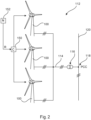
- FIG. 2 shows a wind farm 112 with, for example, three wind turbines 100, which may be identical or different.
- the three wind turbines 100 are thus representative of essentially any number of wind turbines in a wind farm 112.
- the wind turbines 100 provide their power, namely in particular the generated electricity, via an electrical farm grid 114.
- the currents or power generated by the individual wind turbines 100 are added together, and a transformer 116 is usually provided, which steps up the voltage in the farm and then feeds it into the supply grid 120 at the feed-in point 118, which is also generally referred to as a PCC.
- Fig. 2 is only a simplified representation of a wind farm 112, which, for example, does not show a control system, although a control system is of course present.
- the farm network 114 can also be designed differently, for example, by also having a transformer at the output of each wind turbine 100, to name just one other embodiment.
- the wind farm 112 of the Figure 2 may additionally comprise a central wind farm controller 150.
- This central wind farm controller 150 can receive a power reduction signal R from a grid operator 152 and thus from an external source.
- the central wind farm controller 150 can output individual values or percentage values for the power reduction of the individual wind turbines 100 from this reduction signal R.
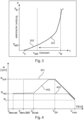
- Figure 3 schematically shows two operating curves, namely so-called speed-power characteristic curves.
- the first speed-power characteristic curve 301 relates to a normal operating mode, namely a so-called power-optimized operating characteristic curve.
- the system operation is optimized and the speed-power characteristic curve 301 is optimally designed and also matched to the rotor blade and the correspondingly selected blade angle.
- the power P thus increases from a starting speed n 0 with increasing speed up to the rated speed n N and then also reaches the rated power P N , namely the rated system power.
- a reduced-power operating characteristic curve 302 corresponds, at least initially, to the first operating characteristic curve, i.e., the first speed-power characteristic curve 301, until it reaches the reduced rated speed n NR and the reduced rated power P NR . Then, the reduced target power, which corresponds to this reduced rated power P NR , is reached, and the output power may not be increased any further. At the same time, the rotor speed n is essentially frozen at this low speed value. The rotor speed n then has this reduced rated power speed value n NR and maintains it.
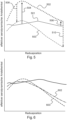
- Figure 4 shows, according to one embodiment of the invention, a profile of a rotor speed for three operating cases, namely a power-optimized profile 401, a power-reduced, improved profile 402 and a power-reduced, non-improved profile 403.
- Figure 4 shows the relationship between the rotational speed and the wind speed in the full-load range of the respective operating mode, i.e., for wind speeds above the nominal wind speed applicable to the respective operating mode. Partial-load operation until the nominal speed is reached is not shown for reasons of clarity.
- the power-optimized curve 401 thus shows the power-optimized operating mode OM0.
- the turbine is controlled to the constant nominal speed N setpoint up to the initial storm wind speed V SA , at which the turbine transitions to storm operation by linearly reducing the speed from the nominal speed N setpoint of the power-optimized mode OM0 to the spin speed Nt at the cut-off wind speed Vmax.
- the reduced power mode has, as mentioned, a lower nominal speed N red and an equally reduced nominal wind speed V Nenn,red , in Figure 4 represented by the power-reduced, non-improved curve 403.
- N red the nominal speed of the turbine
- V max the shutdown wind speed of the turbine
- the wind speed V SA,red does not have to be greater than V Nenn,OM0 as indicated in the figure, but can also be lower, but is always greater than V Nenn,red .
- the wind speed V SA,red can be determined in advance through simulations and depends at least on the turbine type and the reduced rated power. Alternatively, it is suggested that vibrations be measured during turbine operation and that the turbine be run to a higher speed if threshold values are exceeded.
- the wind speed V SA,red is in any case not a fixed value, but differs from turbine type to turbine type due to the different rotor blade designs.
- Figure 5 explains why the state of the art can lead to high negative angles of attack in the outer area of the blade and why the proposal according to the invention leads to higher angles of attack, i.e. fewer negative angles of attack.
- the tip speed ratios decrease continuously, and the blade angles, also known as pitch angles, increase continuously.
- the radius R is derived from the radius of the aerodynamic rotor and is used in the sense as the radius R of the rotor blade, which basically means the length of the rotor blade plus the remaining distance from the blade root to the axis of rotation.
- the radius positions of the rotor blade according to the diagrams of the Figures 5 and 6 refer to it. The maximum radius position thus corresponds to the blade tip and the minimum to the rotor blade root.
- the influence of decreasing tip speed ratio and increasing pitch angle on the angle of attack applied to the blade varies and should be calculated using the Figure 5
- the solid line 501 shows a typical angle of attack curve over the blade radius in the power-optimal operating mode, also referred to as "OM0", in the partial load range.
- the angle of attack increases are greatest in the inner area of the blade and decrease towards the blade tip, in Figure 5 indicated by the two solid arrows 504 and 506. If the pitch angle also increases with increasing wind speeds during nominal load operation, which can also be referred to as full-load operation, then the dashed angle of attack distribution 503 is established. An increase in the pitch angle leads to an approximately uniform decrease in the aerodynamic angle of attack, indicated by the dashed arrows 508 and 510.
- the rotor blade experiences very low tip speed ratios combined with large pitch angles.
- the result is a high gradient in the aerodynamic angles of attack across the blade radius, with higher angles of attack in the inner region of the blade and correspondingly lower angles of attack in the outer region, which can exhibit highly negative values.
- the angles of attack become so low that flow separation can occur on the pressure side of the rotor blade profile, a condition known as negative stall.
- Figure 6 explains the proposal according to the invention, or at least part of it.
- the proposal according to the invention starts with the operational management of the turbine in order to solve the problem of the high negative angle of attack in the outer region of the blade.
- high negative angles of attack in the outer region of the blade are the result of low tip speed ratios and simultaneously high blade pitch angles.
- the inventive proposal of increasing the speed at constant, reduced electrical power results in an increase in the tip speed ratios and a simultaneous decrease in the pitch angles when conditions with identical wind speeds are considered.
- the pitch angle decreases because, with unchanged wind speed and constant rated power, the power coefficient of the turbine remains constant. If one looks at the characteristic diagram of the rotor blade, one can see that at low tip speed ratios the pitch angle decreases when one moves along the isoline of the power coefficient in the direction of increasing tip speed ratios.
- a simultaneous increase in tip speed ratio and decrease in pitch angle with unchanged turbine power then leads to an angle of attack distribution in the proposed new operating mode as in Figure 6 represented by the dashed line 602.
- the angles of attack decrease in the inner blade area, but increase in the outer blade area, as desired.
- the angle of attack in the outer area of the blade reduces the risk of flow separation on the pressure side of the rotor blade with the negative effects already mentioned.
- the invention thus serves the purpose of preventing operating conditions during wind turbine operation in which aeroelastic phenomena lead to rotor blade vibrations, which can result in increased turbine loads. Furthermore, the invention serves the purpose of preventing significantly increased noise emissions during strong wind/storm operation of the turbine.
Landscapes
- Engineering & Computer Science (AREA)
- Life Sciences & Earth Sciences (AREA)
- Sustainable Development (AREA)
- Sustainable Energy (AREA)
- Chemical & Material Sciences (AREA)
- Combustion & Propulsion (AREA)
- Mechanical Engineering (AREA)
- General Engineering & Computer Science (AREA)
- Power Engineering (AREA)
- Wind Motors (AREA)
- Control Of Eletrric Generators (AREA)
Applications Claiming Priority (3)
| Application Number | Priority Date | Filing Date | Title |
|---|---|---|---|
| DE102018114935.2A DE102018114935A1 (de) | 2018-06-21 | 2018-06-21 | Leistungsreduzierter Betrieb einer Windenergieanlage |
| EP19730335.7A EP3810924B1 (fr) | 2018-06-21 | 2019-06-12 | Fonctionnement à puissance réduite d'une éolienne |
| PCT/EP2019/065320 WO2019243129A1 (fr) | 2018-06-21 | 2019-06-12 | Fonctionnement à puissance réduite d'une éolienne |
Related Parent Applications (1)
| Application Number | Title | Priority Date | Filing Date |
|---|---|---|---|
| EP19730335.7A Division EP3810924B1 (fr) | 2018-06-21 | 2019-06-12 | Fonctionnement à puissance réduite d'une éolienne |
Publications (2)
| Publication Number | Publication Date |
|---|---|
| EP4545783A2 true EP4545783A2 (fr) | 2025-04-30 |
| EP4545783A3 EP4545783A3 (fr) | 2025-07-09 |
Family
ID=66857903
Family Applications (2)
| Application Number | Title | Priority Date | Filing Date |
|---|---|---|---|
| EP25158193.0A Pending EP4545783A3 (fr) | 2018-06-21 | 2019-06-12 | Fonctionnement a puissance reduite d'une eolienne |
| EP19730335.7A Active EP3810924B1 (fr) | 2018-06-21 | 2019-06-12 | Fonctionnement à puissance réduite d'une éolienne |
Family Applications After (1)
| Application Number | Title | Priority Date | Filing Date |
|---|---|---|---|
| EP19730335.7A Active EP3810924B1 (fr) | 2018-06-21 | 2019-06-12 | Fonctionnement à puissance réduite d'une éolienne |
Country Status (7)
| Country | Link |
|---|---|
| US (1) | US11353005B2 (fr) |
| EP (2) | EP4545783A3 (fr) |
| CN (1) | CN112313408A (fr) |
| DE (1) | DE102018114935A1 (fr) |
| DK (1) | DK3810924T3 (fr) |
| ES (1) | ES3028536T3 (fr) |
| WO (1) | WO2019243129A1 (fr) |
Families Citing this family (4)
| Publication number | Priority date | Publication date | Assignee | Title |
|---|---|---|---|---|
| US11530685B2 (en) * | 2020-08-20 | 2022-12-20 | General Electric Company | System and method for managing output flicker generated by a wind farm |
| CN114607555B (zh) * | 2020-12-03 | 2024-10-18 | 金风科技股份有限公司 | 用于风力发电机组的控制方法及装置 |
| DK4102057T3 (da) * | 2021-06-11 | 2026-02-09 | Wobben Properties Gmbh | Fremgangsmåde til styring af rotorhastigheden af en vindmølle |
| JP2023043004A (ja) * | 2021-09-15 | 2023-03-28 | 株式会社東芝 | 機械構造物の応力推定方法および機械構造物の監視方法 |
Citations (4)
| Publication number | Priority date | Publication date | Assignee | Title |
|---|---|---|---|---|
| DE19844258A1 (de) | 1998-09-26 | 2000-03-30 | Dewind Technik Gmbh | Windenergieanlage |
| US20120139246A1 (en) | 2009-08-14 | 2012-06-07 | Suzlon Energy Gmbh | Asynchronous generator system and wind turbine having an asynchronous generator system |
| DE102015203841A1 (de) | 2015-03-04 | 2016-09-08 | Wobben Properties Gmbh | Verfahren zum Betreiben einer Windenergieanlage |
| DE102016124630A1 (de) | 2016-12-16 | 2018-06-21 | Wobben Properties Gmbh | Verfahren zum Steuern einer Windenergieanlage |
Family Cites Families (10)
| Publication number | Priority date | Publication date | Assignee | Title |
|---|---|---|---|---|
| DE102004054608B4 (de) * | 2004-09-21 | 2006-06-29 | Repower Systems Ag | Verfahren zur Regelung einer Windenergieanlage und Windenergieanlage mit einem Rotor |
| AU2009265828B2 (en) | 2008-06-30 | 2014-05-22 | Vestas Wind Systems A/S | Power curtailment of wind turbines |
| CN101813059A (zh) * | 2010-03-08 | 2010-08-25 | 江苏省电力试验研究院有限公司 | 低额定风速风力发电系统的功率控制方法 |
| CN102562453B (zh) * | 2012-03-01 | 2013-09-04 | 国电联合动力技术有限公司 | 变速恒频风力发电机在额定转速阶段的变桨控制方法 |
| CN104736845B (zh) * | 2012-08-14 | 2017-11-14 | 维斯塔斯风力系统有限公司 | 用于风力涡轮机控制的部分负载降额 |
| US9115695B2 (en) * | 2013-07-16 | 2015-08-25 | Siemens Aktiengesellschaft | Method and arrangement for controlling a wind turbine |
| KR101575071B1 (ko) * | 2013-12-02 | 2015-12-07 | 두산중공업 주식회사 | 풍력 발전 단지의 발전량 제어 방법 |
| DE102014206884A1 (de) * | 2014-04-09 | 2015-10-15 | Wobben Properties Gmbh | Verfahren zum Einspeisen elektrischer Energie mittels einer Windenergieanlage |
| US10495062B2 (en) * | 2015-03-05 | 2019-12-03 | Vestas Wind Systems A/S | Power ramping a turbine from a low-power mode |
| DK3489507T3 (da) * | 2017-11-28 | 2023-07-31 | Nordex Energy Se & Co Kg | Fremgangsmåde og anordning til drift af et vindenergianlæg |
-
2018
- 2018-06-21 DE DE102018114935.2A patent/DE102018114935A1/de active Pending
-
2019
- 2019-06-12 EP EP25158193.0A patent/EP4545783A3/fr active Pending
- 2019-06-12 EP EP19730335.7A patent/EP3810924B1/fr active Active
- 2019-06-12 US US17/254,690 patent/US11353005B2/en active Active
- 2019-06-12 WO PCT/EP2019/065320 patent/WO2019243129A1/fr not_active Ceased
- 2019-06-12 ES ES19730335T patent/ES3028536T3/es active Active
- 2019-06-12 DK DK19730335.7T patent/DK3810924T3/da active
- 2019-06-12 CN CN201980041661.XA patent/CN112313408A/zh active Pending
Patent Citations (4)
| Publication number | Priority date | Publication date | Assignee | Title |
|---|---|---|---|---|
| DE19844258A1 (de) | 1998-09-26 | 2000-03-30 | Dewind Technik Gmbh | Windenergieanlage |
| US20120139246A1 (en) | 2009-08-14 | 2012-06-07 | Suzlon Energy Gmbh | Asynchronous generator system and wind turbine having an asynchronous generator system |
| DE102015203841A1 (de) | 2015-03-04 | 2016-09-08 | Wobben Properties Gmbh | Verfahren zum Betreiben einer Windenergieanlage |
| DE102016124630A1 (de) | 2016-12-16 | 2018-06-21 | Wobben Properties Gmbh | Verfahren zum Steuern einer Windenergieanlage |
Also Published As
| Publication number | Publication date |
|---|---|
| US11353005B2 (en) | 2022-06-07 |
| DE102018114935A1 (de) | 2019-12-24 |
| WO2019243129A1 (fr) | 2019-12-26 |
| DK3810924T3 (da) | 2025-05-26 |
| EP3810924A1 (fr) | 2021-04-28 |
| ES3028536T3 (en) | 2025-06-19 |
| CN112313408A (zh) | 2021-02-02 |
| EP4545783A3 (fr) | 2025-07-09 |
| EP3810924B1 (fr) | 2025-02-26 |
| US20210115898A1 (en) | 2021-04-22 |
Similar Documents
| Publication | Publication Date | Title |
|---|---|---|
| EP2556247B1 (fr) | Régulation d'inertie dynamique | |
| EP2411669B2 (fr) | Procédé de fonctionnement d'une éolienne | |
| EP1125060B1 (fr) | Logique de commande pour centrale eolienne | |
| EP2063111B1 (fr) | Procédé de fonctionnement d'une éolienne | |
| EP2694808B1 (fr) | Éolienne et procédé pour faire fonctionner une éolienne | |
| EP1668245B1 (fr) | Eolienne dotee d'un module de puissance reactive pour le support du reseau et procede associe | |
| EP2457320B1 (fr) | Procédé de fonctionnement d'une turbine éolienne et turbine éolienne associée | |
| EP3810924B1 (fr) | Fonctionnement à puissance réduite d'une éolienne | |
| EP3735532B1 (fr) | Fonctionnement d'une éolienne en cas de tempête | |
| EP2288016B1 (fr) | Eolienne dotée d'une courbe caractéristique de la vitesse de rotation modifiable | |
| EP3533125B1 (fr) | Procédé de commande d'une installation électrique éolienne | |
| EP3749851B1 (fr) | Procédé pour commander un aérogénérateur et aérogénérateur correspondant | |
| EP1892412A1 (fr) | Procédé de fonctionnement d'éoliennes | |
| EP2284974A1 (fr) | Procédé de fonctionnement ou de réglage d'une éolienne et procédé de préparation de la puissance de régulation à l'aide d'une éolienne | |
| EP3926162B1 (fr) | Procédé de fonctionnement d'une éolienne, dispositif de commande destiné au fonctionnement d'un éolienne et parc éolien | |
| EP3443223B1 (fr) | Procédé pour faire fonctionner une éolienne | |
| EP3444938A1 (fr) | Procédé de commande d'une éolienne | |
| EP3735740B1 (fr) | Installation d'énergie éolienne pour injecter d'énergie électrique au moyen d'un convertisseur | |
| EP3754178B1 (fr) | Procédé de fonctionnement d'un parc éolien | |
| EP3842633B1 (fr) | Procédé de fonctionnement d'une éolienne, éolienne et parc éolien | |
| EP4148270B1 (fr) | Procédé d'ajustement d'une courbe caractéristique de fonctionnement d'une éolienne | |
| EP3848575A1 (fr) | Procédé de fonctionnement d'un parc éolien comprenant plusieurs éoliennes ainsi que parc éolien correspondant | |
| WO2020044323A1 (fr) | Éolienne pourvue d'un dispositif d'amortissement pour le mode vrille | |
| EP3931437B1 (fr) | Procédé servant à faire fonctionner une éolienne en cas de défaillance de réseau | |
| EP3916219B1 (fr) | Procédé de commande d'une éolienne |
Legal Events
| Date | Code | Title | Description |
|---|---|---|---|
| PUAI | Public reference made under article 153(3) epc to a published international application that has entered the european phase |
Free format text: ORIGINAL CODE: 0009012 |
|
| STAA | Information on the status of an ep patent application or granted ep patent |
Free format text: STATUS: THE APPLICATION HAS BEEN PUBLISHED |
|
| AC | Divisional application: reference to earlier application |
Ref document number: 3810924 Country of ref document: EP Kind code of ref document: P |
|
| AK | Designated contracting states |
Kind code of ref document: A2 Designated state(s): AL AT BE BG CH CY CZ DE DK EE ES FI FR GB GR HR HU IE IS IT LI LT LU LV MC MK MT NL NO PL PT RO RS SE SI SK SM TR |
|
| PUAL | Search report despatched |
Free format text: ORIGINAL CODE: 0009013 |
|
| AK | Designated contracting states |
Kind code of ref document: A3 Designated state(s): AL AT BE BG CH CY CZ DE DK EE ES FI FR GB GR HR HU IE IS IT LI LT LU LV MC MK MT NL NO PL PT RO RS SE SI SK SM TR |
|
| RIC1 | Information provided on ipc code assigned before grant |
Ipc: F03D 7/02 20060101AFI20250604BHEP |