EP4545854A1 - Régulation d'un dispositif de combustion - Google Patents
Régulation d'un dispositif de combustion Download PDFInfo
- Publication number
- EP4545854A1 EP4545854A1 EP23205942.8A EP23205942A EP4545854A1 EP 4545854 A1 EP4545854 A1 EP 4545854A1 EP 23205942 A EP23205942 A EP 23205942A EP 4545854 A1 EP4545854 A1 EP 4545854A1
- Authority
- EP
- European Patent Office
- Prior art keywords
- sensor
- combustion
- designed
- test
- control
- Prior art date
- Legal status (The legal status is an assumption and is not a legal conclusion. Google has not performed a legal analysis and makes no representation as to the accuracy of the status listed.)
- Granted
Links
Images


Classifications
-
- F—MECHANICAL ENGINEERING; LIGHTING; HEATING; WEAPONS; BLASTING
- F23—COMBUSTION APPARATUS; COMBUSTION PROCESSES
- F23N—REGULATING OR CONTROLLING COMBUSTION
- F23N5/00—Systems for controlling combustion
- F23N5/02—Systems for controlling combustion using devices responsive to thermal changes or to thermal expansion of a medium
- F23N5/12—Systems for controlling combustion using devices responsive to thermal changes or to thermal expansion of a medium using ionisation-sensitive elements, i.e. flame rods
- F23N5/123—Systems for controlling combustion using devices responsive to thermal changes or to thermal expansion of a medium using ionisation-sensitive elements, i.e. flame rods using electronic means
-
- F—MECHANICAL ENGINEERING; LIGHTING; HEATING; WEAPONS; BLASTING
- F23—COMBUSTION APPARATUS; COMBUSTION PROCESSES
- F23N—REGULATING OR CONTROLLING COMBUSTION
- F23N5/00—Systems for controlling combustion
- F23N5/02—Systems for controlling combustion using devices responsive to thermal changes or to thermal expansion of a medium
- F23N5/10—Systems for controlling combustion using devices responsive to thermal changes or to thermal expansion of a medium using thermocouples
- F23N5/102—Systems for controlling combustion using devices responsive to thermal changes or to thermal expansion of a medium using thermocouples using electronic means
-
- F—MECHANICAL ENGINEERING; LIGHTING; HEATING; WEAPONS; BLASTING
- F23—COMBUSTION APPARATUS; COMBUSTION PROCESSES
- F23N—REGULATING OR CONTROLLING COMBUSTION
- F23N2227/00—Ignition or checking
- F23N2227/20—Calibrating devices
-
- F—MECHANICAL ENGINEERING; LIGHTING; HEATING; WEAPONS; BLASTING
- F23—COMBUSTION APPARATUS; COMBUSTION PROCESSES
- F23N—REGULATING OR CONTROLLING COMBUSTION
- F23N2229/00—Flame sensors
- F23N2229/14—Flame sensors using two or more different types of flame sensor
-
- F—MECHANICAL ENGINEERING; LIGHTING; HEATING; WEAPONS; BLASTING
- F23—COMBUSTION APPARATUS; COMBUSTION PROCESSES
- F23N—REGULATING OR CONTROLLING COMBUSTION
- F23N2900/00—Special features of, or arrangements for controlling combustion
- F23N2900/05001—Measuring CO content in flue gas
Definitions
- the present disclosure relates to control curves as used in connection with combustion sensors in combustion devices, for example, in gas burners.
- Combustion sensors in combustion devices are, for example, ionization electrodes.
- the present disclosure relates to the correction of such control curves, taking into account the aging and/or drift of a sensor signal.
- the air ratio ⁇ can be determined during combustion using a combustion sensor.
- the air ratio ⁇ characterizes a quantitative ratio of air to fuel, in particular fuel gas.
- the air ratio ⁇ is determined as the quotient of the actual air quantity present in a mixture flow and the air quantity required for stoichiometric combustion of the mixture flow.
- the air ratio ⁇ can be determined using an ionization current through an ionization electrode. An alternating voltage is first applied to the combustion sensor, in particular to the ionization electrode. Due to the rectifying effect of a flame, an ionization current flows as a direct current.
- the ionization current detected by the combustion sensor is plotted against the speed of the combustion device's fan.
- the ionization current is typically measured in microamperes.
- the speed of the combustion device's fan is typically measured in revolutions per minute.
- the speed of the combustion device's fan is both a measure of the air supply and the combustion device's burner output, i.e., the amount of heat per unit of time.
- the recorded ionization current can be plotted in control curves directly against the air supply or the burner output.
- a multitude of setpoints are plotted along such a control curve. Initially, such setpoints can be recorded on a sample device under laboratory conditions as part of testing and/or adjustments. The recorded values are stored and incorporated into a control and/or regulation system, particularly an electronic control and/or regulation system.
- Combustion sensors are subject to aging during operation.
- This aging is caused by deposits and/or coatings during the operation of a combustion device.
- an oxide layer can form on the surface of an ionization electrode, the thickness of which changes over the course of operating hours.
- a signal drift occurs.
- the ionization current of ionization electrodes drifts due to aging. Therefore, a control curve recorded under laboratory conditions requires periodic review and/or correction, at the latest after one to three thousand hours of operation.
- a control device with correction of the control curve of an ionization electrode is disclosed in the European patent EP2466204B1
- the European patent EP2466204B1 was granted on 13 November 2013 to SIEMENS AG.
- a corresponding registration EP2466204A1 was published on 16 December 2010 submitted and published on June 20, 2012.
- the control curve is corrected using a three-step test procedure.
- the test procedure is referred to below as the calibration and/or drift test.
- the control device performs controlled operation at a defined air supply, speed, or power.
- the control device controls or regulates the actuators of the combustion device to a changed supply ratio. In particular, the speed of the fan of a combustion device is changed. By controlling the actuators, the control device adjusts the air supply to the combustion device.
- the modified feed ratio is above the stoichiometric value of the air ratio ⁇ of 1.
- the air ratio ⁇ is reduced by 0.1 or 0.06 to values greater than or equal to 1.05.
- a new target value is calculated from the ionization current recorded during this process and from stored data.
- EP3045816B1 Device for controlling a combustion device, was granted on 12 December 2018 .
- a corresponding registration EP3045816A1 was published on 20 July 2016 published.
- EP3045816B1 discloses and claims a control system that calculates a shifted ionization current for a different fan speed based on a current ionization current and a previously recorded ionization current. The shifted ionization current can then be filtered to the historical ionization current of the other speed.
- EP4119847B1 Combustion device with control device, granted on 14 June 2023 .
- a corresponding registration EP4119847A1 was published on 18 January 2023 published.
- EP4119847B1 claims a combustion device with a list of reference points. Each reference point is assigned a drift test value and an index for determining a test result. Based on this index, a decision is made about determining a test result for a given air supply. As a function of the test result Finally, a modified drift test value is determined and assigned to the relevant support point as a drift test value.
- correcting the control curve requires that the heat generated during the calibration and/or drift test can also be dissipated to consumers such as heating or domestic water. Otherwise, the amount of heat generated during the calibration and/or drift test will be higher than the amount of heat consumed. As a result, the temperature in the system rises, and the system's temperature controller shuts down the combustion device if the temperature exceeds a specified threshold difference. In this case, the calibration and/or drift test at a specific air supply cannot be completed.
- a time delay is caused by the adjustment of at least one variable selected from the air supply or the fan speed to a changed fan speed setpoint.
- the subject of the present disclosure is an improved control of a combustion device which at least partially overcomes the aforementioned disadvantages.
- the present disclosure relates to a supervision test on a combustion device with a combustion sensor.
- the combustion sensor can, for example, be or include an ionization electrode.
- the combustion sensor can also be or include a temperature sensor.
- Combustion sensors, in particular ionization electrodes are subject to aging during operation. This aging necessitates calibration. Calibration determines the extent to which target values and/or test results of a combustion sensor, in particular an ionization electrode, have shifted as a result of aging.
- an air supply area has not been calibrated within a specified time period, this area is marked for a supervision test. If the combustion device operates with an air supply and/or fan speed within the marked area, a supervision test is requested. The supervision test is performed immediately or shortly after the combustion device begins operating in the marked area.
- the temperature setpoint can also be increased.
- the combustion device regulates to the changed setpoint.
- a device for controlling and/or regulating the combustion device regulates to the changed, in particular increased, setpoint.
- a control signal can be output to an actuator of the combustion device, such as a gas valve.
- the control of the combustion device remains stable for a specified period of time.
- the specified period can, for example, be at least five seconds, at least ten seconds, or even at least one minute. Longer periods allow for more reliable statements regarding the stability of the control of the combustion device.
- control of the combustion device can remain stable for a specified period of time with a closed control loop.
- the specified period can, for example, be at least five seconds, at least ten seconds, or even at least one minute. Longer periods allow for more reliable statements about the stability of the combustion device's control.
- the stability of the control system can be detected, among other things, by ensuring that, after a change such as an increase in the setpoint, the setpoint is at least reached within a defined time period. Furthermore, the stability of the control system can be detected by ensuring that, after a change in the setpoint, a predefined band around the changed, particularly increased, setpoint is reached.
- the predefined band around the changed, particularly increased, setpoint can, for example, be a predefined tolerance band around the changed, particularly increased, setpoint.
- An instability in the control of the combustion device can be detected, for example, if an actual value of the control loop falls below or exceeds a threshold.
- An instability in the control of the combustion device can also be detected if an actual value of the control loop falls below or exceeds a threshold within a certain period of time.
- Instability in the combustion device's control system can also be detected by an actual value changing too quickly over time. Instability in the combustion device's control system can also be detected by the actual value changing too quickly within a given time period. In particular, the actual value may decrease too quickly.
- the specified time period can be, for example, one second.
- a change that is too rapid could, for example, be halving or quartering the actual value.
- a change that is too rapid could, in particular, be halving or quartering the actual value within the specified time period.
- control loop can break. This means that the control loop is no longer closed.
- the supervision test is passed.
- the combustion device returns to normal operation after a passed supervision test.
- the combustion device can return to normal control operation after a passed supervision test by resetting the setpoint to its original value.
- normal control operation comprises control of the combustion air ratio ⁇ and power control.
- the device for controlling and/or regulating the combustion device can return to normal operation, such as normal control operation, after the supervision test.
- a check for a pass or fail result of the supervision test can be carried out based on a carbon monoxide concentration in the exhaust gas.
- An exhaust gas sensor can be used to record a signal indicating a carbon monoxide concentration in the exhaust gas.
- the combustion device can comprise an exhaust gas sensor for carbon monoxide in an exhaust duct or in a chimney of the combustion device.
- the exhaust gas sensor for carbon monoxide is connected via signal technology to the device for controlling and/or regulating the combustion device.
- the control and/or regulating device therefore receives a signal from the exhaust gas sensor for carbon monoxide and processes the signal into a measured value of the carbon monoxide concentration.
- a faulty result of the supervision test can be detected, for example, if the measured value of the carbon monoxide concentration exceeds a threshold value.
- a faulty result of the supervision test can also be detected if the measured value of the carbon monoxide concentration exceeds a predetermined threshold value.
- the device for controlling and/or regulating the combustion device detects such a Exceeding a threshold value.
- the measured value of the carbon monoxide concentration is a measured value of the carbon monoxide concentration in a flue gas duct or in a chimney of the combustion device.
- combustion control here can be carried out not only by an ionization electrode or a temperature sensor in the combustion chamber, but also by an oxygen sensor in the exhaust gas.
- the combustion device can comprise an exhaust gas sensor for oxygen in an exhaust duct or in a chimney of the combustion device.
- the exhaust gas sensor for oxygen is connected via signal technology to the device for controlling and/or regulating the combustion device.
- the control and/or regulating device thus receives a signal from the exhaust gas sensor for oxygen and processes the signal into a measured value of the oxygen concentration.
- the air actuator comprises at least one actuator selected from an air damper or a fan.
- the air actuator comprises an air damper and a fan.
- the air actuator comprises exactly one actuator selected from an air damper or a fan.
- the fuel actuator comprises at least one actuator selected from a valve or a fuel flap.
- the fuel actuator comprises a valve and a fuel flap.
- the fuel actuator comprises exactly one actuator selected from a valve or a fuel flap.
- An incorrect result of the supervision test can also be identified if the measured carbon monoxide concentration changes too quickly over time.
- An incorrect result of the supervision test can also be identified if the measured carbon monoxide concentration changes too quickly within a given period of time. In particular, the measured carbon monoxide concentration may increase too quickly within the given period of time.
- the predetermined time period can be, for example, one second.
- the device for controlling and/or regulating the combustion device detects such an excessively rapid change in the measured value of the carbon monoxide concentration in the exhaust duct of the combustion device. In one embodiment, the device for controlling and/or regulating the combustion device detects such an excessively rapid change in the measured value of the carbon monoxide concentration in the chimney of the combustion device.
- a change that is too rapid is, for example, a doubling or a fivefold increase in the measured carbon monoxide concentration.
- a change that is too rapid can, in particular, be a doubling or a fivefold increase in the measured carbon monoxide concentration within the specified time period. Low values for the change in the measured carbon monoxide concentration allow for timely detection of an erroneous result in the supervision test.
- a faulty supervision test result may be indicated if the carbon monoxide sensor signal exceeds a threshold, such as a predefined threshold. This means that at least one carbon monoxide signal is greater than the predefined threshold. Furthermore, at least one measured value obtained from the carbon monoxide signal may be greater than the predefined threshold. Furthermore, a faulty supervision test result may be indicated if the carbon monoxide sensor signal changes too quickly over time.
- a threshold such as a predefined threshold.
- normal operation includes Control of the combustion air ratio ⁇ and power control.
- the device for controlling and/or regulating the combustion device can return to normal operation, such as normal control operation, after the supervision test.
- the third quantity w 3 can be calculated in this way.
- the coefficients a , b, c and d are preferably rational numbers.
- the third quantity w 3 is compared with a threshold value ⁇ , in particular compared mathematically. If, for example, at least one of the conditions w 3 > ⁇ or w 3 ⁇ ⁇ or w 3 ⁇ ⁇ or w 3 ⁇ ⁇ is met, it is concluded that the result of the supervision test is incorrect.
- FIG 1 shows a combustion device.
- the combustion device comprises a burner 1, such as a wall-mounted gas burner and/or an oil burner.
- a flame of a heat generator burns in the combustion chamber 2 of the combustion device.
- the heat generator exchanges the thermal energy of the hot combustion gases into another fluid, such as water.
- the warm water is used, for example, to operate a hot water heating system and/or to heat drinking water.
- the thermal energy of the hot fuels and/or combustion gases can be used to heat a product, for example in an industrial process.
- the heat generator is part of a combined heat and power plant.
- the heat generator can be used to heat water in a plant for the extraction of lithium and/or lithium carbonate.
- the exhaust gases 9 are discharged from the combustion chamber 2, for example, via a chimney 8.
- the air supply 4 for the combustion process is supplied via a (motor-driven) fan 3.
- a control and/or regulating device 10 specifies the air supply V L to be delivered to the drive of the fan 3.
- the fan speed becomes a measure of the air supply 4.
- the fan speed is reported back to the control and/or regulating device 10 by the fan 3.
- the control and/or regulating device 10 determines the speed of the fan 3 via the signal line 12.
- the control and/or regulating device 10 preferably comprises a microcontroller.
- the control and/or regulating device 10 ideally comprises a microprocessor.
- the control and/or regulating device 10 can be a control device.
- the control device preferably comprises a microcontroller.
- the control device ideally comprises a microprocessor.
- the control device can comprise a proportional and integral controller.
- the control device can comprise a proportional and integral and derivative controller.
- control and/or regulating device 10 may comprise a field-programmable (logic) gate arrangement. Furthermore, the control and/or regulating device 10 may comprise an application-specific integrated circuit.
- signal line 11 comprises an optical fiber.
- the signal line 12 for determining the fan speed can also comprise an optical fiber.
- signal lines 11 and 12 are designed as optical fibers. Optical fibers provide advantages with regard to galvanic isolation and protection against explosions.
- the damper and/or valve position can be used as a measure for the air supply 4.
- a measured value derived from the signal of a pressure sensor and/or mass flow sensor and/or volume flow sensor can be used.
- This sensor is advantageously arranged in the duct for the air supply 4. This sensor advantageously provides a signal that is converted into a flow measurement value using a suitable signal processing unit.
- the signal from that sensor is fed back via a signal line.
- a signal that is a measure of an air supply 4 can be fed back to the control and/or regulating device 10 via the signal line.
- the signal line can comprise an optical fiber.
- Optical fibers provide advantages with regard to galvanic isolation and protection against explosions.
- a suitable signal processing device for processing the sensor signal ideally comprises at least one analog-to-digital converter.
- the signal processing device, in particular the analog-to-digital converter(s) is integrated into the control and/or regulating device 10.
- the measured value of a pressure sensor and/or a mass flow sensor in a side channel of the air supply 4 can also be used as a measure for the air supply V L.
- a combustion device with a supply channel and a side channel is described, for example, in the European patent EP3301364B1 The European patent EP3301364B1 was published on 7 June 2017 and granted on August 7, 2019.
- a combustion device with a feed channel and side channel is claimed, with a mass flow sensor extending into the feed channel.
- a pressure sensor and/or a mass flow sensor in the side channel detects a signal corresponding to the pressure value dependent on the air supply V L and/or the air flow (particle and/or mass flow) in the side channel.
- the sensor advantageously provides a signal that is converted into a measured value using a suitable signal processing device.
- the signals from multiple sensors are converted into a common measured value.
- a suitable signal processing device ideally comprises at least one analog-to-digital converter.
- the signal processing device, in particular the analog-to-digital converter(s) is integrated into the control and/or regulating device 10.
- the signal processing device, in particular the analog-to-digital converter(s) is integrated into the pressure sensor and/or mass flow sensor.
- the sensor signals are transmitted to the control and/or regulating device 10 via a communication interface with a predetermined communication bus protocol.
- the air supply V L is the value of the current air flow rate.
- the air flow rate can be measured and/or specified in cubic meters of air per hour.
- the air supply V L can be measured and/or specified in cubic meters of air per hour. In an alternative embodiment, the air supply V L is specified in cubic feet per minute.
- Mass flow sensors allow measurements at high flow velocities, especially in conjunction with combustion devices during operation. Typical values for such flow velocities are in the ranges between 0.1 meters per second and 5 meters per second, 10 meters per second, 15 meters per second, 20 meters per second, or even 100 meters per second. Mass flow sensors that are suitable for the present disclosure are, for example, OMRON® D6F-W or type SENSOR TECHNICS® WBA sensors. The usable range of these sensors typically begins at velocities between 0.01 meters per second and 0.1 meters per second and ends at a speed such as 5 meters per second, 10 meters per second, 15 meters per second, 20 meters per second, or even 100 meters per second. In other words, lower limits such as 0.1 meters per second can be combined with upper limits such as 5 meters per second, 10 meters per second, 15 meters per second, 20 meters per second, or even 100 meters per second.
- the fuel supply 6 is adjusted and/or regulated by the control and/or regulating device 10 with the aid of a fuel actuator and/or a (motor-driven) adjustable valve 5.
- the fuel is a fuel gas.
- a combustion device can then be connected to various fuel gas sources, for example, to sources with a high methane content and/or to sources with a high propane content. It is also provided that the combustion device is connected to a source of a gas or gas mixture, wherein the gas or gas mixture comprises hydrogen.
- FIG 1 The amount of fuel gas is adjusted by a (motor-driven) adjustable fuel valve 5 of the control and/or regulating device 10.
- the control value, for example, a pulse-width modulated signal, of the gas valve is a measure of the amount of fuel gas. It is also a value for the fuel supply 6.
- a gas flap is used as the fuel actuator 5, the position of a flap can be used as a measure of the amount of fuel gas.
- a fuel actuator 5 and/or a fuel valve are adjusted using a stepper motor. In that case, the step position of the stepper motor is a measure of the amount of fuel gas.
- the fuel valve 5 can also be integrated into a unit with at least one or more safety shut-off valves.
- a signal line 13 connects the fuel actuator 5 to the control and/or regulating device 10.
- the signal line 13 comprises an optical fiber. Optical fibers provide advantages with regard to galvanic isolation and protection against explosions.
- the fuel valve 5 can be a valve controlled internally via a flow and/or pressure sensor, which receives a setpoint and regulates the actual value of the flow and/or pressure sensor to the setpoint.
- the flow and/or pressure sensor can be implemented as a volume flow sensor, for example as a turbine wheel meter or a bellows meter or as a differential pressure sensor.
- the flow and/or pressure sensor can also be designed as a mass flow sensor, for example as a thermal mass flow sensor.
- a signal line connects the flow and/or pressure sensor to the control and/or regulating device 10.
- the signal line comprises an optical fiber. Optical fibers offer advantages with regard to galvanic isolation and protection against explosions.
- the flow and/or pressure sensor is arranged separately from the fuel valve 5 in the channel for the fuel supply 6.
- the sensor for example a flow sensor, can be implemented as a volume flow sensor, for example as a turbine wheel meter or bellows meter, or as a differential pressure sensor.
- the flow and/or pressure sensor can also be designed as a mass flow sensor, for example as a thermal mass flow sensor.
- a signal line connects the flow and/or pressure sensor to the control and/or regulating device 10.
- the signal line comprises a fiber optic cable. Fiber optic cables offer advantages in terms of galvanic isolation and explosion protection.
- This flow and/or pressure sensor generates a signal, which is converted into a flow measurement (measured value of the particle and/or mass flow and/or volume flow) using a suitable signal processing device.
- a suitable signal processing device ideally comprises at least one analog-to-digital converter.
- the signal processing device in particular the analog-to-digital converter(s), is integrated into the control and/or regulation device 10. This integration avoids additional components and additional signal paths. Thus, failures that could arise due to the additional components or the additional signal paths are avoided.
- the signal processing device in particular the analog-to-digital converter(s), is integrated into the flow and/or pressure sensor.
- This integration also eliminates the need for additional components and signal paths. Thus, failures that could arise from these additional components or signal paths are avoided.
- the sensor signals are preferably transmitted to the control and/or regulating device 10 via a communication interface with a predetermined communication bus protocol.
- the communication bus protocol may, in particular, comprise or be a digital communication bus protocol.
- FIG 1 also shows a combustion device with a combustion sensor 7.
- the combustion sensor 7 can, for example, comprise an ionization electrode.
- the combustion sensor 7 can also be an ionization electrode. In these cases, the combustion sensor 7 serves to detect an air ratio ⁇ .
- KANTHAL ® e.g. APM ® or A-1 ® , is often used as the material for an ionization electrode. Electrodes made of Nikrothal ® are also considered by those skilled in the art.
- the combustion sensor 7 is preferably arranged in the combustion chamber 2.
- the combustion sensor 7 is particularly preferably arranged in a flame region in the combustion chamber 2.
- the combustion sensor 7 is connected to a voltage source via an impedance.
- the impedance for connecting to the voltage source may comprise an electrical resistance, in particular an electrical ohmic resistance.
- the combustion sensor 7 may further comprise at least one temperature sensor.
- the combustion sensor 7 may comprise at least five, at least two, or one temperature sensor.
- the combustion sensor 7 may comprise at least one A temperature sensor.
- the combustion sensor 7 can consist of at least five, at least two, or one temperature sensor. In these cases, the combustion sensor 7 serves to detect at least one temperature in the combustion chamber 2.
- a signal line 14 connects the combustion sensor 7 to the control and/or regulating device 10.
- the signal line 14 comprises an optical fiber.
- Optical fibers provide advantages with regard to galvanic isolation and protection against explosions.
- At least one signal is transmitted from the combustion sensor 7 to the control and/or regulating device 10.
- the at least one signal is transmitted via the signal line 14.
- the at least one signal from the combustion sensor 7 is processed into at least one measured value.
- the at least one signal from the combustion sensor 7 is processed into at least one measured value of the air ratio ⁇ and/or into at least one ionization current and/or into at least one temperature measured value.
- the control and/or regulating device 10 compares the at least one measured value with a target value. From the comparison, the control and/or regulating device 10 generates a control signal. The control signal is output to the fuel valve 5. In response to the control signal, the fuel valve 5 adjusts the fuel supply 6 such that future signals and/or measured values move toward the target value. Ultimately, the actual value of the control formed from the at least one signal or the at least one measured value is equal to or substantially equal to the target value.
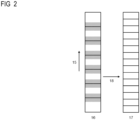
- FIG 2 shows, by way of example, a division (of the setpoint 15) of the burner output and/or the fan speed into ranges 16. If the burner output and/or the fan speed is set and/or regulated in at least one of the ranges 16 during operation, a check is carried out to determine whether a calibration request is pending.
- the burner output and/or the fan speed can be set and/or regulated in at least one of the ranges 16 by controlling a higher-level unit.
- the higher-level unit can be a temperature controller or another unit that adjusts or sets the output of the combustion device.
- the higher-level unit can also be a temperature controller or another unit that regulates the output of the combustion device.
- the higher-level unit can be fully or partially integrated into the control and/or regulating device 10. In a compact embodiment, the higher-level unit is fully integrated into the control and/or regulating device 10. This integration also avoids additional components and additional signal paths. This avoids failures that may occur due to the additional components or the additional signal paths.
- an attempt is made to perform a calibration.
- an attempt is made to perform a calibration that compensates for the aging of the at least one combustion sensor 7.
- an attempt is made to perform a calibration that compensates for the effects of the aging of the at least one combustion sensor 7 on the operation of the combustion device.
- range 16 is marked. By setting at least one flag, range 16 is marked. As long as the flag is set, no new calibration is performed.
- a flag may comprise a bit, in particular an electronic bit. Furthermore, a flag may be a bit, in particular an electronic bit. Within the scope of the present disclosure, a flag in a memory may comprise a bit, in particular an electronic bit, in the memory. Furthermore, a flag in a memory may be a bit, in particular an electronic bit, in the memory.
- At least one flag can be set as a marker in a memory of the control and/or regulating device 10.
- the control and/or regulating device 10 can preferably comprise a memory area.
- the memory area comprises at least one flag for each of the areas 16.
- the memory area can comprise redundant flags such as checksums and/or parity bits.
- the checksums and/or parity bits are each functions of the bits for each of the areas 16. The redundant bits prevent erroneous markings in the memory of the control and/or regulating device 10.
- the marking expires after a specified period of time.
- This period specifies the time after which a new calibration is required. This means that the calibration is valid for the specified period of time.
- This period of time is preferably defined in the control and/or regulating device 10. This period of time can also be parameterized in the control and/or regulating device 10.
- FIG 2 shows hatching.
- the hatching clearly shows that the regions 16 can overlap.
- the regions 16 are non-overlapping.
- a calibration for a set and/or adjusted range 16 cannot be successfully completed.
- the combustion device does not sufficiently dissipate the heat generated during calibration or cannot sufficiently dissipate it.
- at least one range 16 is locked for calibration for a specified period. Supervision tests are still possible during this locked period.
- the lock can be triggered, for example, by an additional locking mark for the at least one area 16 in the memory of the control and/or regulation device 10. This means that no calibration is performed as long as the locking mark for the at least one area 16 is stored in the memory.
- the locking can be performed, in particular, using a locking mark in the non-volatile memory of the control and/or regulation device 10. This means that no calibration is performed as long as the locking mark for the at least one area 16 is stored in the non-volatile memory.
- the aforementioned blocking mark is a third mark, for example, a third electronic mark, in the memory of the control and/or regulation device 10.
- the blocking mark can be a third mark, for example, a third electronic mark, in a non-volatile memory of the control and/or regulation device 10.
- a further period of time until a calibration is carried out is defined and/or parameterized in the control and/or regulating device 10.
- the further period of time until a calibration is carried out is generally not identical to the period of time after which a marking of a range 16 expires.
- the further period of time until a calibration is completed is generally not identical to the period of time after which a marking of a range 16 expires.
- a range 16 (of the setpoint 15) of the burner output and/or fan speed can be set or adjusted.
- the marking of that range 16 has expired, and no calibration has been carried out during the further period of time until a calibration is carried out.
- the marking of that range 16 has expired, and no calibration has been carried out during the further period of time until a calibration is completed.
- a supervision test is requested.
- the control and/or regulating device 10 can request a supervision test.
- the modulation range 15 of the burner output and/or the fan speed is also divided into ranges 17.
- the burner output and/or the fan speed of the combustion device can be divided into ranges 17.
- the ranges 17 for the supervision test are not identical to the ranges 16 for calibration.
- the ranges 17 for the supervision test are identical to the ranges 16 for calibration. This embodiment reduces the memory requirement in the control and/or regulating device 10. The reduction in memory requirement arises from the fact that separate memory for the ranges 16 for calibration and memory for the ranges 17 for the supervision test do not have to be provided.
- control and/or regulating device 10 may comprise a memory area.
- the memory area comprises at least one flag for each of the areas 17.
- the memory area may comprise redundant bits such as checksums and/or parity bits.
- the checksums and/or parity bits are functions of the bits for each of the areas 17.
- the redundant bits prevent incorrect markings in the memory of the control and/or regulating device 10.
- Those areas 16 in which no successful calibration could be performed determine the areas 17 for a supervision test request. This determination is made via an assignment 18.
- each at least one area 16 in which no successful calibration could be performed can be mapped to at least one area 17 for a supervision test by the assignment 18. This means that for each at least one area 16 in which no calibration could be performed, there exists an area for a supervision test. In a specific embodiment, for each area 17 for a supervision test, there is exactly one area 16 due to the assignment 18.
- the at least one area 17 can be marked to request a supervision test.
- the control and/or regulating device 10 can comprise a memory and set a flag in the memory to mark at least one area 17.
- the control and/or regulating device 10 can comprise a memory and set a flag in the memory to mark at least one area 17 to request the supervision test.
- the supervision test preferably lasts 20 seconds or less. More preferably, the supervision test lasts 10 seconds or less. Ideally, the supervision test lasts 5 seconds or less. Generally, the duration of a supervision test is shorter or significantly shorter than the duration of a calibration. A short supervision test does not interfere, or only marginally interferes, with the operation of the combustion device. In particular, heat generated during the supervision test can be effectively dissipated.
- control and/or regulating device 10 can comprise a memory and, as a result of the supervision test being passed, can delete a flag for marking an area 17 in the memory.
- a further time period for reversing the deletion of the supervision test request is defined and/or parameterized in the control and/or regulation device 10.
- a further time period for re-marking at least one area 17 after a passed supervision test can be defined and/or parameterized in the control and/or regulation device 10. This means that after this further time period for reversing the deletion and/or for re-marking, a drift of the combustion sensor 7 should be re-tested. The re-test takes place, for example, using another supervision test.
- a calibration has been successfully performed during the additional time period for undoing the deletion and/or for re-marking. Such a successful calibration is possible because a calibration request is still pending even if the supervision test has been passed. In this case, a supervision test is blocked until the successfully performed calibration loses its validity.
- the control and/or regulating device 10 checks, based on the assignment 18, whether at least one area 16 for calibration exists for the area 17 in question for a supervision test. It is now possible that a calibration request exists for this at least one area 16 and the calibration is valid. This means that the at least one area 16 is marked accordingly. In one embodiment, a flag for marking the at least one area 16 is set in a memory of the control and/or regulating device 10.
- no deletion of a supervision test request is now reversed in the assigned area 17 for the supervision test.
- no deletion of a supervision test request is reversed in the assigned areas 17 for the supervision test. The deletion of the supervision test request is not reversed even if the time period for reversing the deletion of the supervision test request has expired.
- the at least one assigned area 17 is not marked again for a supervision test request. The at least one area 17 is not marked again for a supervision test request even if the time period for reversing the deletion has expired.
- the combustion device and/or its control and/or regulation device 10 requests a burner output and/or a fan speed for which no valid calibration exists.
- the at least one range 16 is accordingly unmarked.
- the marking of the at least one range 16 may have expired after the specified period of time. The further time until a calibration is carried out has also expired.
- the control and/or regulation device 10 now determines one or more ranges 17 based on the assignment 18 and marks this or these ranges 17.
- Ranges 16 and 17 are normally different from one another, but in a special embodiment they may also be identical. In particular, ranges 16 and 17 are normally different from one another in pairs, but in a special embodiment they may also be identical.
- the control and/or regulating device 10 is preferably also designed to request a burner output and/or a fan speed.
- the control and/or regulating device 10 can be designed to set and/or regulate a burner output and/or a fan speed.
- the burner output is, for example, a burner output of the combustion device.
- the fan speed is, for example, a fan speed of the combustion device.
- the fan speed is preferably a fan speed of the fan 3 of the combustion device.
- control and/or regulating device 10 is designed to check whether a first marking in the form of a first set flag, for example a first electronic marking in the form of a first set flag, is stored in the memory of the control and/or regulating device 10 for the one or more first regions 16.
- control and/or regulating device 10 comprises a non-volatile memory and is designed to check whether a first marking in the form of a first set flag, for example a first electronic marking in the form of a first set flag, is stored in the memory of the control and/or regulating device 10 for the one or more first regions 16. Areas 16, a first marking, for example a first electronic marking, is stored in the non-volatile memory of the control and/or regulating device 10.
- control and/or regulating device 10 comprises a non-volatile memory and is designed to check whether a first marking in the form of a first set flag, for example a first electronic marking in the form of a first set flag, is stored in the non-volatile memory of the control and/or regulating device 10 for the one or more first areas 16.
- control and/or regulating device 10 is designed to check whether the memory is free of a first marking in the form of a first (set) flag, in particular is free of a first electronic marking in the form of a first (set) flag, for the one or more first areas 16.
- control and/or regulating device 10 can comprise a non-volatile memory and be designed to check whether the non-volatile memory is free of a first marking, in particular is free of a first electronic marking, for the one or more first areas 16.
- control and/or regulating device 10 comprises a clock, such as an internal clock based on complementary metal oxide semiconductors.
- the time can also be transmitted externally to the control and/or regulating device 10.
- the control and/or regulating device 10 is then configured to determine a current time based on the clock.
- the control and/or regulating device 10 comprises an internal clock and is configured to determine a current time, in particular the current operating time, based on the internal clock of the control and/or regulating device 10.
- the control and/or regulating device 10 comprises an internal clock based on complementary metal-oxide semiconductors and is configured to determine a current time, in particular the current operating time, based on the internal clock, which is based on complementary metal-oxide semiconductors and is comprised by the control and/or regulating device 10.
- control and/or regulating device 10 is configured to determine a point in time until a calibration is performed as a function of a time period until a calibration is performed.
- the time period until a calibration is performed can be Memory of the control and/or regulating device 10.
- the time until a calibration is carried out can be stored in particular in a non-volatile memory of the control and/or regulating device 10.
- control and/or regulating device 10 is designed to store or set a second marking in the form of a second set flag, in particular a second electronic marking in the form of a second set flag, for the second area in the memory of the control and/or regulating device 10.
- control and/or regulating device 10 comprises a non-volatile memory and is designed to store or set a second marking, in particular a second electronic marking, for the second area in the non-volatile memory of the control and/or regulating device 10.
- control and/or regulating device 10 comprises a non-volatile memory and is designed to store or set a second marking in the form of a second set flag, in particular a second electronic marking in the form of a second set flag, for the second area in the non-volatile memory of the control and/or regulating device 10.
- the one or more first regions 16 are generally different from the at least one second region 17. In a specific embodiment, the one or more first regions 16 overlap with the at least one second region 17. In another specific embodiment, the one or more first regions 16 coincide with the at least one second region 17.
- FIG 3 The implementation of a supervision test is based on FIG 3 illustrated.
- the FIG 3 The constellation shown indicates no drift of the combustion sensor 7. Therefore, the corresponding supervision test is passed.
- the one or more first signals are sent from the control and/or regulating device 10 to a drive of the fan 3.
- the mean value is preferably an arithmetic mean calculated as a function of the lower limit of the speed of the fan 3 and the upper limit of the speed of the fan 3.
- the mean value is a geometric mean. The geometric mean is calculated as a function of the lower limit of the speed of the fan 3 and the upper limit of the speed of the fan 3.
- the one or more second signals are sent from the control and/or regulating device 10 to a drive of the fan 3.
- the one or more first signals to the fan 3 are usually different from the one or more second signals to the fan 3. However, it may happen that the one or more first signals to the fan 3 coincide with the one or more second signals to the fan 3.
- the characteristic curve 21 indicates an assignment of the signal 19 of the combustion sensor 7 to the air ratio 20. Conversely, the characteristic curve 21 assigns an air ratio 20 to a signal 19 of the combustion sensor 7. Preferably, the latter assignment is unambiguous.
- the characteristic curve 21 can indicate an assignment of the measured value from the signal 19 of the combustion sensor 7 to the air ratio 20. Conversely, the characteristic curve 21 assigns an air ratio 20 to a signal 19 of the combustion sensor 7 assigned. Preferably, the latter assignment is unambiguous.
- the assignment of the measured value from the signal 19 of the combustion sensor 7 to the air ratio 20 can be performed, for example, by the control and/or regulating device 10.
- the assignment of the air ratio 20 to the measured value from the signal 19 of the combustion sensor 7 can be performed, for example, by the control and/or regulating device 10.
- the characteristic curve 21 can indicate an assignment of the measured value from the signal 19 of the combustion sensor 7 to the air ratio 20.
- the characteristic curve 21 assigns an air ratio 20 to a signal 19 of the combustion sensor 7.
- the latter assignment is preferably unambiguous.
- the assignment of the measured value from the signal 19 of the combustion sensor 7 to the air ratio 20 can be carried out, for example, by the control and/or regulating device 10.
- the assignment of the air ratio 20 to the measured value from the signal 19 of the combustion sensor 7 can be carried out, for example, by the control and/or regulating device 10.
- the signal value 22 of the combustion sensor 7 corresponds to the air ratio value 23.
- the measured value obtained from the signal value 22 of the combustion sensor 7 corresponds to the air ratio value 23.
- the air ratio value 23 is thus adjusted with the aid of the control and/or regulating device 10.
- the air ratio value 23 is adjusted with the aid of the control and/or regulating device 10 using the measured value obtained from the signal value 22 of the combustion sensor 7.
- control and/or regulating device 10 regulates to a signal value 24 of combustion sensor 7.
- control and/or regulating device 10 can re-regulate to a setpoint 24 of combustion sensor 7.
- control parameters in the control and/or regulating device 10 can also be changed during this time.
- control parameters of a proportional and/or integral controller of the control and/or regulating device 10 can be changed.
- control parameters of a proportional and/or integral and/or derivative controller of the control and/or regulating device 10 can be changed.
- a new point 25, 24 is found along the characteristic curve 21 for the new setpoint 24 for the signal of the combustion sensor 7.
- the gradient at the new point 25, 24 is similar to the gradient at the point 23, 22.
- the control and/or regulating device 10 quickly reaches the new point 25, 24 and remains stable there.
- the control and/or regulating device 10 reaches the new point 25, 24 within ten seconds and remains stable there.
- the control and/or regulating device 10 reaches the new point 25, 24 within five seconds. Rapid regulation to the new point 25, 24 enables a timely end to the supervision test. This increases the probability that the supervision test can be carried out successfully.
- a stable regulation of the new points 25 and 24 is an indication that the supervision test has been passed.
- a stable regulation of the new points 25 and 24 by the control and/or regulation device 10 is an indication that the supervision test has been passed.
- reaching points 25, 24 indicates that the supervision test has been passed.
- this also applies to reaching a specified range around points 25, 24.
- this applies to reaching a specified range, for example, a specified tolerance range, around the modified, particularly increased, target value 24.
- a marking of at least one area 17 is deleted and/or removed as a result of the supervision test being passed.
- an electronic marking of at least one area 17 is deleted and/or removed.
- at least one area 17 is electronically marked in the form of a flag in the memory of the control and/or regulating device 10, that flag can be deleted.
- the memory of the control and/or regulating device 10 is a non-volatile memory.
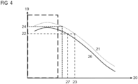
- FIG 4 illustrates a supervision test that is not passed. This means that the supervision test consists of FIG 4 leads to an incorrect result.
- the one or more first signals are sent from the control and/or regulating device 10 to a drive of the fan 3.
- the mean value is preferably an arithmetic mean calculated as a function of the lower limit of the speed of the fan 3 and the upper limit of the speed of the fan 3.
- the mean value is a geometric mean. The geometric mean is calculated as a function of the lower limit of the speed of the fan 3 and the upper limit of the speed of the fan 3.
- the one or more second signals are sent from the control and/or regulating device 10 to a drive of the fan 3.
- the one or more first signals to the fan 3 are usually different from the one or more second signals to the fan 3. However, it may happen that the one or more first signals to the fan 3 coincide with the one or more second signals to the fan 3.
- the example in FIG 4 is based on a drifted and/or aged combustion sensor 7.
- the sensor signal 19 reaches the value 22, the value 23 of the air ratio ⁇ is not reached. Instead, the value 27 of the air ratio ⁇ is reached due to the shifted characteristic curve 26.
- the value 23 of the air ratio ⁇ is not reached. Instead, the value 27 of the air ratio ⁇ is reached with that measured value due to the characteristic curve 26.
- the characteristic curve 26 represents the course of the sensor signal 19 over the air ratio 20 for the drifted and/or aged combustion sensor 7.
- the characteristic curve 26 represents the course of a measured value over the air ratio 20 for the drifted and/or aged combustion sensor 7.
- the measured value is obtained from the sensor signal 19 by signal processing.
- the signal processing is carried out, for example, using the device 10 for control and/or regulation.
- the adjusted value of 27 of the air ratio ⁇ in normal operation is different from the required value of 23 of the air ratio ⁇ .
- the adjusted value of 27 of the air ratio ⁇ due to drift and/or aging is smaller than the required value of 23 of the air ratio ⁇ .
- Such a change can result in critical operation. For example, increased carbon monoxide emissions can occur during critical operation.
- drift is corrected by calibration.
- the shorter supervision test can reveal the drift.
- control and/or regulating device 10 attempts to regulate to a signal value 24 of combustion sensor 7.
- control and/or regulating device 10 can attempt to regulate to a measured value that is assigned to signal value 24 of combustion sensor 7.
- no value of the air ratio ⁇ can be found for a signal value of 24 due to the characteristic curve 26. This means that an attempt to control to a setpoint 24 based on the characteristic curve 26 will result in an error. Due to the characteristic curve 26, that signal value is reached at less than one value of the air ratio ⁇ . In a software implementation, an attempt to assign the value 24 (control to the value 24) can lead to an exception.
- the specified period of time can be, for example, ten seconds or less.
- the specified period of time can also be five seconds or less.
- a short specified period of time prevents overheating of the combustion device or its components.
- the predefined value is ideally a minimum value.
- that signal 19 of combustion sensor 7 may be smaller than a signal 22 of combustion sensor 7 from normal operation.
- that signal may be smaller than a signal 22 from normal operation by a predefined difference.
- that signal 19 of combustion sensor 7 may be smaller than a signal 22 of combustion sensor 7 from normal operation by a predefined factor.
- a measured value obtained from the signal 19 of the combustion sensor 7 may be smaller than a corresponding measured value from normal operation.
- that measured value may be smaller than a corresponding measured value from normal operation by a predetermined difference.
- that measured value may be smaller than a corresponding measured value from normal operation by a predetermined factor.
- a marking of at least one area 17 is not deleted and/or removed. This means that the at least one area 17 remains marked.
- an electronic marking of an area 17 is not deleted and/or removed. This means that the at least one area 17 remains electronically marked.
- the memory of the control and/or regulating device 10 is a non-volatile memory.
- a supervision test with an incorrect result is an indication of a critically drifted and/or aged combustion sensor 7.
- the combustion device may be shut down. Recommissioning is performed by trained personnel. Recommissioning may require replacement of the combustion sensor 7 of the combustion device.
- several supervision tests with faulty results are an indication of a critically drifted and/or aged combustion sensor 7.
- two, five or ten supervision tests with faulty results each can be an indication of a critically drifted and/or aged combustion sensor 7.
- the probability of a false indication of a critically drifted and/or aged combustion sensor 7 decreases with the number of supervision tests with faulty results.
- the combustion device may be taken out of operation. Recommissioning is performed by trained personnel. Recommissioning may require replacement of the combustion sensor 7 of the combustion device.
- the first marker in the memory of the device (10) comprises a first electronic marker in the memory of the device (10).
- the first marker in the memory of the device (10) can be a first electronic marker in the memory of the device (10).
- the device (10) is configured to generate a target value (24) from the target value that is increased by a predetermined amount. In another embodiment, the device (10) is configured to generate a target value (24) from the target value that is increased by a predetermined factor.
- the air actuator (3) By generating a first air control signal and outputting it to the air actuator (3), the air actuator (3) is controlled and/or regulated so that the fan speed remains constant.
- the present disclosure further includes one of the aforementioned devices (10), wherein the device (10) is designed to generate a changed fuel control signal as a function of the changed, in particular increased, setpoint value (24) and to output it to the fuel actuator (5) while maintaining the first air control signal.
- the predetermined minimum value is preferably stored in the memory of the device (10), and the device (10) is configured to load the predetermined minimum value from the memory of the device (10).
- the predetermined minimum value is ideally stored in a non-volatile memory of the device (10), and the device (10) is configured to load the predetermined minimum value from the non-volatile memory of the device (10).
- the present disclosure further relates to one of the aforementioned devices, wherein the device (10) is designed: to generate a modified fuel control signal after the burner output has been requested or after the fan speed has been requested, while maintaining the first air control signal using the second control parameters and incorporating the at least one combustion sensor (7) by controlling to the modified, in particular increased, setpoint (24) and to output it to the fuel actuator (5).
- the at least one combustion sensor (7) can be incorporated into the control system and/or taken into account during the control system by the combustion sensor (7) providing a response signal for the control system.
- the device (10) is preferably configured to load the first and second control parameters from the memory of the device (10).
- the device (10) can be configured to load the first and second control parameters from a non-volatile memory of the device (10).
- the first control parameters comprise first proportional and first integral control parameters. In a specific embodiment, the first control parameters are first proportional and first integral control parameters. In one embodiment, the second control parameters comprise second proportional and second integral control parameters. In a specific embodiment, the second control parameters are second proportional and second integral control parameters.
- the second proportional control parameter is preferably greater than the first proportional control parameter. This enables faster adjustment to the changed, particularly increased, setpoint (24).
- the first control parameters comprise first proportional and first integral and first derivative control parameters.
- the first control parameters are first proportional and first integral and first derivative control parameters.
- the second control parameters comprise second proportional and second integral and second derivative control parameters.
- the second control parameters are second proportional and second integral and second derivative control parameters.
- the second proportional control parameter is preferably greater than the first proportional control parameter. This enables faster adjustment to the changed, in particular increased, setpoint (24).
- the second marker in the memory of the device (10) comprises a second electronic marker in the memory of the device (10).
- the second marker in the memory of the device (10) can be a second electronic marker in the memory of the device (10).
- the at least one second region (17) is a second region (17). In a specific embodiment, the at least one second region (17) is precisely a second region (17).
- the present disclosure further relates to one of the aforementioned devices (10), wherein the device (10) is designed to recognize a passed supervision test based on the evaluation if at least one of the first actual values from the test operation is greater than the predetermined minimum value.
- the device (10) is configured to detect a passed supervision test based on the evaluation if all initial actual values from the test operation are greater than the specified minimum value. This embodiment allows for more reliable detection of a passed supervision test.
- the device (10) is configured to recognize a passed supervision test based on the evaluation if all initial actual values from the test operation lie within a predetermined target range around a target value. Furthermore, the device (10) can be configured to recognize a passed supervision test based on the evaluation, if all initial actual values from the test operation lie within a predetermined tolerance band around the modified, in particular increased, target value (24).
- target and tolerance bands also allow for more reliable detection of a passed supervision test.
- the present disclosure further relates to one of the aforementioned devices (10) having passed the supervision test, wherein the device (10) is designed to delete the second marking for the at least one second area (17) from the memory of the device (10) as a result of the supervision test being passed.
- the device (10) is designed to remove the second marking for the at least one second area (17) from the memory of the device (10) as a result of the supervision test being passed. Furthermore, the device (10) can be designed to delete and/or remove a second electronic marking for the at least one second area (17) from the memory of the device (10) as a result of the supervision test being passed. In a further embodiment, the device (10) is designed to delete and/or remove the second marking for the at least one second area (17) from the memory of the device (10) in response to the supervision test being passed. Furthermore, the device (10) can be designed to delete and/or remove a second electronic marking for the at least one second area (17) from the memory of the device (10) in response to the supervision test being passed.
- the present disclosure also relates to one of the aforementioned devices (10) having passed the supervision test and first control parameters, wherein the device (10) is designed: to control the fuel actuator (5) after the evaluation by comparison with the specified minimum value using the first control parameters.
- the present disclosure further relates to one of the aforementioned devices (10) with first and second control parameters and a passed supervision test, wherein the device (10) is designed: to control the fuel actuator (5) (based on a fuel control signal) after the evaluation by comparison with the predetermined minimum value using the first control parameters and including the at least one combustion sensor (7).
- the at least one combustion sensor (7) can be included in the control and/or taken into account during the control by the combustion sensor (7) providing a response signal for the control.
- the device (10) is designed to generate fuel control signals for normal operation after the evaluation by comparison with the predetermined minimum value by control using the first control parameters and to output the fuel control signals for normal operation to the fuel actuator (5).
- the device (10) is ideally configured to load the first control parameters from the memory of the device (10).
- the device (10) can be configured to load the first control parameters from a non-volatile memory of the device (10).
- the first control parameters comprise first proportional and first integral control parameters. In a specific embodiment, the first control parameters are first proportional and first integral control parameters. In one embodiment, the second control parameters comprise second proportional and second integral control parameters. In a specific embodiment, the second control parameters are second proportional and second integral control parameters.
- the second proportional control parameter is preferably larger than the first proportional control parameter. This ensures stable operation and/or stable control after passing the supervision test.
- the first control parameters comprise first proportional and first integral and first derivative control parameters. In a specific embodiment, the first control parameters are first proportional and first integral and first derivative control parameters. In one embodiment, the second control parameters comprise second proportional and second integral and second derivative control parameters. In a specific embodiment, the second control parameters are second proportional and second integral and second derivative control parameters. The second proportional control parameter is preferably greater than the first proportional control parameter. This ensures stable operation and/or stable control after the supervision test has been passed.
- the present disclosure also relates to one of the aforementioned devices (10), wherein the device (10) is designed to carry out a supervision test with to detect an incorrect result if at least one of the first actual values from the test operation is smaller than the specified minimum value.
- the present disclosure further relates to one of the aforementioned devices (10), wherein the device (10) is designed to detect a supervision test with an erroneous result based on the evaluation if all first actual values from the test operation are smaller than the predetermined minimum value.
- the present disclosure further relates to one of the aforementioned devices (10), wherein the device (10) is configured to detect a supervision test with an incorrect result based on the evaluation if at least one of the first actual values from the test operation is smaller than the predefined minimum value or greater than a predefined maximum value. Furthermore, the device (10) can be configured to detect a supervision test with an incorrect result based on the evaluation if at least one of the first actual values from the test operation falls below the predefined minimum value or exceeds a predefined maximum value.
- the present disclosure further relates to one of the aforementioned devices (10), wherein the device (10) is configured to detect a supervision test with an incorrect result based on the evaluation if at least all of the first actual values from the test operation are smaller than the predefined minimum value or greater than a predefined maximum value. Furthermore, the device (10) can be configured to detect a supervision test with an incorrect result based on the evaluation if all of the first actual values from the test operation are below the predefined minimum value or exceed a predefined maximum value.
- a flame signal that is zero apart from noise is essentially zero.
- noise is caused, for example, by active and passive elements in a flame signal evaluation circuit.
- a flame signal that is zero apart from any quiescent currents is essentially zero.
- active elements such as operational amplifiers have such quiescent currents.
- Flame sensors for combustion devices are disclosed, among others, in the European patent EP3339736B1, which was published on 10 April 2019 Flame sensors for combustion devices are further disclosed in the European patent EP3663646B1, which was published on 2 June 2021 has been granted.
- the flame sensor is preferably different from the at least one combustion sensor (7).
- the flame sensor can be an optical flame sensor or comprise an optical flame sensor.
- the flame sensor is ideally communicatively connected to the device (10). An additional flame sensor for detecting a flame loss enables redundant detection of a supervision test with an incorrect result and thus improves the reliability of the combustion device.
- the flame sensor itself can also be identical to the combustion sensor. This applies, for example, to an ionization electrode, an ionization sensor, or a temperature sensor.
- the present disclosure further relates to one of the aforementioned devices (10) with a supervision test with an erroneous result and with a second marking, wherein the device (10) is designed to retain the second marking for the at least one second area (17) in the memory of the device (10) as a result of the supervision test with an erroneous result.
- the device (10) can be designed to generate a second electronic marking for the at least one second area (17) in the Memory of the device (10).
- the device (10) is configured to maintain the second marking for the at least one second area (17) in the memory of the device (10) in response to the supervision test with an erroneous result.
- the device (10) can be configured to maintain a second electronic marking for the at least one second area (17) in the memory of the device (10) in response to the supervision test with an erroneous result.
- Closing and/or locking the fuel actuator (5) serves to ensure the safety of the combustion device.
- the present disclosure further relates to one of the aforementioned devices (10), wherein the device (10) is designed to deposit or set one or the first marking for the at least one first region (16) after a successfully performed calibration for one or the at least one first region (16).
- the present disclosure further relates to one of the aforementioned devices (10), wherein the device (10) is designed to deposit or set one or the first marking for the at least one first region (16) after a successfully performed calibration.
- the carbon monoxide sensor (CO sensor) is located in the chimney (8).
- the carbon monoxide sensor is a carbon monoxide sensor.
- the present disclosure relates to one of the aforementioned combustion devices with carbon monoxide sensor, wherein the device (10) is designed: to generate combined values by weighting the signals from the first sensor and by weighting the signals from the second sensor.
- the present disclosure further relates to one of the aforementioned combustion devices with carbon monoxide sensor, wherein the device (10) is designed: to generate combined values by weighting the one or more first combustion sensor signals of the first sensor of the at least one combustion sensor (7) and by weighting the one or more second combustion sensor signals of the second sensor of the at least one combustion sensor (7).
- the device (10) can also be configured to detect a passed supervision test or a supervision test with an incorrect result as a function of at least one of the combined values.
- a passed supervision test or a supervision test with an incorrect result is detected by comparison with a threshold value ⁇ .
- the predetermined maximum value is preferably stored in the memory of the device (10), and the device (10) is configured to load the predetermined maximum value from the memory of the device (10).
- the predetermined maximum value is ideally stored in a non-volatile memory of the device (10), and the device (10) is configured to load the predetermined maximum value from the non-volatile memory of the device (10).
- Closing and/or locking the fuel actuator (5) serves to ensure the safety of the combustion device.
- the fuel actuator (5) comprises a movable valve actuator and closes by moving the valve actuator to a closed position. The fuel actuator (5) is then in the closed state.
- the at least one limit value is precisely one limit value. In one embodiment, the at least one limit value is precisely one predefined limit value.
- the present disclosure also teaches one of the aforementioned devices (10) including at least one limit value in the form of a predetermined minimum value, wherein the device (10) is designed to recognize a passed supervision test based on the evaluation of the first actual values from the test operation if at least one of the first actual values from the test operation is greater than the predetermined minimum value.
- the present disclosure also teaches one of the aforementioned devices (10) including at least one limit value in the form of a predetermined minimum value, wherein the device (10) is designed to recognize a passed supervision test based on the evaluation of the first actual values from the test operation if all first actual values from the test operation are greater than the predetermined minimum value.
- the present disclosure further teaches one of the aforementioned devices (10) including at least one limit value in the form of a limit value from a predetermined band, wherein the device (10) is designed to recognize a passed supervision test based on the evaluation of the first actual values from the test operation if at least one of the first actual values from the test operation is smaller than the upper limit value of the band and larger than the lower limit value of the predetermined band.
- the present disclosure further teaches one of the aforementioned devices (10) including at least one limit value in the form of a limit value from a predetermined band, wherein the device (10) is designed to recognize a passed supervision test based on the evaluation of the first actual values from the test operation if all first actual values from the test operation are smaller than the upper limit value of the band and larger than the lower limit value of the predetermined band.
- the present disclosure also teaches one of the aforementioned devices (10) including at least one limit value in the form of a predetermined minimum value, wherein the device (10) is designed to detect a supervision test with an incorrect result based on the evaluation if at least one of the first actual values from the test operation is smaller than the predetermined minimum value.
- the present disclosure also teaches one of the aforementioned devices (10) including at least one limit value in the form of a predetermined minimum value, wherein the device (10) is designed to detect a supervision test with an incorrect result based on the evaluation of the first actual values from the test operation if all first actual values from the test operation are smaller than the predetermined minimum value.
- the present disclosure further teaches one of the aforementioned devices (10) including at least one limit value in the form of a limit value from a predetermined band, wherein the device (10) is designed to detect a supervision test with an erroneous result based on the evaluation if at least one of the first actual values from the test operation is greater than the upper limit value of the band or is smaller than the lower limit value of the predetermined band.
- the present disclosure further teaches one of the aforementioned devices (10) including at least one limit value in the form of a limit value from a predetermined band, wherein the device (10) is designed to detect a supervision test with an incorrect result based on the evaluation if all first actual values from the Test operation is greater than the upper limit of the band or less than the lower limit of the specified band.
- the present disclosure also teaches one of the aforementioned devices (10), wherein the device (10) is designed: to check whether a first marking is stored in the memory of the device (10) for the at least one first area (16), wherein the first marking indicates a valid calibration for the at least one first area (16).
- the present disclosure further teaches one of the aforementioned devices (10), wherein the device (10) is designed: to check whether a first marking is stored in the memory of the device (10) for the at least one first area (16), wherein the first marking indicates a successfully performed calibration for the at least one first area (16).
- the aforementioned test operation is a supervision test operation.
- the present disclosure further relates to one of the aforementioned devices (10), wherein the air actuator (3) of the combustion device is designed to influence a supply quantity (4) of air to the combustion chamber (2) as a function of an air control signal, and wherein the fuel actuator (5) of the combustion device is designed to influence a supply quantity (6) of fuel to the combustion chamber (2) as a function of a fuel control signal.
- the present disclosure further relates to one of the aforementioned combustion devices, wherein the air actuator (3) of the combustion device is designed to influence a supply quantity (4) of air to the combustion chamber (2) as a function of an air control signal, and wherein the fuel actuator (5) of the combustion device is designed to influence a supply quantity (6) of fuel to the combustion chamber (2) as a function of a fuel control signal.
- the present disclosure further relates to one of the aforementioned devices (10), wherein the limit value is stored in the memory of the device (10).
- the limit value is a predetermined limit value
- the predetermined limit value is stored in the memory of the device (10).
Landscapes
- Engineering & Computer Science (AREA)
- Chemical & Material Sciences (AREA)
- Combustion & Propulsion (AREA)
- Mechanical Engineering (AREA)
- General Engineering & Computer Science (AREA)
- Regulation And Control Of Combustion (AREA)
Priority Applications (1)
| Application Number | Priority Date | Filing Date | Title |
|---|---|---|---|
| EP23205942.8A EP4545854B1 (fr) | 2023-10-25 | 2023-10-25 | Régulation d'un dispositif de combustion |
Applications Claiming Priority (1)
| Application Number | Priority Date | Filing Date | Title |
|---|---|---|---|
| EP23205942.8A EP4545854B1 (fr) | 2023-10-25 | 2023-10-25 | Régulation d'un dispositif de combustion |
Publications (2)
| Publication Number | Publication Date |
|---|---|
| EP4545854A1 true EP4545854A1 (fr) | 2025-04-30 |
| EP4545854B1 EP4545854B1 (fr) | 2025-12-31 |
Family
ID=88558334
Family Applications (1)
| Application Number | Title | Priority Date | Filing Date |
|---|---|---|---|
| EP23205942.8A Active EP4545854B1 (fr) | 2023-10-25 | 2023-10-25 | Régulation d'un dispositif de combustion |
Country Status (1)
| Country | Link |
|---|---|
| EP (1) | EP4545854B1 (fr) |
Citations (8)
| Publication number | Priority date | Publication date | Assignee | Title |
|---|---|---|---|---|
| EP2466204A1 (fr) | 2010-12-16 | 2012-06-20 | Siemens Aktiengesellschaft | Dispositif de réglage pour une installation de brûleur |
| EP3045816A1 (fr) | 2015-01-19 | 2016-07-20 | Siemens Aktiengesellschaft | Dispositif de réglage d'une installation de brûleur |
| EP3339736B1 (fr) | 2016-12-21 | 2019-04-10 | Siemens Aktiengesellschaft | Détection de flamme pour appareils de combustion |
| EP3301364B1 (fr) | 2016-09-30 | 2019-08-07 | Siemens Aktiengesellschaft | Unité de combustion avec un bruleur et un dispositif de mésure de débit d'écoulements turbulents |
| EP3690318A2 (fr) * | 2019-01-29 | 2020-08-05 | Vaillant GmbH | Procédé et dispositif de régulation d'un mélange air-gaz de combustion dans un appareil de chauffage |
| EP3663646B1 (fr) | 2018-12-06 | 2021-06-02 | Siemens Aktiengesellschaft | Système de control de surveillance de flamme |
| EP3988844A1 (fr) * | 2020-10-20 | 2022-04-27 | Viessmann Climate Solutions SE | Installation de chauffage et procédé de fonctionnement d'une installation de chauffage |
| EP4119847A1 (fr) | 2021-07-16 | 2023-01-18 | Siemens Aktiengesellschaft | Dispositif de combustion comprenant un dispositif de régulation |
-
2023
- 2023-10-25 EP EP23205942.8A patent/EP4545854B1/fr active Active
Patent Citations (11)
| Publication number | Priority date | Publication date | Assignee | Title |
|---|---|---|---|---|
| EP2466204A1 (fr) | 2010-12-16 | 2012-06-20 | Siemens Aktiengesellschaft | Dispositif de réglage pour une installation de brûleur |
| EP2466204B1 (fr) | 2010-12-16 | 2013-11-13 | Siemens Aktiengesellschaft | Dispositif de réglage pour une installation de brûleur |
| EP3045816A1 (fr) | 2015-01-19 | 2016-07-20 | Siemens Aktiengesellschaft | Dispositif de réglage d'une installation de brûleur |
| EP3045816B1 (fr) | 2015-01-19 | 2018-12-12 | Siemens Aktiengesellschaft | Dispositif de commande d'une installation de brûleur |
| EP3301364B1 (fr) | 2016-09-30 | 2019-08-07 | Siemens Aktiengesellschaft | Unité de combustion avec un bruleur et un dispositif de mésure de débit d'écoulements turbulents |
| EP3339736B1 (fr) | 2016-12-21 | 2019-04-10 | Siemens Aktiengesellschaft | Détection de flamme pour appareils de combustion |
| EP3663646B1 (fr) | 2018-12-06 | 2021-06-02 | Siemens Aktiengesellschaft | Système de control de surveillance de flamme |
| EP3690318A2 (fr) * | 2019-01-29 | 2020-08-05 | Vaillant GmbH | Procédé et dispositif de régulation d'un mélange air-gaz de combustion dans un appareil de chauffage |
| EP3988844A1 (fr) * | 2020-10-20 | 2022-04-27 | Viessmann Climate Solutions SE | Installation de chauffage et procédé de fonctionnement d'une installation de chauffage |
| EP4119847A1 (fr) | 2021-07-16 | 2023-01-18 | Siemens Aktiengesellschaft | Dispositif de combustion comprenant un dispositif de régulation |
| EP4119847B1 (fr) | 2021-07-16 | 2023-06-14 | Siemens Aktiengesellschaft | Dispositif de combustion comprenant un dispositif de régulation |
Also Published As
| Publication number | Publication date |
|---|---|
| EP4545854B1 (fr) | 2025-12-31 |
Similar Documents
| Publication | Publication Date | Title |
|---|---|---|
| EP2466204B1 (fr) | Dispositif de réglage pour une installation de brûleur | |
| EP1293727B1 (fr) | Appareil de commande d'un brûleur et méthode de réglage | |
| EP0067931A2 (fr) | Méthode et appareil pour la surveillance et le calibrage de sondes à courant limite | |
| DE112014001000T5 (de) | Gasturbinensystem, Steuer- bzw. Regelungseinrichtung und Gasturbinenbetriebsverfahren | |
| EP3299718B1 (fr) | Détection de type de gaz | |
| EP3045816A1 (fr) | Dispositif de réglage d'une installation de brûleur | |
| EP4545854B1 (fr) | Régulation d'un dispositif de combustion | |
| EP3499124A1 (fr) | Composant d'appareil de chauffage et procédé de réglage d'un débit volumétrique de carburant | |
| EP4050258B1 (fr) | Procédé de régulation d'un dispositif de brûleur avec détermination de la puissance à l'aide d'un paramètre de combustible | |
| EP3870899A1 (fr) | Procédé de contrôle d'un capteur de mélange gazeux et d'un capteur d'ionisation dans un appareil de chauffage fonctionnant au gaz combustible | |
| EP4119847B1 (fr) | Dispositif de combustion comprenant un dispositif de régulation | |
| DE102019110977A1 (de) | Verfahren zur Überprüfung eines Gasgemischsensors bei einem brenngasbetriebenen Heizgerät | |
| DE102015225886A1 (de) | Heizgerätesystem und Verfahren mit einem Heizgerätesystem | |
| EP3751200B1 (fr) | Procédé de régulation d'un appareil chauffant à gaz combustible | |
| DE102023212455B3 (de) | Automatisierung anhand Sauerstoffkonzentration | |
| EP4459183B1 (fr) | Procédé de fonctionnement d'un appareil de chauffage, appareil de chauffage et programme informatique | |
| EP4102136B1 (fr) | Procédé de vérification d'un dispositif de surveillance de flammes d'un appareil chauffant, appareil chauffant, programme informatique et support de stockage | |
| DE102020104084A1 (de) | Verfahren zur Überwachung und Regelung eines Prozesses einer Gastherme und Gastherme | |
| DE102021103456A1 (de) | Gastherme sowie Verfahren zur Einstellung eines Brennstoff-Oxidator-Gemisches in Abhängigkeit einer Zusammensetzung des Brennstoffes | |
| EP4435322B1 (fr) | Régulation d'un dispositif de combustion | |
| DE102024103278A1 (de) | Verfahren zum Betreiben eines Heizgerätes, Computerprogramm, Regel- und Steuergerät und Heizgerät | |
| EP4421386B1 (fr) | Procédé de fonctionnement d'un appareil de chauffage, programme informatique, appareil de régulation et de commande et appareil de chauffage | |
| EP4617566A1 (fr) | Commande optimisée d'un dispositif de combustion | |
| DE102024121888A1 (de) | Heizgerät, Verfahren zum Betreiben eines Heizgerätes, Computerprogramm, Regel- und Steuergerät, Heizgerät und Verwendung einer Curie-Temperatur eines Prüfkörpers | |
| EP4215815A1 (fr) | Procédé de fonctionnement d'un appareil de chauffage produisant de la flamme d'une installation de chauffage, programme de com-puter, support de stockage, appareil de commande et utilisation d'un débit d'une installation de chauffage et d'ionisation |
Legal Events
| Date | Code | Title | Description |
|---|---|---|---|
| PUAI | Public reference made under article 153(3) epc to a published international application that has entered the european phase |
Free format text: ORIGINAL CODE: 0009012 |
|
| STAA | Information on the status of an ep patent application or granted ep patent |
Free format text: STATUS: THE APPLICATION HAS BEEN PUBLISHED |
|
| AK | Designated contracting states |
Kind code of ref document: A1 Designated state(s): AL AT BE BG CH CY CZ DE DK EE ES FI FR GB GR HR HU IE IS IT LI LT LU LV MC ME MK MT NL NO PL PT RO RS SE SI SK SM TR |
|
| STAA | Information on the status of an ep patent application or granted ep patent |
Free format text: STATUS: REQUEST FOR EXAMINATION WAS MADE |
|
| 17P | Request for examination filed |
Effective date: 20250603 |
|
| GRAP | Despatch of communication of intention to grant a patent |
Free format text: ORIGINAL CODE: EPIDOSNIGR1 |
|
| STAA | Information on the status of an ep patent application or granted ep patent |
Free format text: STATUS: GRANT OF PATENT IS INTENDED |
|
| RIC1 | Information provided on ipc code assigned before grant |
Ipc: F23N 5/10 20060101AFI20250905BHEP Ipc: F23N 5/12 20060101ALI20250905BHEP |
|
| INTG | Intention to grant announced |
Effective date: 20250930 |
|
| GRAS | Grant fee paid |
Free format text: ORIGINAL CODE: EPIDOSNIGR3 |
|
| GRAA | (expected) grant |
Free format text: ORIGINAL CODE: 0009210 |
|
| STAA | Information on the status of an ep patent application or granted ep patent |
Free format text: STATUS: THE PATENT HAS BEEN GRANTED |
|
| AK | Designated contracting states |
Kind code of ref document: B1 Designated state(s): AL AT BE BG CH CY CZ DE DK EE ES FI FR GB GR HR HU IE IS IT LI LT LU LV MC ME MK MT NL NO PL PT RO RS SE SI SK SM TR |
|
| REG | Reference to a national code |
Ref country code: CH Ref legal event code: F10 Free format text: ST27 STATUS EVENT CODE: U-0-0-F10-F00 (AS PROVIDED BY THE NATIONAL OFFICE) Effective date: 20251231 Ref country code: GB Ref legal event code: FG4D Free format text: NOT ENGLISH |
|
| REG | Reference to a national code |
Ref country code: DE Ref legal event code: R096 Ref document number: 502023002637 Country of ref document: DE |
|
| REG | Reference to a national code |
Ref country code: IE Ref legal event code: FG4D Free format text: LANGUAGE OF EP DOCUMENT: GERMAN |
|
| P01 | Opt-out of the competence of the unified patent court (upc) registered |
Free format text: CASE NUMBER: UPC_APP_0005391_4545854/2026 Effective date: 20260213 |
|
| REG | Reference to a national code |
Ref country code: LT Ref legal event code: MG9D |
|
| PG25 | Lapsed in a contracting state [announced via postgrant information from national office to epo] |
Ref country code: NO Free format text: LAPSE BECAUSE OF FAILURE TO SUBMIT A TRANSLATION OF THE DESCRIPTION OR TO PAY THE FEE WITHIN THE PRESCRIBED TIME-LIMIT Effective date: 20260331 |
|
| PG25 | Lapsed in a contracting state [announced via postgrant information from national office to epo] |
Ref country code: FI Free format text: LAPSE BECAUSE OF FAILURE TO SUBMIT A TRANSLATION OF THE DESCRIPTION OR TO PAY THE FEE WITHIN THE PRESCRIBED TIME-LIMIT Effective date: 20251231 Ref country code: HR Free format text: LAPSE BECAUSE OF FAILURE TO SUBMIT A TRANSLATION OF THE DESCRIPTION OR TO PAY THE FEE WITHIN THE PRESCRIBED TIME-LIMIT Effective date: 20251231 |
|
| PG25 | Lapsed in a contracting state [announced via postgrant information from national office to epo] |
Ref country code: RS Free format text: LAPSE BECAUSE OF FAILURE TO SUBMIT A TRANSLATION OF THE DESCRIPTION OR TO PAY THE FEE WITHIN THE PRESCRIBED TIME-LIMIT Effective date: 20260331 |