EP4545896A1 - Optimiertes wärmespeichersystem und dessen herstellungsverfahren - Google Patents
Optimiertes wärmespeichersystem und dessen herstellungsverfahren Download PDFInfo
- Publication number
- EP4545896A1 EP4545896A1 EP24208401.0A EP24208401A EP4545896A1 EP 4545896 A1 EP4545896 A1 EP 4545896A1 EP 24208401 A EP24208401 A EP 24208401A EP 4545896 A1 EP4545896 A1 EP 4545896A1
- Authority
- EP
- European Patent Office
- Prior art keywords
- plates
- tube
- tubes
- helical fin
- openings
- Prior art date
- Legal status (The legal status is an assumption and is not a legal conclusion. Google has not performed a legal analysis and makes no representation as to the accuracy of the status listed.)
- Granted
Links
Images



Classifications
-
- F—MECHANICAL ENGINEERING; LIGHTING; HEATING; WEAPONS; BLASTING
- F28—HEAT EXCHANGE IN GENERAL
- F28D—HEAT-EXCHANGE APPARATUS, NOT PROVIDED FOR IN ANOTHER SUBCLASS, IN WHICH THE HEAT-EXCHANGE MEDIA DO NOT COME INTO DIRECT CONTACT
- F28D20/00—Heat storage plants or apparatus in general; Regenerative heat-exchange apparatus not covered by groups F28D17/00 or F28D19/00
- F28D20/02—Heat storage plants or apparatus in general; Regenerative heat-exchange apparatus not covered by groups F28D17/00 or F28D19/00 using latent heat
- F28D20/021—Heat storage plants or apparatus in general; Regenerative heat-exchange apparatus not covered by groups F28D17/00 or F28D19/00 using latent heat the latent heat storage material and the heat-exchanging means being enclosed in one container
-
- F—MECHANICAL ENGINEERING; LIGHTING; HEATING; WEAPONS; BLASTING
- F28—HEAT EXCHANGE IN GENERAL
- F28F—DETAILS OF HEAT-EXCHANGE AND HEAT-TRANSFER APPARATUS, OF GENERAL APPLICATION
- F28F1/00—Tubular elements; Assemblies of tubular elements
- F28F1/10—Tubular elements and assemblies thereof with means for increasing heat-transfer area, e.g. with fins, with projections, with recesses
- F28F1/12—Tubular elements and assemblies thereof with means for increasing heat-transfer area, e.g. with fins, with projections, with recesses the means being only outside the tubular element
- F28F1/24—Tubular elements and assemblies thereof with means for increasing heat-transfer area, e.g. with fins, with projections, with recesses the means being only outside the tubular element and extending transversely
- F28F1/32—Tubular elements and assemblies thereof with means for increasing heat-transfer area, e.g. with fins, with projections, with recesses the means being only outside the tubular element and extending transversely the means having portions engaging further tubular elements
-
- F—MECHANICAL ENGINEERING; LIGHTING; HEATING; WEAPONS; BLASTING
- F28—HEAT EXCHANGE IN GENERAL
- F28F—DETAILS OF HEAT-EXCHANGE AND HEAT-TRANSFER APPARATUS, OF GENERAL APPLICATION
- F28F1/00—Tubular elements; Assemblies of tubular elements
- F28F1/10—Tubular elements and assemblies thereof with means for increasing heat-transfer area, e.g. with fins, with projections, with recesses
- F28F1/12—Tubular elements and assemblies thereof with means for increasing heat-transfer area, e.g. with fins, with projections, with recesses the means being only outside the tubular element
- F28F1/24—Tubular elements and assemblies thereof with means for increasing heat-transfer area, e.g. with fins, with projections, with recesses the means being only outside the tubular element and extending transversely
- F28F1/32—Tubular elements and assemblies thereof with means for increasing heat-transfer area, e.g. with fins, with projections, with recesses the means being only outside the tubular element and extending transversely the means having portions engaging further tubular elements
- F28F1/325—Fins with openings
-
- F—MECHANICAL ENGINEERING; LIGHTING; HEATING; WEAPONS; BLASTING
- F28—HEAT EXCHANGE IN GENERAL
- F28F—DETAILS OF HEAT-EXCHANGE AND HEAT-TRANSFER APPARATUS, OF GENERAL APPLICATION
- F28F1/00—Tubular elements; Assemblies of tubular elements
- F28F1/10—Tubular elements and assemblies thereof with means for increasing heat-transfer area, e.g. with fins, with projections, with recesses
- F28F1/12—Tubular elements and assemblies thereof with means for increasing heat-transfer area, e.g. with fins, with projections, with recesses the means being only outside the tubular element
- F28F1/34—Tubular elements and assemblies thereof with means for increasing heat-transfer area, e.g. with fins, with projections, with recesses the means being only outside the tubular element and extending obliquely
- F28F1/36—Tubular elements and assemblies thereof with means for increasing heat-transfer area, e.g. with fins, with projections, with recesses the means being only outside the tubular element and extending obliquely the means being helically wound fins or wire spirals
-
- F—MECHANICAL ENGINEERING; LIGHTING; HEATING; WEAPONS; BLASTING
- F28—HEAT EXCHANGE IN GENERAL
- F28D—HEAT-EXCHANGE APPARATUS, NOT PROVIDED FOR IN ANOTHER SUBCLASS, IN WHICH THE HEAT-EXCHANGE MEDIA DO NOT COME INTO DIRECT CONTACT
- F28D20/00—Heat storage plants or apparatus in general; Regenerative heat-exchange apparatus not covered by groups F28D17/00 or F28D19/00
- F28D2020/0065—Details, e.g. particular heat storage tanks, auxiliary members within tanks
- F28D2020/0078—Heat exchanger arrangements
-
- F—MECHANICAL ENGINEERING; LIGHTING; HEATING; WEAPONS; BLASTING
- F28—HEAT EXCHANGE IN GENERAL
- F28D—HEAT-EXCHANGE APPARATUS, NOT PROVIDED FOR IN ANOTHER SUBCLASS, IN WHICH THE HEAT-EXCHANGE MEDIA DO NOT COME INTO DIRECT CONTACT
- F28D7/00—Heat-exchange apparatus having stationary tubular conduit assemblies for both heat-exchange media, the media being in contact with different sides of a conduit wall
- F28D7/16—Heat-exchange apparatus having stationary tubular conduit assemblies for both heat-exchange media, the media being in contact with different sides of a conduit wall the conduits being arranged in parallel spaced relation
-
- Y—GENERAL TAGGING OF NEW TECHNOLOGICAL DEVELOPMENTS; GENERAL TAGGING OF CROSS-SECTIONAL TECHNOLOGIES SPANNING OVER SEVERAL SECTIONS OF THE IPC; TECHNICAL SUBJECTS COVERED BY FORMER USPC CROSS-REFERENCE ART COLLECTIONS [XRACs] AND DIGESTS
- Y02—TECHNOLOGIES OR APPLICATIONS FOR MITIGATION OR ADAPTATION AGAINST CLIMATE CHANGE
- Y02E—REDUCTION OF GREENHOUSE GAS [GHG] EMISSIONS, RELATED TO ENERGY GENERATION, TRANSMISSION OR DISTRIBUTION
- Y02E60/00—Enabling technologies; Technologies with a potential or indirect contribution to GHG emissions mitigation
- Y02E60/14—Thermal energy storage
Definitions
- This relates to an MCP thermal storage system equipped with a heat transfer fluid exchanger and its assembly method.
- the field of the invention relates to Thermal Storage Systems (TSS) using Phase Change Materials (PCMs); and more particularly, the integration of a heat exchanger with optimized geometry.
- TSS Thermal Storage Systems
- PCMs Phase Change Materials
- the invention will find particular application in urban or rural electricity and heat networks.
- the invention may also find applications in the development of "smart grid” electricity and heat networks, as well as in the interactions between these networks.
- the invention will find its application in particular in urban, rural or industrial heating and/or cooling networks as well as in the storage of solar energy.
- the invention may also find applications in housing, off-grid thermal transport (trucks, boats, etc.) or in the thermal management of on-board (electric batteries) or stationary systems.
- the invention could be implemented following a first application in the substations of heating networks, which present a significant challenge of compactness and offer significant potential replication (several tens of thousands of substations in France).
- the invention could be implemented for the storage of thermal energy from steam by the latent heat of the PCM.
- Heat networks consist of at least one heat source (thermal power plant, thermal solar panels, geothermal source, etc.), a fluid network allowing the transport of calories to users via a heat transfer fluid and possibly a return network.
- Each calorie delivery station corresponds to a heat exchanger allowing the heat transfer from the primary circuit (network connected to the heat source) to a secondary circuit; this second circuit is the property of the subscriber and is crossed by hot water ( ⁇ 100°C).
- This exchanger is the delivery point of the thermal energy, the assembly of exchanger, meter, and the different sets of valves is called: a substation.
- the load of a heat network is very fluctuating, on average over the year the production units operate at 25% of their capacity, in general, the consumption peaks are 3 to 4 times greater than the average annual load. These peaks (morning, evening) represent approximately 30% of the thermal consumption of a typical heating day.
- the backup (and emergency) generators are generally Thermal power plants using heavy fuel oil, natural gas, or coal are polluting and not always cheap. Using a thermal storage system that stores calories while demand is low and reinjects them into the network during consumption peaks could overcome this problem.
- Thermal storage can be achieved by storage by enthalpy of change of state.
- storage occurs via the phase change of a phase-change material. It is the enthalpy of phase change, most often during the change of solid/liquid state, which is stored.
- This energy which is for example absorbed during melting and released during solidification, results from the establishment or rupture of interatomic or intermolecular bonds.
- the charging of the storage system is accompanied by the melting of the storage material, while the discharging is achieved by the solidification of said material.
- the material must be judiciously chosen according to the target temperature of the storage system, so that its melting temperature is within the operating temperature range.
- phase change can occur at constant pressure and temperature. Therefore, the discharge of the stored energy occurs at a constant temperature.
- phase change enthalpy is relatively large compared to the sensible energy change of a material.
- the energy stored in the melting of a block of paraffin (change from 34 to 36°C for Rubitherm ® RT35HC) is equivalent to the energy stored in the same quantity of paraffin if it is heated to 120°C.
- PCM Phase Change Material
- Thermal storage has recently developed around thermodynamic solar power plants in order to compensate for the intermittency of solar resources.
- Today, the The theme of thermal storage also concerns housing, urban heat networks and industry.
- the heat transfer fluid reaches a temperature higher than the melting temperature of the PCM and gives up energy to it, which causes it to melt; during discharge, the heat transfer fluid enters at a temperature lower than the solidification temperature of the PCM and recovers the previously stored energy, which causes the PCM to solidify.
- the tubes are surrounded by circular fins increasing the heat exchange surface or by larger inserts.
- the very low flow rate of the heat transfer fluid in the tubes implies a reduction in heat exchanges which requires the use of solutions such as the addition of internal hydraulic inserts in the tubes, which leads to a significant additional cost resulting from the purchase and assembly of these inserts (which can be carried out by brazing, crimping) in the finned tubes.
- the mechanical stresses generated by the volume expansion of the MCP during its solid-liquid MCP fusion can be particularly strong; if the MCP fusion begins at the bottom of the tank and a layer remains entirely solid above due to dead zones, the pressure rise of the liquid pocket can cause the fins to deform, or even the tank to rupture.
- some of these disadvantages are limited, however the presence of clearance between the fins and the inserts penalizes heat transfer and their implementation remains complex, requiring long and meticulous assembly leading to high costs.
- a thermal storage system (TSS) using a phase change material (PCM) comprising an enclosure intended to contain a PCM and a heat exchanger with a heat transfer fluid arranged at least partially in the enclosure in contact with the PCM, the heat exchanger comprising a bundle of parallel tubes intended to receive a heat transfer fluid, each tube comprising on its surface at least one helical fin wound helically along a longitudinal axis along which the tube extends, characterized in that the system comprises plates each comprising for each tube an opening through which a tube is arranged, and in that the diameter of the openings is less than the maximum external diameter of the helical fin.
- PCM phase change material
- this arrangement allows at least part of the fins to be inserted, at least their end inside the volume formed between the stacked plates and occupied by the MCP.
- the optimization of the arrangement between the plates and the helical fins which can be advantageously in optimum contact allows for improved thermal conductivity.
- the helical fins ensure the possibility of assembling the tubes in the plate openings by screwing.
- This SST design allows the melting or solidification front following the SST use phase (charging or discharging) not to cross a volume occupied only by MCP, presenting low thermal conductivity.
- the SST according to the invention has optimized heat exchange surfaces that are not limited in the type of materials.
- the SST is thus obtained using inexpensive industrial processes and means.
- the invention relates to a method of assembling an SST as described above comprising the following successive steps: - stacking the plates on top of each other by aligning the openings to form a cassette of plates, - inserting the tubes by screwing into the openings of the plates, - assembling the ends of the tubes to collectors, - placing in the enclosure of the heat exchanger.
- ⁇ top' and ⁇ bottom' mean a quality of positioning relative to the SST or an element of the SST when the latter is functionally installed, the ⁇ top' being oriented away from the ground and the ⁇ bottom' being oriented towards the ground.
- the upper end is at the top and the lower end is at the bottom.
- the longitudinal axis is the axis parallel to the main direction of extension.
- the transverse axis is a direction perpendicular to a longitudinal direction.
- a transverse section is a section perpendicular to the longitudinal axis.
- Thickness is usually measured in a direction perpendicular to the principal plane of extension.
- the expression “A and/or B” means (A), (B), or (A and B).
- the expression “A, B, and/or C” means (A), (B), (C), (A and B), (A and C), (B and C), or (A, B and C).
- the SST 100 according to the invention comprises an enclosure 107 and an exchanger.
- the enclosure 107 is typically cylindrical in shape, the walls of which are formed from a metallic material resistant to pressure and temperature variations.
- the enclosure 107 is made of structural carbon steel. Typical grades for a pressure enclosure are P235GH, P265GH, P355GH. If there is a risk of oxidation or corrosion, austenitic stainless steels 304, 316 may be used.
- the enclosure may be made in a single piece, in two welded half-cylinders, or by superimposing shells.
- Enclosure 107 is configured to receive an MCP.
- the MCP is placed directly in enclosure 107 and the exchanger plunges into said MCP.
- the enclosure 107 contains at least one PCM.
- Mixtures of PCMs may be used. In the remainder of the description, the reference to a PCM is not limiting. Different PCMs may be used, in particular solid/solid transition PCMs or preferably solid/liquid transition PCMs.
- the invention is suitable for a wide variety of PCMs and therefore for a wide range of storage temperatures.
- the two main categories of PCMs that can be used are organic (paraffins, fatty alcohols, fatty acids, sugar alcohols, etc.) and inorganic (salt hydrates, metal alloys, etc.).
- the enclosure 107 comprises above the MCP 105 gas 104.
- PCM is a two-phase material, preferably solid and liquid, whose transition between these two phases stores or releases energy.
- the transition from a first phase to a second phase will require heat, which is therefore stored in the PCM in its second phase.
- the transition from the second phase to the first phase is exothermic and releases the stored heat.
- the exchanger 107 is a heat energy exchanger using a heat transfer fluid.
- the exchanger 107 is configured to receive a heat transfer fluid 103 and advantageously allow its circulation.
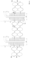
- the exchanger 107 comprises tubes 1, preferably called a tube bundle, and plates 50.
- the tubes are configured to receive the heat transfer fluid 103.
- the plates 50 comprise openings 52 for tubes 1 through which the tubes 1 are arranged.
- the heat transfer fluid is typically water, or steam, or any other fluid with heat transfer properties can be used, for example a thermal oil such as polychlorinated biphenyl (therminol ® ) or a mixture of isomers of (di)benzyltoluene (Jarytherm ® ).
- a thermal oil such as polychlorinated biphenyl (therminol ® ) or a mixture of isomers of (di)benzyltoluene (Jarytherm ® ).
- the tubes 1 are connected to a fluid circuit of heat transfer fluid.
- a first end of the tubes 1 constitutes the inlet of the heat transfer fluid while the other end constitutes the outlet of the heat transfer fluid.
- the direction of circulation of the fluid is not unique, the fluid can, depending on whether it is charging or discharging, circulate in one direction or in the other.
- the case considered is a load.
- the description is made for heat storage at positive temperature, it should be noted that it is also valid for cold storage with a PCM which can then be water.
- the mechanical constraints are stronger during the solidification of water, due to its higher density in the liquid state than in the solid state, unlike the majority of PCMs used for latent heat storage at positive temperatures.
- the hydraulic connection of the tubes 1 can be made via manifolds, a tube plate, a water box, a conical divergent, etc.
- a tube plate In Figure 1 an upper collector 101 and a lower collector 102 are shown.
- the system may comprise a plurality of exchangers arranged in an enclosure 107.
- the exchanger brings heat into the enclosure, there is a heat exchange from the heat transfer fluid to the MCP through the exchanger. This heat will allow the transformation of the MCP from the first phase to the second phase which will then store the heat from the heat transfer fluid.
- the exchanger cools the MCP, there is a heat exchange from the MCP to the heat transfer fluid through the exchanger, which allows the transition from the second phase to the first phase. This transformation is exothermic. The heat released is recovered by the heat transfer fluid.
- the tubes 1 of the exchanger are advantageously arranged in a bundle of tubes.
- the tubes 1 are arranged parallel to each other.
- the tubes are arranged vertically and preferably, the enclosure 107 extends in a main vertical direction.
- Each tube 1 extends along a longitudinal axis 3.
- Each tube 1 comprises on its surface 11, corresponding to the external surface of the tube, a helical fin 2.
- the helical fin 2 is a fin which is wound helically on the surface 11 of the tube 1 along the longitudinal axis of the tube 1.
- each tube 1 comprises a helical fin 2.
- each tube 1 comprises several helical fins arranged in continuity or discontinuity.
- the helical shape of the fin 2 helps to facilitate the convection movements of the MCP 105 in the enclosure 107 and in particular around the tubes 1. More precisely, the helical fin facilitates the formation on its surface of a continuous channel of liquid MCP. allowing it to rise and expand freely on the free surface, thus limiting the risk of exerting significant mechanical stress on the exchanger during the volumetric expansion of the MCP. In addition, the helical shape of the radial fin facilitates the manufacture of finned tubes.
- the helical fin 2 can be either extruded, or crimped in a groove, or welded, at high frequency or laser for example, to the outer surface 11 of the tube 1 following a helicoid.
- the tubes 1 are advantageously cylindrical.
- the tubes 1 have a diameter 6 generally between 17.2mm (DN10) and 60.3mm (DN50), the most common diameter being 33.7mm (DN25).
- the helical fins 2 have a maximum external diameter 7 of 56mm.
- the maximum external diameter 7 of the helical fin 2 corresponds to the sum of the diameter of the tube 6 and the height of the fin 12 of the helical fin 2.
- the tube 1 comprises at least one insertion end 4 through which the tube 1 is introduced into the openings 52 of the plates 50.
- the tube 1 comprises a portion 5 arranged at the insertion end 4 which is devoid of a fin. This portion is called the insertion end portion 5.
- the insertion end portion 5 is for example smooth.
- the insertion end portion 5 comprises only the tube 1 and its surface 11.
- the surface 11 of the tube 1 may be smooth or for example grooved to facilitate the attachment of the fins without being limiting.
- This insertion end portion 5 makes it easier to introduce the tube 1 into the openings 52 of the plate 50.
- the tube 1 comprises an end portion opposite the insertion end which is also devoid of a fin.
- This arrangement advantageously makes it easier to adapt the size of the tubes 1 to the dimensions of the enclosure 107 by allowing easier cutting of the tubes 1.
- the absence of fins at the ends of the tubes also allows them to be assembled to the tube collector plates or to the hydraulic collection or distribution manifolds.
- the helical fin 2 has a maximum external diameter 7 constant over the entire tube 1.
- the helical fin 2 has a diameter 7 advantageously decreasing in the direction of the end of the fin arranged opposite the insertion end 4 of the tube.
- the tube 1 comprises a decreasing portion 8 in which the maximum external diameter 7 of the helical fin 2 decreases in the direction of the insertion end 4 of the tube.
- the maximum external diameter 7 of the helical fin 2 decreases as it approaches this insertion end 4 of the tube 1.
- a tube 1 has a length before connection to the upper collector 100 and lower collector 102 of between 1m and 6m, possibly the insertion portion 5 represents from 15 mm to 50 mm, possibly the decrease portion represents from 20 mm to 50 mm.
- the helical fin 2 is advantageously defined by its pitch 9, its height 12, advantageously the thickness of the helical fin 2 at its base 14 and the thickness of the helical fin 2 at its apex 15, the thickness 17 of the helical fin at its insertion radius and possibly the length 13 of the helical fin 2 and possibly the height 16 separating two successive bases 14 of the helical fin 2 along a vertical axis, more precisely separating the upper base face from the lower face of the next base.
- the pitch 9 of the helical fin 2 is chosen as a function of the plates 50 and in particular the reliefs 51 described below.
- the pitch 9 is understood as the distance between 2 successive apexes of the helical fin 2 along a vertical axis.
- the height 12 of the fin is understood as the distance between the top 15 and the base 16 of the helical fin 2, corresponding to the surface 11 of the tube 1.
- pitch 9 is defined to have a number of fins/meter between 196 fins/meter and 473 fins/meter, i.e. pitch 9 is between 20mm and 55mm, more precisely between 21mm and 51mm.
- the pitch 9 of the helical fin 2 is chosen so that the helical fin 2 is in contact with the plates 50 and advantageously ensures a plane contact 10 between a surface of the plate 50 and a surface of the helical fin 2.
- This plane contact 10 between the plate 50 and the helical fin 2 is optimized to allow thermal conduction between the heat transfer fluid 103 and the MCP 105 passing through the plates 50, the helical fin 2 and the tube 1.
- this plane contact 10 is made on at least a part of the height 12 of the fin corresponding to half the difference between the maximum external diameter 7 of the helical fin and the diameter 57 of the opening 52.
- This plane contact 10 advantageously has at least 25% of the height 12 of the fin helical, preferably at least 50%.
- the helical fin 2 can either have a decreasing thickness from its base 14 to its apex 15, or have a constant thickness from its base 14 to its apex 15.
- the fin helical 2 and the plates 50 are configured so that the helical fin 2 comes into contact with the plate 50 alternately by the first face 54 and the second face 55 of the plate 50.
- This arrangement is notably made possible by the screwing of the tube 1 onto the plate 50.
- the tube 1 is in continuous contact with the plate 50 via the helical fin 2. It is not possible to have a clearance between the helical fin 2 and the plate 50 unlike what happens with the inserts on the tubes of the state of the art.
- the tube 1 comprises at its insertion end 4 an imprint, not shown in the figures, configured to cooperate with a driving tool for screwing the tube 1 into the openings 52 of the plates 50.
- an imprint for example, a grooved, hexagonal, or other imprint may be provided at the insertion end 4.
- this imprint is removed to allow adjustment of the tube 1 to the dimensions of the enclosure 107 and to facilitate assembly of the tube 1 at its ends to the upper collector 101 and to the lower collector 102.
- all of the tubes 1 of a tube bundle of the SST 100 are identical. However, it may be provided that tubes 1 of the tube bundle are different in structure, dimensions, shape, etc.
- the SST 100 comprises plates 52 advantageously forming part of the exchanger in the sense that they participate in the heat exchange between the MCP 105 and the heat transfer fluid 103.
- the plates 50 are preferably arranged perpendicular to the tubes 1.
- the tubes 1 are parallel to each other and the plates 50 are parallel to each other.
- the plates 50 comprise openings 52 for tubes 1.
- the openings 52 are produced with material removal, preferably by pre-cutting and then stamping.
- the openings 52 are configured to receive the tubes 1.
- Each opening 52 receives a tube 1.
- the opening 52 is of a shape complementary to that of the tube 1 and advantageously to that of the helical fin.
- the opening 52 has a diameter 57 less than the maximum diameter 7 of the helical fin 2.
- the diameter 57 of the opening is greater than or equal to the diameter 6 of the tube 1.
- the tube 1 can be introduced into the opening 52 and the helical fin 2 is in contact with the opening 52 to advantageously allow insertion by screwing and preferably in contact between the helical fin 2 and the plate 50.
- each opening 52 comprises at least one slot 61 configured to allow the helical fin 2 of the tube 1 to pass into the opening of the plate 52 when it was inserted.
- the slot 61 advantageously extends from the periphery of the opening 52.
- the slot 61 extends along a main component parallel to the radius of the opening 52.
- the slot 61 may be inclined relative to the radius of the opening 52.
- the slot 61 is defined in particular by its depth 62 corresponding to the distance separating the base of the slot 61 at the periphery of the opening 52 and the top of the slot, opposite its base.
- the depth 62 of the slot 61 is advantageously configured to allow the helical fin 2 to pass and more precisely the depth 62 is at least equal to half the difference between the maximum external diameter 7 of the helical fin 2 and the diameter 57 of the opening 52. This arrangement makes it possible to have the longitudinal axis 3 of the tube 1 centered in the opening 52.
- the slot 61 may be rectangular or triangular in shape as illustrated in the Figure 2B .
- the slot 61 is advantageously of a shape complementary to that of the helical fin 2. If the helical fin has a constant thickness from its base 14 to its apex 15, the slot 61 will preferably be of rectangular shape, while if the helical fin 2 has a decreasing thickness from its base 14 to its apex 15, the slot 61 will preferably be of triangular shape.
- the slot 61 advantageously has a width at least equal to the thickness 17 of the helical fin at its insertion radius.
- the insertion radius of the helical fin 2 corresponds, preferably to half the diameter 57 of the opening 52. This arrangement makes it easier to insert the tube 1 and the fin 2 into the opening 52 without offsetting the tube 1.
- the edges of the slot 61 can be offset, that is to say arranged at least partly on a different longitudinal plane of the plate.
- the two edges of the slot 61 can be offset in height so as to facilitate the insertion of the helical fin.
- the plate 50 has a thickness 60.
- the thickness 60 of the plate preferably at the level of the opening 52, is in line with the pitch 9 of the helical fin 2 and more preferably with the height 16 separating two successive bases 14 of the helical fin 2.
- the plates 50 have a shape corresponding to the shape of the interior of the enclosure 107.
- the plates 50 are configured to be advantageously stacked in the enclosure 107 of the SST 100.
- the plates 50 are circular or hexagonal in shape.
- the plates 50 advantageously form a cassette of plates, i.e. a set of plates.
- Each plate 50 extends along a plate plane 56 in a direction longitudinal, advantageously perpendicular to the longitudinal axis 3 of the tubes 1.
- the plates 50 or at least some plates, for example one plate out of two alternating, comprise reliefs 51.
- the reliefs 51 are formed by plastic deformation of the plates 50 forming so-called stamped plates 50.
- the reliefs 51 are configured to act as spacers for plates 50.
- the plates 50 are stacked in contact with each other, preferably at least partially by their reliefs 51.
- a relief 51 may be in contact with another opposite relief 51 formed on a plate above or below it or in contact with the plate 50 itself.
- the reliefs 51 allow the plates 50 to be superimposed in contact with each other.
- the plates 50 are stacked and rest on each other by contact zones 58. According to the invention, it is not necessary to ensure the superposition of the plates 2 to provide means for fixing the plates 2 to the tubes 1.
- the reliefs 51 have a function of spacers for the plates 2.
- the reliefs make it possible to maintain a space between two juxtaposed plates 2. Indeed, the plates 2 are spaced from each other by at least the height of the reliefs 51 of a plate 50, or even the sum of the height of the reliefs of 2 successive plates 50 illustrating the spacing 59 between the plates.
- the plates 50 comprise a first face 54 and a second opposite face 55.
- the reliefs 51 are preferably formed on at least one of the two faces 54-55 of the plates. It is thus understood that the reliefs protrude on at least one of the two faces 54-55. According to one possibility illustrated in figures 3 And 4 , the reliefs 51 protrude on the two faces 54 and 55. According to a possibility illustrated in particular in the figure, the plates 50 comprise reliefs 51 and advantageously flat portions spacing the reliefs.
- the reliefs 51 can take very varied forms such as point projections or longitudinal reliefs extending from one edge to the other of a plate 2, for example ribs, or undulations as illustrated in figures 3 And 4 .
- the reliefs 51 may form a network following a recurring pattern alternating for example a relief 51 oriented towards the first face 54 of the plate 50, called the upper relief, and a relief 51 oriented towards the second face 55 of the plate 50, called the lower relief.
- the ribs extend from one side to the other of the plate 2.
- the reliefs 51 extend in a main direction perpendicular to the plate plane 56 from which they extend.
- the reliefs 51 may be ribs of parallelepiped shape or of rounded shape.
- the reliefs 51 are configured to generate a contact zone 59 between two juxtaposed plates 50a and 50b.
- the contact zone 59 is advantageously a planar contact zone.
- the stacking of the plates 50 allows some of their reliefs 51 to come into contact, for example the lower reliefs of a plate 50a on top are in contact with the upper reliefs of the plate 50b located below.
- the reliefs 51 are formed by stamping the plate 50, they can also be obtained by other types of mechanical machining (modeling, stamping, Guérin process, or engraving for the smallest reliefs) or laser.
- the reliefs 51 are formed by deformation of the plate 50 and not by adding material to the plate 50.
- the reliefs 51 and the plate 50 are integral.
- the reliefs 51 and the face 54 or 55 of the plate 50 form a monolithic part in order to optimize heat transfers.
- the shape of the reliefs must be chosen to ensure a mechanical function and a thermal function.
- Mechanical because the reliefs allow the plates 50 to rest on each other, thus ensuring their spacing 59 and advantageously maintaining the overall structure.
- the reliefs 51 and therefore the spacing 59 generated by them must be compatible with the pitch 9 of the helical fin 2 of the tube 1.
- the plates 50 and the tubes 1 are in physical and thermal contact.
- the weight of the plates 50 thus rests both on the helical fins 2 and on themselves thanks to the reliefs 51.
- Thermal because the reliefs 51 increase the exchange surface and improve the heat transfers in the direction orthogonal to the plates 50: indeed, the plates 50 being in contact with each other in the vertical direction, advantageously by the contact zones 59, they promote conductive heat transfers in this direction.
- the plates 50 advantageously extend over the entire transverse surface of the enclosure 107, consequently there are no dead zones, that is to say zones distant from the plates 50, as may exist with finned tubes of the state of the art or with inserts of the state of the art.
- the set of 50 plates forms a 3-dimensional structured plate cassette also called a matrix plate cassette.
- the 51 reliefs have a minimum thickness of 8mm and a maximum of 10cm, more preferably between 2 and 5cm.
- the thickness of the reliefs must be readjusted according to the number of tubes per square meter and the desired power.
- the 50 plates of different geometries can be stacked in the same exchanger.
- the 50 plates can be stacked on top of each other of different ways for example with the ribs of a plate 50 parallel to the ribs of the plates 50 stacked on either side or with ribs of a plate 50 perpendicular to the ribs of the other plates 50 stacked on either side.
- the stack comprises plates 50 having a relief and flat plates without relief.
- the plates 50 having reliefs 51 have reliefs 51 extending from the two faces 54, 55 of the plate 50.
- the stack successively comprises a plate 50 with relief, then a flat plate then a plate 50 with relief...
- the plates 50 are stacked by gravity.
- the plates 50 are perforated and preferably without removal of material.
- the plates 50 include perforations.
- the plates 50 are advantageously perforated without removing material as illustrated in Figures 2A And 2B .
- the reliefs 51 are openwork.
- the days are formed in the plate 50 mechanically by punching or shearing operations.
- the 50 plates are preferably embossed, cut, or even made of expanded metal.
- the plates 50 are secured to the tubes 1 and/or to the helical fins 2, for example by stirring.
- the invention also relates to a method for assembling the SST 100 described above.
- the method comprises a step of stacking the plates 50 on top of each other, advantageously in contact while maintaining a space between two juxtaposed plates 50 thanks to the reliefs 51.
- the plates 50 are stacked so that the openings 52 for tubes 1 are aligned.
- the alignment of the openings 52 can be achieved using assembly guides, which are preferably metal bars of the same diameter as the tubes 1.
- the stacking is advantageously done by gravity.
- the plates 50 rest on top of each other.
- the tubes 1 are then introduced in the openings 52 of the plates 50.
- the tubes 1 are introduced into the openings 52 of the plates 50 by screwing the helical fin 2 onto the opening 52.
- the method then comprises connecting the ends of the tubes 1 to the heat transfer fluid network 103.
- the ends of the tubes 1 are connected respectively to the upper collector 101 and lower collector 102.
- the tubes 1 are brought to the dimensions of the enclosure and/or the imprint is removed and/or the insertion end portion 5 is removed.
- the method then comprises the installation in the enclosure 107 of the heat exchanger formed of the tubes 1 with helical fins 2 and the plates 50 forming the plate cassette.
Landscapes
- Engineering & Computer Science (AREA)
- Physics & Mathematics (AREA)
- Thermal Sciences (AREA)
- Mechanical Engineering (AREA)
- General Engineering & Computer Science (AREA)
- Geometry (AREA)
- Heat-Exchange Devices With Radiators And Conduit Assemblies (AREA)
Applications Claiming Priority (1)
| Application Number | Priority Date | Filing Date | Title |
|---|---|---|---|
| FR2311574A FR3154794B1 (fr) | 2023-10-25 | 2023-10-25 | Système de stockage thermique à MCP optimisé et son procédé d’assemblage |
Publications (3)
| Publication Number | Publication Date |
|---|---|
| EP4545896A1 true EP4545896A1 (de) | 2025-04-30 |
| EP4545896C0 EP4545896C0 (de) | 2026-02-04 |
| EP4545896B1 EP4545896B1 (de) | 2026-02-04 |
Family
ID=89308588
Family Applications (1)
| Application Number | Title | Priority Date | Filing Date |
|---|---|---|---|
| EP24208401.0A Active EP4545896B1 (de) | 2023-10-25 | 2024-10-23 | Optimiertes wärmespeichersystem und dessen herstellungsverfahren |
Country Status (2)
| Country | Link |
|---|---|
| EP (1) | EP4545896B1 (de) |
| FR (1) | FR3154794B1 (de) |
Citations (3)
| Publication number | Priority date | Publication date | Assignee | Title |
|---|---|---|---|---|
| EP3175196A1 (de) * | 2014-07-31 | 2017-06-07 | Commissariat à l'Énergie Atomique et aux Énergies Alternatives | Vorrichtung zur speicherung von energie mittels eines speicherstoffes und zugehöriges speicherverfahren |
| EP3214398A1 (de) * | 2016-03-04 | 2017-09-06 | Commissariat à l'Energie Atomique et aux Energies Alternatives | Einrichtung zur energiespeicherung mit phasenwechselmaterial einschliesslich elektrische ladung integriert in dem flüssigkeitskreislauf |
| EP3274642A1 (de) * | 2015-03-27 | 2018-01-31 | Commissariat à l'Énergie Atomique et aux Énergies Alternatives | Vorrichtung zur speicherung von wärmeenergie mit einem wärmeübertragungsfluid- und pcm-wärmetauscher sowie montageverfahren dafür |
-
2023
- 2023-10-25 FR FR2311574A patent/FR3154794B1/fr active Active
-
2024
- 2024-10-23 EP EP24208401.0A patent/EP4545896B1/de active Active
Patent Citations (3)
| Publication number | Priority date | Publication date | Assignee | Title |
|---|---|---|---|---|
| EP3175196A1 (de) * | 2014-07-31 | 2017-06-07 | Commissariat à l'Énergie Atomique et aux Énergies Alternatives | Vorrichtung zur speicherung von energie mittels eines speicherstoffes und zugehöriges speicherverfahren |
| EP3274642A1 (de) * | 2015-03-27 | 2018-01-31 | Commissariat à l'Énergie Atomique et aux Énergies Alternatives | Vorrichtung zur speicherung von wärmeenergie mit einem wärmeübertragungsfluid- und pcm-wärmetauscher sowie montageverfahren dafür |
| EP3214398A1 (de) * | 2016-03-04 | 2017-09-06 | Commissariat à l'Energie Atomique et aux Energies Alternatives | Einrichtung zur energiespeicherung mit phasenwechselmaterial einschliesslich elektrische ladung integriert in dem flüssigkeitskreislauf |
Non-Patent Citations (1)
| Title |
|---|
| ZONOUZI SAJJAD AHANGAR ET AL: "Numerical investigation of using helical fins for the enhancement of the charging process of a latent heat thermal energy storage system", JOURNAL OF ENERGY STORAGE, ELSEVIER BV, NL, vol. 49, 11 February 2022 (2022-02-11), XP087029797, ISSN: 2352-152X, [retrieved on 20220211], DOI: 10.1016/J.EST.2022.104157 * |
Also Published As
| Publication number | Publication date |
|---|---|
| FR3154794B1 (fr) | 2025-10-24 |
| EP4545896C0 (de) | 2026-02-04 |
| FR3154794A1 (fr) | 2025-05-02 |
| EP4545896B1 (de) | 2026-02-04 |
Similar Documents
| Publication | Publication Date | Title |
|---|---|---|
| EP2904343B1 (de) | Wärmetauscher für thermisches speichersystem | |
| EP3175196B1 (de) | Vorrichtung zur speicherung von energie mittels eines speicherstoffes und zugehöriges speicherverfahren | |
| EP2906895B1 (de) | Herstellungsverfahren für einen wärmetauscher mit phasenwechselmaterial, entsprechenden wärmetauscher und seine hochtemperaturverwendung | |
| EP3274642B1 (de) | Vorrichtung zur speicherung von wärmeenergie mit einem wärmeübertragungsfluid- und pcm-wärmetauscher sowie montageverfahren dafür | |
| EP4212814B1 (de) | Modulare wärmespeicheranordnung mit phasenwechselmaterial, dessen herstellung vereinfachten herstellung | |
| EP3494352A1 (de) | Plattenwärmetauschermodul, bei dem die kanäle als eingang einer zone mit gleichmässiger strömungsverteilung und einer flüssigkeitsverzweigungszone integriert sind | |
| EP4086556A1 (de) | Plattenwärmetauschermodul mit kanälen, das mindestens einen durch noppen gebildeten bereich für die zufuhr und verteilung von fluiden umfasst | |
| EP4019878A1 (de) | Thermisches speichermodul aus phasenwechselmaterial, dessen herstellung vereinfacht ist | |
| WO2003071626A2 (fr) | Structure alvéolaire et procédé de fabrication d'une telle structure. | |
| EP4639062A1 (de) | Plattenwärmetauschermodul mit plattenkanälen die durch stifte und verdickte kanten begrenzten fluidumzufuhr- und verteilungszone enthalten | |
| EP3405736B1 (de) | Wärmetransfer-fluidwärmetauscher mit optimierter anordnung und wärmespeichervorrichtung mit einem speicherstoff und mit solch einem tauscher | |
| FR3038376B1 (fr) | Dispositif de stockage d'energie par materiau a changement de phase et son procede de stockage | |
| EP4545896B1 (de) | Optimiertes wärmespeichersystem und dessen herstellungsverfahren | |
| CA2509777A1 (fr) | Echangeur thermique procedes et moyens de fabrication de cet echangeur | |
| EP2411117B1 (de) | Vorrichtung zum reinigen eines mit partikeln beladenen fluids durch thermophoretische kräfte | |
| EP3214398B1 (de) | Einrichtung zur energiespeicherung mit phasenwechselmaterial einschliesslich elektrische ladung integriert in dem flüssigkeitskreislauf | |
| EP3553443B1 (de) | Vereinfachte wärmeröhre und pulsierte wärmeröhre | |
| FR3050263A1 (fr) | Dispositif de stockage d'energie thermique par materiau a changement de phase comprenant un element permettant de creer une perte de charge | |
| EP4679024A1 (de) | Thermisches speichersystem unter verwendung eines phasenwechselmaterials | |
| WO2010100367A1 (fr) | Appareil de séparation d'air incorporant un échangeur de chaleur à plaques | |
| EP4696971A1 (de) | Vorrichtung zum austausch und speichern von wärmeenergie | |
| WO2025163105A1 (fr) | Module d'échangeur de chaleur à deux circuits de circulation de fluide à contre-courant, comprenant une structure d'échange thermique de surface minimale triplement périodique (tpms) à motifs élémentaires schwartz d à orientation privilégiée dans la calandre du module | |
| FR3051244A1 (fr) | Echangeur de chaleur a plaques, procede de fabrication et utilisation correspondante | |
| FR3059570A1 (fr) | Procede de fabrication d'un garnissage structure par une methode de fabrication additive | |
| WO2025181225A1 (en) | Plate stack |
Legal Events
| Date | Code | Title | Description |
|---|---|---|---|
| PUAI | Public reference made under article 153(3) epc to a published international application that has entered the european phase |
Free format text: ORIGINAL CODE: 0009012 |
|
| STAA | Information on the status of an ep patent application or granted ep patent |
Free format text: STATUS: REQUEST FOR EXAMINATION WAS MADE |
|
| 17P | Request for examination filed |
Effective date: 20241023 |
|
| AK | Designated contracting states |
Kind code of ref document: A1 Designated state(s): AL AT BE BG CH CY CZ DE DK EE ES FI FR GB GR HR HU IE IS IT LI LT LU LV MC ME MK MT NL NO PL PT RO RS SE SI SK SM TR |
|
| GRAP | Despatch of communication of intention to grant a patent |
Free format text: ORIGINAL CODE: EPIDOSNIGR1 |
|
| STAA | Information on the status of an ep patent application or granted ep patent |
Free format text: STATUS: GRANT OF PATENT IS INTENDED |
|
| INTG | Intention to grant announced |
Effective date: 20250829 |
|
| GRAS | Grant fee paid |
Free format text: ORIGINAL CODE: EPIDOSNIGR3 |
|
| GRAA | (expected) grant |
Free format text: ORIGINAL CODE: 0009210 |
|
| STAA | Information on the status of an ep patent application or granted ep patent |
Free format text: STATUS: THE PATENT HAS BEEN GRANTED |
|
| AK | Designated contracting states |
Kind code of ref document: B1 Designated state(s): AL AT BE BG CH CY CZ DE DK EE ES FI FR GB GR HR HU IE IS IT LI LT LU LV MC ME MK MT NL NO PL PT RO RS SE SI SK SM TR |
|
| REG | Reference to a national code |
Ref country code: CH Ref legal event code: F10 Free format text: ST27 STATUS EVENT CODE: U-0-0-F10-F00 (AS PROVIDED BY THE NATIONAL OFFICE) Effective date: 20260204 Ref country code: GB Ref legal event code: FG4D Free format text: NOT ENGLISH |
|
| REG | Reference to a national code |
Ref country code: DE Ref legal event code: R096 Ref document number: 602024002409 Country of ref document: DE |
|
| REG | Reference to a national code |
Ref country code: IE Ref legal event code: FG4D Free format text: LANGUAGE OF EP DOCUMENT: FRENCH |
|
| U01 | Request for unitary effect filed |
Effective date: 20260210 |
|
| U07 | Unitary effect registered |
Designated state(s): AT BE BG DE DK EE FI FR IT LT LU LV MT NL PT RO SE SI Effective date: 20260216 |
|
| PG25 | Lapsed in a contracting state [announced via postgrant information from national office to epo] |
Ref country code: RS Free format text: LAPSE BECAUSE OF FAILURE TO SUBMIT A TRANSLATION OF THE DESCRIPTION OR TO PAY THE FEE WITHIN THE PRESCRIBED TIME-LIMIT Effective date: 20260504 |
|
| PG25 | Lapsed in a contracting state [announced via postgrant information from national office to epo] |
Ref country code: ES Free format text: LAPSE BECAUSE OF FAILURE TO SUBMIT A TRANSLATION OF THE DESCRIPTION OR TO PAY THE FEE WITHIN THE PRESCRIBED TIME-LIMIT Effective date: 20260204 |
|
| PG25 | Lapsed in a contracting state [announced via postgrant information from national office to epo] |
Ref country code: PL Free format text: LAPSE BECAUSE OF FAILURE TO SUBMIT A TRANSLATION OF THE DESCRIPTION OR TO PAY THE FEE WITHIN THE PRESCRIBED TIME-LIMIT Effective date: 20260204 |
|
| PG25 | Lapsed in a contracting state [announced via postgrant information from national office to epo] |
Ref country code: GR Free format text: LAPSE BECAUSE OF FAILURE TO SUBMIT A TRANSLATION OF THE DESCRIPTION OR TO PAY THE FEE WITHIN THE PRESCRIBED TIME-LIMIT Effective date: 20260505 |
|
| PG25 | Lapsed in a contracting state [announced via postgrant information from national office to epo] |
Ref country code: NO Free format text: LAPSE BECAUSE OF FAILURE TO SUBMIT A TRANSLATION OF THE DESCRIPTION OR TO PAY THE FEE WITHIN THE PRESCRIBED TIME-LIMIT Effective date: 20260504 |
|
| PG25 | Lapsed in a contracting state [announced via postgrant information from national office to epo] |
Ref country code: HR Free format text: LAPSE BECAUSE OF FAILURE TO SUBMIT A TRANSLATION OF THE DESCRIPTION OR TO PAY THE FEE WITHIN THE PRESCRIBED TIME-LIMIT Effective date: 20260204 |
|
| PG25 | Lapsed in a contracting state [announced via postgrant information from national office to epo] |
Ref country code: IS Free format text: LAPSE BECAUSE OF FAILURE TO SUBMIT A TRANSLATION OF THE DESCRIPTION OR TO PAY THE FEE WITHIN THE PRESCRIBED TIME-LIMIT Effective date: 20260604 |