EP4545910A1 - Positionssensor und kalibrierung - Google Patents
Positionssensor und kalibrierung Download PDFInfo
- Publication number
- EP4545910A1 EP4545910A1 EP23206454.3A EP23206454A EP4545910A1 EP 4545910 A1 EP4545910 A1 EP 4545910A1 EP 23206454 A EP23206454 A EP 23206454A EP 4545910 A1 EP4545910 A1 EP 4545910A1
- Authority
- EP
- European Patent Office
- Prior art keywords
- track
- magnetic
- positions
- calibration
- previous
- Prior art date
- Legal status (The legal status is an assumption and is not a legal conclusion. Google has not performed a legal analysis and makes no representation as to the accuracy of the status listed.)
- Pending
Links
Images



Classifications
-
- G—PHYSICS
- G01—MEASURING; TESTING
- G01D—MEASURING NOT SPECIALLY ADAPTED FOR A SPECIFIC VARIABLE; ARRANGEMENTS FOR MEASURING TWO OR MORE VARIABLES NOT COVERED IN A SINGLE OTHER SUBCLASS; TARIFF METERING APPARATUS; MEASURING OR TESTING NOT OTHERWISE PROVIDED FOR
- G01D18/00—Testing or calibrating apparatus or arrangements provided for in groups G01D1/00 - G01D15/00
- G01D18/001—Calibrating encoders
-
- G—PHYSICS
- G01—MEASURING; TESTING
- G01D—MEASURING NOT SPECIALLY ADAPTED FOR A SPECIFIC VARIABLE; ARRANGEMENTS FOR MEASURING TWO OR MORE VARIABLES NOT COVERED IN A SINGLE OTHER SUBCLASS; TARIFF METERING APPARATUS; MEASURING OR TESTING NOT OTHERWISE PROVIDED FOR
- G01D5/00—Mechanical means for transferring the output of a sensing member; Means for converting the output of a sensing member to another variable where the form or nature of the sensing member does not constrain the means for converting; Transducers not specially adapted for a specific variable
- G01D5/12—Mechanical means for transferring the output of a sensing member; Means for converting the output of a sensing member to another variable where the form or nature of the sensing member does not constrain the means for converting; Transducers not specially adapted for a specific variable using electric or magnetic means
- G01D5/14—Mechanical means for transferring the output of a sensing member; Means for converting the output of a sensing member to another variable where the form or nature of the sensing member does not constrain the means for converting; Transducers not specially adapted for a specific variable using electric or magnetic means influencing the magnitude of a current or voltage
- G01D5/142—Mechanical means for transferring the output of a sensing member; Means for converting the output of a sensing member to another variable where the form or nature of the sensing member does not constrain the means for converting; Transducers not specially adapted for a specific variable using electric or magnetic means influencing the magnitude of a current or voltage using Hall-effect devices
- G01D5/145—Mechanical means for transferring the output of a sensing member; Means for converting the output of a sensing member to another variable where the form or nature of the sensing member does not constrain the means for converting; Transducers not specially adapted for a specific variable using electric or magnetic means influencing the magnitude of a current or voltage using Hall-effect devices influenced by the relative movement between the Hall device and magnetic fields
-
- G—PHYSICS
- G01—MEASURING; TESTING
- G01D—MEASURING NOT SPECIALLY ADAPTED FOR A SPECIFIC VARIABLE; ARRANGEMENTS FOR MEASURING TWO OR MORE VARIABLES NOT COVERED IN A SINGLE OTHER SUBCLASS; TARIFF METERING APPARATUS; MEASURING OR TESTING NOT OTHERWISE PROVIDED FOR
- G01D5/00—Mechanical means for transferring the output of a sensing member; Means for converting the output of a sensing member to another variable where the form or nature of the sensing member does not constrain the means for converting; Transducers not specially adapted for a specific variable
- G01D5/12—Mechanical means for transferring the output of a sensing member; Means for converting the output of a sensing member to another variable where the form or nature of the sensing member does not constrain the means for converting; Transducers not specially adapted for a specific variable using electric or magnetic means
- G01D5/244—Mechanical means for transferring the output of a sensing member; Means for converting the output of a sensing member to another variable where the form or nature of the sensing member does not constrain the means for converting; Transducers not specially adapted for a specific variable using electric or magnetic means influencing characteristics of pulses or pulse trains; generating pulses or pulse trains
- G01D5/24471—Error correction
- G01D5/2449—Error correction using hard-stored calibration data
-
- G—PHYSICS
- G01—MEASURING; TESTING
- G01D—MEASURING NOT SPECIALLY ADAPTED FOR A SPECIFIC VARIABLE; ARRANGEMENTS FOR MEASURING TWO OR MORE VARIABLES NOT COVERED IN A SINGLE OTHER SUBCLASS; TARIFF METERING APPARATUS; MEASURING OR TESTING NOT OTHERWISE PROVIDED FOR
- G01D5/00—Mechanical means for transferring the output of a sensing member; Means for converting the output of a sensing member to another variable where the form or nature of the sensing member does not constrain the means for converting; Transducers not specially adapted for a specific variable
- G01D5/12—Mechanical means for transferring the output of a sensing member; Means for converting the output of a sensing member to another variable where the form or nature of the sensing member does not constrain the means for converting; Transducers not specially adapted for a specific variable using electric or magnetic means
- G01D5/244—Mechanical means for transferring the output of a sensing member; Means for converting the output of a sensing member to another variable where the form or nature of the sensing member does not constrain the means for converting; Transducers not specially adapted for a specific variable using electric or magnetic means influencing characteristics of pulses or pulse trains; generating pulses or pulse trains
- G01D5/245—Mechanical means for transferring the output of a sensing member; Means for converting the output of a sensing member to another variable where the form or nature of the sensing member does not constrain the means for converting; Transducers not specially adapted for a specific variable using electric or magnetic means influencing characteristics of pulses or pulse trains; generating pulses or pulse trains using a variable number of pulses in a train
- G01D5/2451—Incremental encoders
- G01D5/2452—Incremental encoders incorporating two or more tracks having an (n, n+1, ...) relationship
Definitions
- the invention relates to the field of position sensor. More specifically it relates to magnetic sensing systems and signal processing for position sensing.
- Position sensing systems are usually included in devices where it is necessary to detect the position of some of their components.
- many engines include angular position sensing systems to detect the relative position of the rotor relative to the stator, in order to ensure proper powering of the engine coils.
- Contactless position sensors usually include a magnetic sensor and a moveable magnetic structure including multipolar magnets which improve resolution and accuracy of the relative positioning. Since the structures are divided into sectors, it is not possible to identify the position of the angle sector itself with just a magnetic sensor, so information relative to absolute angular position is lost.
- magnetic structures include two multipole magnetic tracks with different number of poles, so the full 360° range can be reconstructed by combining the signals of both tracks obtained by a pair of sensors.
- a combination between the signals from the two tracks is used to discriminate the sector, while the signal of the master track is used to measure the angle.
- these types of systems suffer from cross talk between the fields, so there are inaccuracies in the detected position.
- the present invention provides a method of calibrating a magnetic sensor system for a position sensor.
- the method comprises providing a movable magnetic structure including a master track and a nonius track, each track comprising multipoles.
- the number of multipoles of the master track is different from the number of multipoles of the nonius track.
- the position of the magnetic structure is changed over a calibration range while measuring at least four components of the magnetic field generated by the magnetic structure, and respective (at least four) measurement signals are provided.
- the method further comprises determining a plurality of uncorrected positions of the magnetic structure over the calibration range, based on ratios of the measurement signals.
- a plurality of reference positions is provided.
- the reference position can be provided so that they correspond to the measurements of the at least four components of the magnetic field.
- the plurality of uncorrected positions are combined with at least one periodic correction function, the periodic correction function being a function of the uncorrected positions and having two function coefficients adapted to minimize a position error over the calibration range between the reference positions and the uncorrected positions of the magnetic structure; the error may include for example error induced by the cross talk between the two tracks.
- the method further comprises obtaining the plurality of reference positions using a reference encoder. It is an advantage that the encoder may have high accuracy and may be used only during calibration.
- obtaining the position of the magnetic structure further comprises performing amplitude and phase matching of the measurement signals.
- obtaining the calibration coefficient comprises obtaining the calibration coefficient uncorrected positions and at most two periodic correction functions.
- the method further comprises defining a harmonic of the at least one periodic function, being equal to the difference between the number of multipoles of the master track and the number of multipoles of the nonius track.
- the method further comprises defining a harmonic of the at least one periodic function beomg equal to the sum of the number of multipoles of the master track and the number of multipoles of the nonius track. It is an advantage that the contribution of harmonics in the error curve due to the cross talk can be reduced.
- measuring at least four components comprises measuring at least two pairs of orthogonal components, e.g. at two locations.
- Hall sensors can be used to implement such measurements, allowing simultaneous measurements of two orthogonal components.
- the method further comprises further comprising determining a plurality of corrected positions based on the correction function and linearizing the corrected positions to match the reference positions. It is an advantage that non-linearity due to the imperfections of the magnet can be compensated.
- linearizing the corrected positions comprises providing a corrective value by interpolation of points stored in a look-up table.
- the present invention provides a method of sensing the position of a magnetic structure comprising providing the calibration coefficient by following the method of any one of the previous claims, determining the position of the magnetic structure , and applying the calibration function being the periodic function with the calibration coefficients calculated during calibration. For example, the same periodic function can be applied.
- measuring the position further comprises using a counter to track the change of position of the magnetic structure.
- the present invention provides a magnetic sensor system for a position sensor comprising a movable magnetic structure including a master track and nonius track, each track comprising multipoles wherein the number of multipoles of the master track is different from the number of multipoles of the nonius track.
- the system further comprises a magnetic sensor configured to measure at least four components of the magnetic field and provide respective measurement signals.
- the system further comprises a processing unit for processing measurement signals programmed with the calibration coefficient obtained by any one of the previous claims.
- system further comprises further comprising control means for controlling the acquisition of measurement signals for performing the method in accordance with any embodiments of the first aspect of the present invention, upon start up of the movement.
- system further comprises a counter for providing information of the position of the master track.
- the calibration may be only done at the start. It is a further advantage that only measurement of two components of the field is required during operation, thus reducing data load.
- the present invention relates to a calibration method and a magnetic sensor system which can be used as a position sensor.
- the magnetic sensor system includes a moveable two-track coded multi-pole magnetic structure, the magnetic structure including a master track and a nonius track. Further the system comprises a magnetic sensor adapted to provide at least four signals of the magnetic field, representative of components of the field in at least two positions.
- the sensor may include a plurality of sensing elements, for example it may be a dual-spot multi-axes magnetic sensor.
- the calibration allows to deliver in practice 13 bits of absolute accuracy and 17 bits of resolution over the full 360° range.
- the calibration method may be implemented in the magnetic sensor system including suitable processors, controllers, signal transmission means and the like.
- a calibration method is provided.
- the calibration method provides a minimization of errors in the positional domain rather than in the magnetic domain, thus first the raw positions are obtained over a calibration range, and from the raw positions, the position errors are obtained over the calibration range.
- the calibration can be implemented such as to minimize the average error over the calibration range, or the sum of errors, or the sum of square of errors, etc. From the errors over the calibration range, it is possible to apply a limited number of periodic correction functions, e.g. less than three, and use the coefficients of these periodic functions to correct position errors in operation mode. It is advantageous that a limited amount of calibration functions is needed, rather than using long series with many coefficients.
- the method comprises measurement of four magnetic field components in at least two different positions associated with each magnet track.
- the raw positions are computed based on the magnetic field values.
- Reference positions over the calibration range are also received, and using both, position errors over the range are obtained.
- the method comprises computing coefficients of a periodic function, e.g. at least one or at least two periodic functions, minimizing position errors across the calibration range.
- These coefficients are the calibration coefficients. They can be programmed on a sensor chip memory to be used later as the sensor is used, for example as a position sensor.
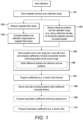
- FIG 1 is a scheme of a calibration method in accordance with some embodiments of the present invention.
- the method comprises starting the calibration, for example a 'calibration mode'.
- the method comprises subsequently moving 101 the magnetic structure over the calibration range.
- the magnetic field is measured 102 with a sensor, thus obtaining at least four measurement signals, and reference positions are obtained 104 over the calibration range.
- measuring 102 the field comprises measuring orthogonal pairs of components of the field, so the obtained signals are representative of two pairs of orthogonal field components, Bx1, Bz1, Bx2, Bz2, obtained at two different positions 1 and 2.
- sensing elements which are configured to provide two orthogonal components in two different positions along the magnetic structure.
- some sensing elements overlap one track with the rest of sensing elements overlap the other track, so the contribution of the field sensed by a group of elements is predominantly due to the master track while the contribution sensed by the other group is dominated by the nonius track.
- some sensing elements may be in a position where the magnetic field includes a large contribution of the master track and a relatively small contribution of the nonius track, and other sensing elements may be in another position where the field shows a relatively large contribution of both tracks.
- the magnetic sensor may comprise Hall elements optionally combined with magnetic concentrators.
- some or all the sensing elements are located above a code-free region disposed between the tracks.
- measuring 102 the field comprises measuring four components of the field in four different positions, for example two pairs of Bz components. These components may be obtained from four sensing elements, where some of them (e.g. two sensing elements) measure the field at a position or positions where the magnetic field includes a large contribution of the master track and a relatively small contribution of the nonius track, and some of them (e.g. two sensing elements) measure the field at other position or positions where the field shows a relatively large contribution of both tracks.
- the field may be measured in a plurality of steps along the calibration range. At least four components of the field are measured in each step. For example, 100 steps, or 200 steps, or 500 steps or more can be measured along the calibration range.
- the calibration range may comprise a whole turn of the encoder (360 degrees). In such case, four measurements of field components are provided in steps of 3 degrees or less than 3 degrees, or 1 degree or less than 1 degree, 0.5 degrees or less than 0.5 degrees, or in steps of 0.1 degrees, or even less than 0.1 degrees, for determining the raw positions for calibration.
- An advantage is that a limited number of steps can be used, so calibration can be fast. In some embodiments, for example, 1000 steps or less, e.g. 500 steps or less , e.g. 300 steps or less, are used.
- the magnetic structure can be moved once over the calibration range (e.g. only one full turn), or can also be moved multiple times over the calibration range.
- the method comprises subsequently determining or computing 103 positions over the calibration range, based on the magnetic field values, for example obtained directly from the measured values of the field, thus these positions are 'raw' or 'uncorrected positions'.
- the raw positions are obtained based on the ratios of the measurement signals (optionally including pre-processing).
- the raw position is not calibrated, and it comprises the error due to cross talk between the tracks, for example.
- obtaining the raw position comprises performing amplitude and phase matching of the measurement signals before obtaining the raw positions, the present invention not being limited thereto.
- the method also comprises receiving 104 reference positions over the calibration range. This can be done as a separate step, for example but not only in parallel. This can be used for example using a reference encoder, which may be an external unit.
- the reference encoder can be of various technologies, e.g. optical, or magnetic.
- the method subsequently comprises the step of deriving 105 position errors over the calibration range (including cross talk error).
- the position error across the calibration range can be minimized, by computing the coefficients of at least one periodic function.
- These coefficients may comprise e.g. amplitude and phase of the periodic function.
- the computation may entail, for example, solving a minimization problem on the position errors over the range. For example, least means squares can be used.
- the coefficients of the periodic function are the correction or calibration coefficients, which are calculated from the available data of the plurality of positions.
- Deriving position errors comprises comparing the raw (or uncorrected) position obtained from the measured magnetic fields and the received reference positions. Deriving the position error can be done in different ways. As a first example, the coefficients can be determined by function matching, so that the raw positions and the periodic function of the raw positions matches the reference positions.
- the data of the raw positions applied to the periodic function is made to match the positions of the reference.
- the coefficients of the correction function can be determined such that the function p_uncorrect - A sin (j.p_uncorrect + B) matches the curve of the reference positions, p_ref (by least squares, curve fitting, regression).
- the coefficients of the periodic function are the amplitude A and phase B, in this particular case.
- the term j can be a harmonic of the function, which may be determined by the magnetic structure, in particular by the number of poles of each track.
- Each periodic function used for providing the calibration coefficients may correspond to a harmonic.
- the coefficients of the at least one correction function are determined such that the error is minimized, for example the coefficients A and B of err - A sin (j.p_uncorrected + B) are optimized such that the error is minimized (e.g. sum of the square of the errors, err ⁇ 2, is as small as possible, the present invention not being limited to that minimization method).
- the coefficients can be programmed 107, or stored, for correcting the raw position during operation of a sensor implemented with the technical means to carry out the method, for example a sensor chip memory.
- the position can be further corrected from cross talk errors, deriving 108 said positions with coefficients computed in the previous steps. This allows to compute the corrected positions, based on said coefficients.
- residual error can be minimized by computing 109 linearization coefficients using previous coefficients.
- the non-linearity errors stem from imperfections in the magnet and such, for example.
- a Look-Up-Table LUT
- LUT Look-Up-Table
- This can be done using a limited number of points defining a piece-wise linear correction function. Then the corrective value is found through interpolation of the LUT points according to the measured position.
- These linearization coefficients can be programmed 110 or stored in the chip.
- computing the coefficients comprises providing a periodic function dependent on the number of pole pairs. Since the number is different, the magnetic field can be described by inclusion of a term with a component from the mismatch of the pairing.
- the periodic function or functions may describe one or more harmonics around a whole period of the calibration range.
- the calibration range may comprise a period wherein a linear magnetic structure repeats its pattern, for example a 360 degree turn.
- the present method can be applied to linear magnetic structures so long as they comprise a master and nonius tracks with different number of pole pairs.
- a periodic function may be dependent on the difference of the number of pole pairs. In some embodiments, a periodic function may be dependent on the sum of the number of pole pairs. Yet in some embodiments, the periodic function may depend on both. For example, two periodic functions can be used, e.g. the combination thereof, each depending on the sum and on the difference of number of pole pairs.
- the calibration can be applied to position sensing in operation.
- An object moves, causing the relative motion between a magnetic sensor and a magnetic structure as described above.
- the position is read by sensing the changes of the field. It is desirable to correct the position sensing by measuring the magnetic field values from the sensor chip, obtaining the position value and, using the calibration coefficients stored in a memory, obtaining the corrected position.
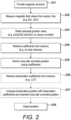
- FIG 2 is a scheme of a position sensing method in accordance with some embodiments of the present invention, wherein the calibration coefficients have been determined.
- the method comprises providing 201 the magnetic structure specified above, and while in operation, measuring 202 field values with the sensor chip. For example, only two values may be required, for example the values corresponding to the magnetic field with relatively small contribution from the nonius track, e.g. Bx1, Bz1.
- the present invention is not limited to this, and a different set of components may be measured.
- the absolute position value is the value of the position after sector determination, thus after combining the information from the nonius track.
- This can be computed or obtained 203 from the sensed values of the magnetic field components, for example by measuring field components, e.g. two components Bx1, Bz1 as mentioned earlier, and two other components with a different set of sensing elements Bx2, Bz2 (e.g. from the sensor where the field has a relatively large contribution from the nonius track).
- the present invention is not limited to this, and the absolute position may be obtained by using a counter. This is shown in FIG 4 . It is advantageous that for the calibration four components are required, but the operation, only a counter and two components may be used, so the counter keeps track of the change of the relative position between the sensor chip and the movable magnetic structure. This reduces processing power and time requirements.
- the stored coefficients are retrieved 204 from a memory, such as a LUT.
- the cross talk corrected position is derived 205 using the measurements and the coefficients.
- the linearization coefficients are retrieved 206 from a memory (e.g. a LUT), if these are available. Using said linearization coefficients and the cross talk corrected position derived earlier, the linearized position can be computed 207 . The signal representative of the position is sent 208 to an output, e.g. another system, a display, memory, etc.
- a memory e.g. a LUT
- each function may correspond to a different harmonic stemming from the field generated by the structure with different number of poles, so that the first function corresponds to a first harmonic (e.g. M-N, where M and N are the number of pole pairs of the master and nonius tracks) and the second function may correspond to a second harmonic (e.g. M+N).
- a first harmonic e.g. M-N, where M and N are the number of pole pairs of the master and nonius tracks
- M+N the second harmonic
- the coefficients correspond to the amplitude and phase of the periodic function.
- a magnetic sensor system is provided. Such system can be used as a position sensor.
- the magnetic structure of the magnetic sensor system moves solidarily with the moveable device, and a magnetic sensor provides the accurate position by implementing the method of embodiments of the previous aspects of the present invention, including e.g. calibration.
- the magnetic sensor system comprises a magnetic sensor and the movable magnetic structure including a master track and nonius track.
- the shape may be any suitable to be used with these sensors, however the number of pole pairs in each track is different.
- the magnetic structure may be any existing structure with multiple periodicities, for example a structure with a master and nonius tracks including a different number of poles.
- the number of pole pairs between master and nonius tracks must have unity as the greatest common divisor.
- the master and nonius tracks of the structure are nested rectangular toroids.
- the magnetic structure comprises two substantially linear strips of magnetic material, spaced from each other by a layer or a zone of a non-magnetic material.
- the non-magnetic material may have a thickness of at least 0.5 mm, or a thickness in the range from about 0.5 mm to 1.5 mm.
- the two strips are separated from each other by means of groove.
- the magnetic sensor includes means to provide four signals representative components of the magnetic field at different positions over the magnetic structure.
- two pairs of sensing elements may be provided.
- Hall sensing elements and magnetic concentrators can be used.
- Other elements may be used, such as magnetoresistive elements and the like, e.g. GMR, TMR, fluxgate sensors, etc.
- the four magnetic components measured in at least two different positions may be e.g. two orthogonal components in each position.
- the magnetic sensor system may comprise a processing unit for processing measurement signals.
- the processing unit may be implemented, for example, as a separate unit, but may be integrated in the sensor chip.
- a memory module, LUT and the like may be included, e.g. also in the sensor chip and connected to the processing unit, to store and retrieve calibration coefficients.
- the magnetic sensor system may comprise a controller for controlling the measurement of the field at a plurality of calibration positions of the magnetic structure.
- the processing unit may also be configured to provide cross talk corrected positions from the coefficients. Similarly, it may be programmed to compute linearization coefficients, and store them in memory.
- the processing unit may also be programmed to apply calibration coefficients to the raw position data calculated during operation thus obtaining the cross talk corrected position.
- the raw position data is also processed by the processing unit.
- the processing unit may also be configured to perform further corrections as described with reference to the method of the previous aspects. For example the processing unit may be programmed to apply, during operation of the sensor, the linearization coefficients if available in a memory. The cross talk corrected position and the linearization coefficients are then used to compute linearized position.
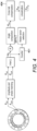
- FIG 3 shows an example of such setup .
- the magnetic structure 301 includes a master track with 8 pole pairs and a nonius track with 7 pole pairs.
- the nonius and master tracks are designed so that the magnetic field has a main contribution from the master track, and the small contribution of the nonius track is sufficient to 'break the symmetry', so it is possible to measure the absolute position with some degree of certainty.
- the magnetic sensor 302 overlaps the magnetic structure, so that one sensing element receives a large contribution from the master track and small contribution from the nonius track, while the other element receives a large contribution from the nonius.
- Each sensing element provides two signals representative of two orthogonal components of the field, for the master track (Bt M , Ba M , for the transversal and axial components respectively) and for the nonius track (Bt N , Ba N ).
- FIG 3 also shows the signal flow from the magnet to the output, for the case of calibration.
- the stages 303 up to 'angle composition' correspond to obtaining the raw position, in this case an angle, from the measurement signals.
- the signals from the sensing elements of the master track (measuring components Bt M , Ba M ) first are processed by amplitude and phase matching, and an angle is calculated (e.g. by the arctan of the ratio of the measured signals).
- the angle includes cross-talk terms ( ⁇ ct ).
- These signals are also linearly combined with the signals from the signal element of the nonius track, and a second angle (linear-combination angle, ⁇ LC ) is calculated.
- a fine angle ⁇ fine is obtained.
- This angle represents the raw angle of the magnetic structure.
- This data treatment may be performed in a processing unit which may be part of the magnetic sensor system.
- the master track has a predetermined number M of pole pairs, and the nonius track has a lower number N than the master track, e.g. one less.
- the two first combinations 1), 2) are the quadrature components (Sin and Cos) of the master track, and the components include the crosstalk components of the second sensor (corresponding to the nonius track).
- the other two combinations 3), 4) are the components of the nonius track, including components also of the measurement from the first sensor, due to the crosstalk.
- the present invention provides a cross-talk compensation 304 where there is no need to extract compensation terms for the measurement signals, by receiving during calibration a limited number of reference positions (angles in this case).
- a limited number of periodic functions are applied to the raw angles and compared to the reference positions, and the error between the raw angle and the reference angle is minimized by any suitable means of data processing, including curve fitting, regression, etc.
- For each function only two coefficients may be needed, being for example the amplitude and phase of the periodic function.
- the minimization of the error results in a calibration angle which can be linearized 305.
- the calibration coefficients (linearized or not) can be stored in a memory.
- FIG 4 shows the signal flow from the magnet to the output during operation.
- the position of the master track is sensed (although it may include cross talk from the nonius track), however in this case a counter 401 can keep track of the position for master sector selection, with no need to process signals from the sensing element corresponding to the nonius track.
- the inverse operation is performed. This time the reference positions are not required.
- the values of the raw position are corrected and compensated 404 using a periodic function, by applying the coefficients stored during calibration. A final step of linearization can be performed.
- FIG 5 is a graph with the residual error after four successive steps of calibration, in a complete turn of the magnetic structure (360 degrees).
- the error is given in mechanical degrees. This error is obtained from the difference between the received reference position and the position computed at each step..
- the curve (a) shows the raw data computed over the calibration range in the absence of amplitude and phase matching of the measurement signals, based on magnetic field values (see FIG 1 ).
- the curve (b) is obtained after deriving the position errors (see corresponding step 105 in FIG 1 ) when amplitude and phase matching is applied to the measurement signals and represents the angular error before applying the calibration method (e.g. input of blocks 304 and 404). The presence of a 1st harmonic and a 15th harmonic can be noticed in the error curve.
- harmonics depend on the number of poles.
- the parameter h indicates the harmonic .
- the calibration coefficients are the amplitude jh and phase ph, for each of the two periodic functions.
- the present invention is not limited to obtaining the periodic functions of two harmonics, only one may be used.
- the lowest harmonic (M-N) may be used, since in general it shows a larger influence in the error.
- cross talk corrected positions Once the cross talk corrected positions have been derived, they can be applied to the raw positions in order to correct them. This can be done in calibration and/or during operation, in the corresponding step of deriving 108, 205 cross-talk corrected position in FIG 1 and FIG 2 .
- the resulting corrected curve (c) is also shown in FIG 5 .
- linearized position can be obtained 207, using linearization errors computed 109 during calibration to minimize residual error.
- the final error is close to 0, as shown in curve (d) in FIG 5 .
- the present invention allows to obtain calibration coefficients with no need to extract the cross-talk components.
- the field is measured for many positions, e.g. hundreds of positions (for a rotatable structure, for example, 720 positions, or positions at a step of 0.5 degree).
- the values of the field e.g. its ratios
- the values of the field are used to directly obtain, without corrections or the like, the values of position, these being the 'uncorrected positions' or raw positions.
- a reference value is obtained. This can be obtained in different ways, for example simultaneously, using a high precision encoder or the like.
- two sets of values are obtained: raw positions and reference positions.
- a periodic function is obtained, wherein its coefficients (e.g.
- the coefficients of the periodic function are the ones stored.
- the periodic function or functions may be for example based on harmonics, for example two functions may be used for two harmonics, based on the number of pole pairs of the tracks (a harmonic for M-N, another for M+N). Only two coefficients are needed per function, and one or two functions may be used, so even if hundreds of positions are measured and compared, in the end only two or four coefficients need to be stored.
- the raw positions measured by the sensing system are corrected by retrieving the coefficients and applying the correction using the periodic functions.
- the method does not require to extract specific information related to cross talk, or the like, but it is not excluded.
- the correction is applied on the angle obtained from the sensor signals, rather than on the sensor signals.
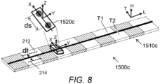
- FIG 6 to FIG 8 shows several magnetic sensing systems which can be used in embodiments of the present invention.
- FIG 6 shows a system 1500a comprising a magnetic structure 1510a comprising two concentric tracks located in a single plane, and a sensor 1520a arranged above or below that plane.
- the first track T1 is formed by an inner ring having eight poles
- the second track T2 is formed by an outer ring having ten poles. These rings are preferably axially magnetized.
- the sensor "sees" eight poles when moving over the inner ring, and “sees” ten poles when moving over the outer ring (or when the sensor is stationary and the magnetic structure is rotated).
- the centrelines 223, 224 of these tracks are two concentric circles having a different radius.
- the centrelines 223, 224 are spaced apart by a track distance "dt" in the radial direction.
- the distance between the sensor locations P1 and P2 of the sensor is "ds", which may be smaller than the track distance "dt", preferably at least 20% smaller.
- the first and second sensor location P1, P2 are preferably located on a virtual line X which is radially oriented with respect to the magnetic structure. There may be an uncoded region, e.g. in the form of a circular groove situated between the tracks T1, T2, optionally filled with a non-magnetic material.
- FIG 7 shows a system 1500b comprising a magnetic structure 1510b comprising two cylindrical tracks having a same radius, and a sensor 1520b arranged as a satellite movable around these cylindrical tracks (or vice versa).
- the centrelines 223, 224 of the first and second track T1, T2 is a first circle and a second circle, a portion of which is shown in FIG. 7 .
- These centrelines 223, 224 are spaced apart by a track distance "dt" in the axial direction A.
- FIG 8 shows a linear system 1500c comprising a magnetic structure 1510c comprising two parallel, linear tracks T1, T2 located in a single plane, and a sensor 1520c arranged above or below that plane. Also shown is an orthogonal coordinate system connected to the magnetic structure, comprising a height direction H, a longitudinal direction L, and a transverse direction T.
- the first track T1 is formed by a first multi-pole magnet having eight poles
- the second track T2 is formed by a second multi-pole magnet having ten poles .
- These magnets are preferably magnetized in the height direction H.
- the sensor 1520c "sees" eight poles (four North poles and four south poles) of the first track T1, and ten poles of the second track T2, when moving over the magnetic structure in the longitudinal direction L (or vice versa).
- the centrelines 223, 224 of these tracks are two parallel lines, spaced apart by a track distance "dt" in the transverse direction T.
- the master and nonius tracks are coplanar tracks, axially magnetized.
- the sensors can be placed above or below the tracks, in a plane parallel to the tracks, so the Z component of the field is the axial direction.
- a sensor chip may include all the sensors, e.g. the sensors may be monolithically integrated with the chip parallel to the tracks. This way, rotating motion of the tracks relative to the sensors are detected as a changing magnetic field and orientation thereof.
- the nonius track may be enclosed by the master track for practical reasons, as the nonius track has lesser of poles than the master track.
- the master track provides a much higher magnetic field than the nonius track, e.g. the maximum magnetic flux density which is 2 times larger, for example 3 or 6 times larger, for at least two components of the field, for example two orthogonal components of the field.
- the master track is made of a magnetic material with a larger magnetization than the nonius track. Many combinations could be envisaged, for example neodymium-based magnets for the master track, with ferrite magnet in the nonius.
- the two tracks may comprise neodymium-based alloys, with a different content of magnetic material.
- the first track may comprise a high content or almost exclusive content of FeNdB, while the second track comprises FeNdB in a plastic matrix (also called plastic bonded magnet), so the content of magnetic material, and ultimately the strength of the second track, are lowered.
- the relative size and geometry of the magnets may be adapted to obtain the desired effect.
- the master track may comprise larger magnets than the nonius track in at least one dimension.
- the tracks of the magnetic structure may have the same thickness and be made of the same materials, which offers mechanical advantages in rotatable systems (e.g.
- FIG 3 shows a master track 306 with 8 pole pairs, where each black zone is a N or S pole.
- the nonius track 307 has 7 pole pairs, where the magnets are much smaller than the magnets of the master track.
- the flux density for the axial and tangential components, sensed by the sensors may be twice larger for the sensing elements of the master track than for the ones of the nonius track, for example the maximum flux density for said components, This can be applied to other configurations of the magnetic tracks, and for different components of the field.
- the first track has an area five times larger than the second track, for example 20 times larger, for example 10 times larger.
- the first track may be for example between 5 times and 50 times larger, for example between 10 times and 30 times larger, than the second track.
- the magnetic structure is a magnetic piece where the tracks are fixed to each other.
- the structure includes a gap between the first and second tracks.
- the gap may be filled with non-magnetic material. The presence of the gap helps reducing crosstalk between the magnetic structures.
Landscapes
- Physics & Mathematics (AREA)
- General Physics & Mathematics (AREA)
- Transmission And Conversion Of Sensor Element Output (AREA)
Priority Applications (2)
| Application Number | Priority Date | Filing Date | Title |
|---|---|---|---|
| EP23206454.3A EP4545910A1 (de) | 2023-10-27 | 2023-10-27 | Positionssensor und kalibrierung |
| PCT/EP2024/080354 WO2025088202A1 (en) | 2023-10-27 | 2024-10-27 | Position sensor and calibration |
Applications Claiming Priority (1)
| Application Number | Priority Date | Filing Date | Title |
|---|---|---|---|
| EP23206454.3A EP4545910A1 (de) | 2023-10-27 | 2023-10-27 | Positionssensor und kalibrierung |
Publications (1)
| Publication Number | Publication Date |
|---|---|
| EP4545910A1 true EP4545910A1 (de) | 2025-04-30 |
Family
ID=88598951
Family Applications (1)
| Application Number | Title | Priority Date | Filing Date |
|---|---|---|---|
| EP23206454.3A Pending EP4545910A1 (de) | 2023-10-27 | 2023-10-27 | Positionssensor und kalibrierung |
Country Status (2)
| Country | Link |
|---|---|
| EP (1) | EP4545910A1 (de) |
| WO (1) | WO2025088202A1 (de) |
Citations (4)
| Publication number | Priority date | Publication date | Assignee | Title |
|---|---|---|---|---|
| EP4170287A1 (de) * | 2021-10-25 | 2023-04-26 | Melexis Technologies SA | Schaltung und verfahren zur bestimmung einer winkelposition |
| EP4187209A1 (de) * | 2021-11-25 | 2023-05-31 | Melexis Technologies SA | Positionssensor mit master- und nonius-spuren |
| EP4019905B1 (de) | 2020-12-23 | 2023-08-16 | Melexis Technologies SA | System und verfahren für einen positionssensor |
| US20230296416A1 (en) * | 2021-11-25 | 2023-09-21 | Melexis Technologies Sa | Position sensor with master and nonius tracks |
-
2023
- 2023-10-27 EP EP23206454.3A patent/EP4545910A1/de active Pending
-
2024
- 2024-10-27 WO PCT/EP2024/080354 patent/WO2025088202A1/en active Pending
Patent Citations (4)
| Publication number | Priority date | Publication date | Assignee | Title |
|---|---|---|---|---|
| EP4019905B1 (de) | 2020-12-23 | 2023-08-16 | Melexis Technologies SA | System und verfahren für einen positionssensor |
| EP4170287A1 (de) * | 2021-10-25 | 2023-04-26 | Melexis Technologies SA | Schaltung und verfahren zur bestimmung einer winkelposition |
| EP4187209A1 (de) * | 2021-11-25 | 2023-05-31 | Melexis Technologies SA | Positionssensor mit master- und nonius-spuren |
| US20230296416A1 (en) * | 2021-11-25 | 2023-09-21 | Melexis Technologies Sa | Position sensor with master and nonius tracks |
Also Published As
| Publication number | Publication date |
|---|---|
| WO2025088202A1 (en) | 2025-05-01 |
Similar Documents
| Publication | Publication Date | Title |
|---|---|---|
| KR101863798B1 (ko) | 개선된 위치 센서 | |
| CN116164778B (zh) | 具有主轨道和诺纽斯轨道的位置传感器 | |
| US8415946B2 (en) | Arrangement and method for magnetic determination of a linear length or a rotary angle | |
| CN114659443B (zh) | 位置传感器系统和方法 | |
| CN108692743B (zh) | 冗余故障检测设备和方法 | |
| US5046031A (en) | Method and apparatus for automatic flux-gate compass calibration | |
| KR20040085075A (ko) | 자기 센서 조정 방법, 자기 센서 조정 장치 및 자기 센서 | |
| KR102195533B1 (ko) | 로터리 인코더 및 로터리 인코더의 각도 보정 방법 | |
| US20170254666A1 (en) | Rotation angle sensor and correction method for the same | |
| Kang et al. | Improving the accuracy of multipole magnetic encoder by three-phase Hall | |
| US20230296416A1 (en) | Position sensor with master and nonius tracks | |
| US11761794B2 (en) | Proximity sensor to sense rotating shaft position and velocity | |
| CN117411371A (zh) | 高精度伺服控制系统 | |
| WO2025088202A1 (en) | Position sensor and calibration | |
| GB2634675A (en) | Multi-track arrangement for linear-or angular-position measuring systems | |
| JP2000258186A (ja) | 自己校正型角度検出装置及び検出精度校正方法 | |
| US11204260B2 (en) | System for determining at least one rotation parameter of a rotating member | |
| EP1016852A1 (de) | Positionssensor | |
| EP4235108B1 (de) | Magnetisches positionssensorsystem mit hoher genauigkeit | |
| CN116259212B (zh) | 一种非接触式磁感应模拟操纵台装置及线性校正方法 | |
| WO2025114272A1 (en) | Angular position sensor with high accuracy, device, magnetic source and system | |
| KR20240134757A (ko) | 자기 각도 위치 센서 최적화 방법 | |
| Al-Jaf et al. | Minimisation of interference between magnetised multipole tracks of magnet disc-based rotation sensors |
Legal Events
| Date | Code | Title | Description |
|---|---|---|---|
| PUAI | Public reference made under article 153(3) epc to a published international application that has entered the european phase |
Free format text: ORIGINAL CODE: 0009012 |
|
| STAA | Information on the status of an ep patent application or granted ep patent |
Free format text: STATUS: THE APPLICATION HAS BEEN PUBLISHED |
|
| AK | Designated contracting states |
Kind code of ref document: A1 Designated state(s): AL AT BE BG CH CY CZ DE DK EE ES FI FR GB GR HR HU IE IS IT LI LT LU LV MC ME MK MT NL NO PL PT RO RS SE SI SK SM TR |
|
| STAA | Information on the status of an ep patent application or granted ep patent |
Free format text: STATUS: REQUEST FOR EXAMINATION WAS MADE |
|
| 17P | Request for examination filed |
Effective date: 20251029 |