EP4546199A1 - Verfahren und vorrichtung zur modellierung eines wärmeverwaltungssystems sowie vorrichtung, medium und fahrzeug - Google Patents
Verfahren und vorrichtung zur modellierung eines wärmeverwaltungssystems sowie vorrichtung, medium und fahrzeug Download PDFInfo
- Publication number
- EP4546199A1 EP4546199A1 EP23826542.5A EP23826542A EP4546199A1 EP 4546199 A1 EP4546199 A1 EP 4546199A1 EP 23826542 A EP23826542 A EP 23826542A EP 4546199 A1 EP4546199 A1 EP 4546199A1
- Authority
- EP
- European Patent Office
- Prior art keywords
- management system
- thermal management
- model
- target
- temperature
- Prior art date
- Legal status (The legal status is an assumption and is not a legal conclusion. Google has not performed a legal analysis and makes no representation as to the accuracy of the status listed.)
- Pending
Links
Images


Classifications
-
- G—PHYSICS
- G06—COMPUTING OR CALCULATING; COUNTING
- G06F—ELECTRIC DIGITAL DATA PROCESSING
- G06F30/00—Computer-aided design [CAD]
- G06F30/20—Design optimisation, verification or simulation
- G06F30/27—Design optimisation, verification or simulation using machine learning, e.g. artificial intelligence, neural networks, support vector machines [SVM] or training a model
-
- G—PHYSICS
- G06—COMPUTING OR CALCULATING; COUNTING
- G06F—ELECTRIC DIGITAL DATA PROCESSING
- G06F30/00—Computer-aided design [CAD]
- G06F30/10—Geometric CAD
- G06F30/15—Vehicle, aircraft or watercraft design
-
- F—MECHANICAL ENGINEERING; LIGHTING; HEATING; WEAPONS; BLASTING
- F01—MACHINES OR ENGINES IN GENERAL; ENGINE PLANTS IN GENERAL; STEAM ENGINES
- F01P—COOLING OF MACHINES OR ENGINES IN GENERAL; COOLING OF INTERNAL-COMBUSTION ENGINES
- F01P7/00—Controlling of coolant flow
- F01P7/14—Controlling of coolant flow the coolant being liquid
- F01P7/16—Controlling of coolant flow the coolant being liquid by thermostatic control
- F01P7/165—Controlling of coolant flow the coolant being liquid by thermostatic control characterised by systems with two or more loops
-
- F—MECHANICAL ENGINEERING; LIGHTING; HEATING; WEAPONS; BLASTING
- F01—MACHINES OR ENGINES IN GENERAL; ENGINE PLANTS IN GENERAL; STEAM ENGINES
- F01P—COOLING OF MACHINES OR ENGINES IN GENERAL; COOLING OF INTERNAL-COMBUSTION ENGINES
- F01P2023/00—Signal processing; Details thereof
-
- F—MECHANICAL ENGINEERING; LIGHTING; HEATING; WEAPONS; BLASTING
- F28—HEAT EXCHANGE IN GENERAL
- F28F—DETAILS OF HEAT-EXCHANGE AND HEAT-TRANSFER APPARATUS, OF GENERAL APPLICATION
- F28F2200/00—Prediction; Simulation; Testing
-
- G—PHYSICS
- G06—COMPUTING OR CALCULATING; COUNTING
- G06F—ELECTRIC DIGITAL DATA PROCESSING
- G06F2113/00—Details relating to the application field
- G06F2113/08—Fluids
-
- G—PHYSICS
- G06—COMPUTING OR CALCULATING; COUNTING
- G06F—ELECTRIC DIGITAL DATA PROCESSING
- G06F2119/00—Details relating to the type or aim of the analysis or the optimisation
- G06F2119/08—Thermal analysis or thermal optimisation
Definitions
- the disclosure belongs to a field of thermal management technology, more particularly, to a method for modeling a thermal management system, an apparatus for modeling a thermal management system, a device for modeling a thermal management system, a readable storage medium, a vehicle, a computer program product and a computer program.
- An automotive thermal management system may automatically adjust a coolant strength according to driving conditions and environmental conditions to keep a corresponding component working within an optimal temperature range, specifically to keep an engine working within a corresponding optimal temperature range.
- an outlet temperature of the coolant is calculated based on a structure of the thermal management system.
- the thermal management system has a complex structure and multiple circulation nodes, resulting in a large workload and a slow speed for calculating the outlet temperature of the coolant.
- a purpose of embodiments of the disclosure is to provide a method for modeling a thermal management system, an apparatus for modeling a thermal management system, a device for modeling a thermal management system, a readable storage medium, a vehicle, a computer program product and a computer program, to simplify the thermal management system thus, enabling to simply and quickly calculate an outlet temperature of coolant.
- a method for modeling a thermal management system includes:
- an apparatus for modeling a thermal management system includes:
- a device for modeling a thermal management system includes: a processor, a memory and programs or instructions stored on the memory and executable by the processor. When the programs or instructions are executed by the processor, the steps of the method for modeling a thermal management system of any embodiment of the first aspect of the disclosure are implemented.
- a computer-readable storage medium having programs or instructions stored thereon is provided.
- the programs or instructions are executed by a processor, the steps of the method for modeling a thermal management system of any embodiment of the first aspect of the disclosure are implemented.
- a vehicle includes at least one of:
- a computer program product including a computer program is provided.
- the computer program is executed by a processor, the method for modeling a thermal management system of any embodiment of the first aspect of the disclosure is implemented.
- a computer program including computer program codes is provided.
- the computer program codes are executed by a computer, the computer is caused to implement the method for modeling a thermal management system of any embodiment of the first aspect of the disclosure.
- the apparatus for modeling a thermal management system, the device for modeling a thermal management system, the medium and a vehicle provided by the embodiments of the disclosure, the plurality of temperature nodes in the thermal management system and the plurality of branch loops in the thermal management system are obtained, and the temperature nodes that satisfy a preset condition but are unable to be combined in the thermal management system are determined based on the heat exchange component in each of the plurality of branch loops and/or the warm water points of the coolant in at least two of the plurality of branch loops.
- the target model corresponding to the thermal management system is obtained by combining the plurality of temperature nodes in the thermal management system according to the preset combination policy based on the temperature nodes that are unable to be combined.
- the number of temperature nodes in the finally obtained target model is less than the number of temperature nodes in the thermal management system at the beginning, which simplifies a structure of the thermal management system. In this way, when calculating an outlet water temperature in the thermal management system, there is no need to calculate the temperatures of too many temperature nodes, thereby improving a calculation efficiency of the outlet water temperature and saving computing power.
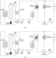
- FIG. 1 is an overall model of a thermal management system of a vehicle.
- the connecting lines between heat exchange components in FIG. 1 may indicate a flow direction of coolant.
- the calculation of an outlet temperature of the coolant is based on a structure of the thermal management system.
- the structure of the thermal management system is complex and contains multiple circulation nodes, e.g., circulation nodes at both ends of the battery (T6.2 and T6.1), circulation nodes at both ends of the fan heat exchanger (T6.3 and T6.4), and circulation nodes at both ends of the engine (T1.1 and T1.2) in FIG. 2 .
- the temperature of each circulation node is calculated first according to a flow direction of the coolant, and then the outlet temperature is calculated. For example, as shown in FIG. 2 , the temperatures at both ends of the engine are calculated at first. Then, according to the flow direction of the coolant, the temperature at the temperature node T3 is calculated, the temperature at the temperature node T2.1 and the temperature at the temperature node T2.3 are calculated, and the temperature at the temperature node T2.2 is calculated according to the temperature at the temperature node T2.1.
- the outlet temperature of the coolant is calculated. In this way, the calculation amount is large and the calculation speed is slow.
- embodiments of the disclosure provide a method for modeling a thermal management system, an apparatus for modeling a thermal management system, a device for modeling a thermal management system, a readable storage medium, a vehicle, a computer program product and a computer program.
- a target model corresponding to the thermal management system is obtained by combining the temperature nodes in the thermal management system according to a preset combination policy based on the temperature nodes that are unable to be combined. Since the temperature nodes in the thermal management system can be combined continuously according to the preset combination policy, a number of temperature nodes in the target model finally obtained is less than a number of temperature nodes in the thermal management system at the beginning, which simplifies the structure of the thermal management system. In this way, when calculating an outlet water temperature in the thermal management system, there is no need to calculate the temperatures of too many temperature nodes, thereby improving the calculation efficiency of the outlet water temperature and saving computing power.
- the method for modeling a thermal management system is based on detecting an outlet temperature of the coolant at the engine and the outlet temperature of the coolant at the battery in FIG. 1 .
- FIG. 3 is a flowchart of a method for modeling a thermal management system provided by an embodiment of the disclosure.
- An execution subject of the method for modeling a thermal management system may be a server. It should be noted that the above execution subject does not constitute a limitation of the disclosure.
- the method for modeling a thermal management system may include steps 310-330.
- a plurality of temperature nodes in the thermal management system of a vehicle and a plurality of branch loops in the thermal management system are obtained.
- temperature nodes that are unable to be combined in the thermal management system are determined based on a heat exchange component in each of the plurality of branch loops and/or warm water points of coolant in at least two of the plurality of branch loops.
- a target model corresponding to the thermal management system is obtained by combining the plurality of temperature nodes in the thermal management system according to a preset combination policy based on the temperature nodes that are unable to be combined in the thermal management system.
- the plurality of temperature nodes in the thermal management system and the plurality of branch loops in the thermal management system are obtained, and the temperature nodes that satisfy a preset condition but are unable to be combined in the thermal management system are determined based on the heat exchange component in each of the branch loops and/or the warm water points of the coolant in at least two of the plurality of branch loops.
- the target model corresponding to the thermal management system is obtained by combining the plurality of temperature nodes in the thermal management system according to the preset combination policy based on the temperature nodes that are unable to be combined.
- the number of temperature nodes in the finally obtained target model is less than the number of temperature nodes in the thermal management system at the beginning, which simplifies a structure of the thermal management system. In this way, when calculating an outlet water temperature in the thermal management system, there is no need to calculate the temperatures of too many temperature nodes, thereby improving a calculation efficiency of the outlet water temperature and saving computing power.
- a plurality of temperature nodes in the thermal management system of a vehicle and a plurality of branch loops in the thermal management system are obtained.
- the temperature nodes may be nodes calculated in the thermal management system when calculating an outlet temperature of coolant, e.g., the circulation nodes at both ends of the battery, the circulation nodes at both ends of the fan heat exchanger, and the circulation nodes at both ends of the engine in FIG. 1 .
- the branch loop may be a circulation loop formed by the circulation of the coolant in the thermal management system.
- many loops can be formed in FIG. 1 , such as, a loop of battery-fan heat exchanger- battery, a loop of battery- heat exchanger-battery, and a loop of heat exchanger-air cooling and heating system-three-way valve-heat exchanger.
- temperature nodes that are unable to be combined in the thermal management system are determined based on a heat exchange component in each of the plurality of branch loops and/or warm water points of coolant in at least two of the plurality of branch loops.
- the temperature nodes that are unable to be combined in the thermal management system can be determined according to the heat exchange component in each branch loop. In detail, if a certain branch loop has a heat exchange component, it can be determined that the temperature nodes at both ends of the heat exchange component in the branch loop are unable to be combined.
- the temperature nodes that are unable to be combined in the thermal management system can be determined according to the warm water points of the coolant in at least two branch loops. In detail, if the coolant in the at least two branch loops are mixed together, it is determined that the temperature nodes of the at least two branch loops are unable to be combined.
- a water mixing point between a water pump and the fan heat exchanger in FIG. 2 is a water mixing point of both the branch loop of battery-fan heat exchanger-battery and a branch loop of fan heat exchanger-heat exchanger-fan heat exchanger, and thus a temperature node T6.5 and a temperature node T6.8 are unable to be combined.
- a target model corresponding to the thermal management system is obtained by combining the plurality of temperature nodes in the thermal management system according to a preset combination policy based on the temperature nodes that are unable to be combined in the thermal management system.
- the preset combination policy may be a preset policy for combining temperature nodes that are unable to be combined in the thermal management system.
- the step 330 may include steps 3301-3304.
- a delay volume corresponding to the heat exchange component in each branch loop is established based on the temperature nodes that are unable to be combined in the thermal management system.
- the delay volume corresponding to the heat exchange component in each branch loop may be established according to the temperature nodes that are unable to be combined in the thermal management system.
- step 3301 in order to accurately establish the delay volume corresponding to the heat exchange component in each branch loop, may include:
- An input of the open-loop model is a control parameter value of the thermal management system at a k th moment.
- the control parameter value may be a value of a control parameter for controlling operation of the thermal management system, and a specific control parameter value is described in detail in the following embodiments.
- An output of the open-loop model is a temperature of the thermal management system at the k th moment.
- the N initial volumes one-to-one corresponding to the plurality of branch loops can be determined by comparing a temperature at a certain moment predicted by the open-loop model with an actual temperature at the certain moment.
- the open-loop model can be converted into a closed-loop model, which is a model for predicting a temperature at a future moment.
- the closed-loop model is used to modify an initial volume corresponding to each branch loop to obtain a delay volume corresponding to each branch loop.
- a specific modification method may be comparing a temperature of a certain branch loop predicted by the closed-loop model with an actual temperature of the certain branch loop, and modifying the initial volume based on a comparison result.
- the reliability of determining the delay volume corresponding to each branch loop can be improved.
- a purpose of the delay volume is to simulate a delay between two temperature nodes.
- the N initial volumes one-to-one corresponding to the plurality of branch loops in the thermal management system are determined according to the open-loop model.
- the open-loop model is closed, and the N delay volumes corresponding to the plurality of branch loops in the thermal management system are obtained by modifying the N initial volumes with the closed open-loop model.
- the N delay volumes one-to-one corresponding to the plurality of branch loops can be obtained accurately, thereby improving the reliability of determining the delay volume corresponding to each branch loop.
- a first model corresponding to the thermal management system is obtained by simplifying the heat exchange component in each branch loop of the thermal management system based on the delay volume corresponding to the heat exchange component in each branch loop.
- the first model may be a simplified model of the thermal management system obtained by simplifying the heat exchange component in each branch loop of the thermal management system based on the delay volume corresponding to the heat exchange component in each branch loop.
- one or more heat exchange components in each branch loop of the thermal management system can be simplified according to the one or more delay volumes corresponding to the one or more heat exchange components in each branch loop established as described above, so as to obtain the first model corresponding to the thermal management system shown in FIG. 4 .
- the air cooling and heating system is not working, thus the air cooling and heating system and the heat exchanger can be combined together to obtain the virtual volume V5 in FIG. 4 .
- the virtual volume V1 is from T2.1 to T2.3, which passes through T2.2 and includes a fan heat exchanger.
- the virtual volume V2 is from T4.1 to T4.6, which passes through T4.2-T4.5 and includes a cooling and heating system.
- the virtual volume V3 is from T4.6 to T4.9/T4.10, which passes through T4.7 and T4.8 and includes a heat exchanger and a three-way valve.
- the virtual volume V4 is from T4.9 to T6.3/T6.6, which passes through T6.1 and T6.2 and includes a battery.
- the virtual volume V5 is from T6.3 to T6.5, which passes through T6.4 and includes a battery and a fan heat exchanger.
- the virtual volume V6 is from T6.6 to T6.8, which passes through T6.7 and includes a heat exchanger.
- a second model corresponding to the thermal management system is obtained by combining temperature nodes having a same temperature in different branch loops in the first model.
- the second model may be a simplified model of the thermal management system obtained by combining the temperature nodes having the same temperature in different branch loops in the first model.
- the temperature nodes T1.2, T2.1 and T3.2 belong to different branch loops, and their temperatures are the same without heat conduction. Therefore, the temperature nodes T1.2, T2.1 and T3.2 in FIG. 5 can be combined.
- the temperature nodes T6.6 and T6.3 in FIG. 4 belong to different branch loops, and their temperatures are the same without heat conduction. Therefore, the temperature nodes T6.6 and T6.3 in FIG. 4 can be combined.
- the temperature nodes T1.1 and T5 in FIG. 4 belong to different branch loops, and their temperatures are the same without heat conduction. Therefore, the temperature nodes T6.6 and T6.3 in FIG. 4 can be combined. In this way, the second model shown in FIG. 5 can be obtained.
- the target model corresponding to the thermal management system is obtained by combining two adjacent water mixing points without heat conduction in the second model into one water mixing point.
- the target model may be a simplified model of the thermal management system obtained by combining two adjacent water mixing points without heat conduction in the second model into one water mixing point.
- a water mixing point 1 and a water mixing point 2 are two adjacent water mixing points, there is no heat conduction between them, and neither an outlet temperature node of the engine or an outlet temperature node of the battery to be calculated is located between the water mixing point 1 and the water mixing point 2, therefore, the water mixing point 1 and the water mixing point 2 can be combined into one water mixing point, and the target model shown in FIG. 6 is obtained.
- the method for modeling a thermal management system may further include:
- the first target branch loop may be at least one of the branch loops.
- the local flow model of the first target branch loop can be established based on the flow relation between the branch loops in the first target model.
- the flow corresponding to the first target branch loop can be calculated based on the local flow model.
- the temperature of the first target branch loop can be accurately determined according to the flow corresponding to the first target branch loop and the temperature delay model corresponding to the delay volume of the first target branch loop.
- establishing the local flow model of the first target branch loop based on the flow relation between the branch loops in the target model includes:
- branch loops there are 8 branch loops (i.e., Q1-Q8 in FIG. 6 ) in the target model shown in FIG. 6 .
- the local flow models of only 4 branch loops may be established.
- the local flow models of the branch loops Q1, Q2, Q6 and Q7 may be established.
- different types of heat exchange components have different methods for establishing a local flow model. Therefore, when establishing a local flow model of the first target branch loop, a local flow model corresponding to a type of a heat exchange component in the first target branch loop may be established according to the type of the heat exchange component in the first target branch loop.
- the first target branch loop can be determined based on the number of branch loops in the first target model and the flow equation between the branch loops in the first target model. Based on the type of the heat exchange component in the first target branch loop, the local flow model corresponding to the type of the heat exchange component in the first target branch loop is established, so that the local flow model corresponding to the first target branch loop can be accurately established, and an accurate outlet temperature of the first target branch loop is obtained.
- establishing the local flow model corresponding to the type of the heat exchange component in the first target branch loop includes:
- the historical operating condition parameter may be an operating condition parameter of the engine before predicting a temperature of a cooling system of the engine at this time.
- the first correspondence equation may be an equation of the heat exchange coefficient between the operating condition parameter of the engine and the combustion gas.
- the second correspondence equation may be an equation of the heat exchange coefficient between the mass flow of the coolant and the cylinder wall of the engine.
- the functional relation between the temperature of the combustion gas and the operating condition parameter of the engine may be a local flow model established corresponding to the type of the heat exchange component in the target branch loop.
- a heat exchange model of the engine may be simplified.
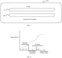
- the heat exchange model of the engine may be simplified to a double-layer flat plate heat exchange model (as shown in FIG. 7 ).
- the combustion gas (not shown) is inside the engine 700
- the coolant (not shown) is between an inner cylinder wall 710 and an outer cylinder wall 720.
- the combustion gas is burned, heat flows into the inner cylinder wall 710 through convective heat exchange and heats the inner cylinder wall 710.
- the inner cylinder wall 710 in turn heats the coolant.
- the temperature of the coolant raises after obtaining energy, and heats the outer cylinder wall 720. Meanwhile, spontaneous convective heat exchange occurs between the outer cylinder wall and the external environment.
- a cover of the cylinder is in one piece with the inner cylinder wall, and there is no heat conduction between the cover and the outer cylinder wall.
- the cylinder wall can be heated uniformly without considering the internal temperature difference.
- ⁇ 1 is the heat exchange coefficient between the operating condition parameter of the engine and the combustion gas
- n is a rotation speed of the engine
- T is a torque of the engine
- a1, b1, c1, d1, f1 and h1 are all constants that are determined based on the type of the engine.
- the function between the temperature of the combustion gas and the operating condition parameter of the engine is obtained by fitting, based on the double-layer flat plate model corresponding to the engine, the first correspondence equation and the second correspondence equation according to the steady-state heat exchange conservation equation between the coolant in the engine and the combustion gas.
- the functional relation between the temperature of the combustion gas and the operating condition parameter of the engine can be calculated based on the heat exchange coefficient without the need for other redundant calculations, thereby improving the calculation efficiency of the functional relation between the temperature of the combustion gas and the operating condition parameter of the engine, and further improving the efficiency of determining the outlet temperature of the target branch loop.
- obtaining the function between the temperature of the combustion gas and the operating condition parameter of the engine by fitting, based on the double-layer flat plate model corresponding to the engine, the first correspondence equation and the second correspondence equation according to the steady-state heat exchange conservation equation between the coolant in the engine and the combustion gas includes:
- the third equation may be a correspondence equation among the combustion gas, the inlet temperature of the coolant and the outlet temperature of the coolant.
- the temperature of the outer cylinder wall of the engine is very close to the temperature of the coolant. Therefore, it is considered that the amount of heat exchanged between the coolant and the outer cylinder wall is very small and has little effect on the change in the temperature of the coolant.
- the heat exchange between the coolant and the inner cylinder wall is mainly considered.
- the first correspondence equation and the second correspondence equation are fitted according to the heat exchange area between the inner cylinder wall and the combustion gas, the heat exchange area between the inner cylinder wall and the coolant, and the heat conduction area of the inner cylinder wall.
- Equation (5) T gas ⁇ T w / 1 1 ⁇ 1 ⁇ A 1 + 1 ⁇ 1 ⁇ A 2 + 1 ⁇ 2 ⁇ A 3
- T gas is the temperature of the combustion gas
- T w is the temperature of the coolant
- A1 is the heat exchange area between the combustion gas and the inner cylinder wall
- A2 is the heat conduction area of the inner cylinder wall
- A3 is the heat exchange area between the inner cylinder wall and the coolant
- ⁇ 1 is a heat conduction coefficient of the inner cylinder wall, which is a constant relating to the material of the inner cylinder wall
- ⁇ 1 is the heat exchange coefficient between the operating condition parameter of the engine and the combustion gas
- ⁇ 2 is the heat exchange coefficient between the mass flow of the coolant and the cylinder wall of the engine.
- equations (7) and (8) are combined, and the length from the inlet to the outlet of the inner cylinder wall in the engine is accumulated to obtain the third equation (i.e., equation (9)) among the combustion gas, the inlet temperature of the coolant and the outlet temperature of the coolant:
- Q m ⁇ ⁇ C p ⁇ dT w
- C p is a specific heat at constant pressure of the coolant
- ⁇ is the mass flow of the coolant of the engine
- dT w is a difference between the inlet temperature and the outlet temperature of the coolant.
- L c is a characteristic length of the heat exchange component (e.g., the inner cylinder wall, the coolant, the combustion gas, or the outer cylinder wall), which indicates the heat exchange area corresponding to each unit length;
- x is a length of the heat exchange component;
- ⁇ 1 / 1 ⁇ 1 + 1 ⁇ 1 + 1 ⁇ 2 ;
- T gas is the temperature of the combustion gas; and
- T w is the temperature of the coolant.
- T gas is the temperature of the combustion gas
- T w, out is a water outlet temperature of the coolant
- T w,in is a water inlet temperature of the coolant
- m is water mass
- ⁇ 1 / 1 ⁇ 1 + 1 ⁇ 1 + 1 ⁇ 2
- C p is the specific heat at constant pressure of the coolant.
- T gas T w , out ⁇ N ⁇ T w , in / 1 ⁇ N
- T gas the temperature of the combustion gas
- T w, out the water outlet temperature of the coolant
- T w,in the water inlet temperature of the coolant
- the steady-state experimental data can be obtained to calculate T gas corresponding to each operating condition, so that a correspondence among the rotation speed and the torque of the engine and the combustion gas temperature is obtained.
- T gas a ⁇ n 2 ⁇ b ⁇ T 2 ⁇ c ⁇ n ⁇ T + d ⁇ n + f ⁇ T + h
- T gas is a virtual combustion gas temperature
- n is the rotation speed of the engine
- T is the torque of the engine
- a, b, c, d, f and h are constants that are determined based on the type of the engine.
- the engine under the steady-state condition, the engine has reached a stable high temperature, so that an air inlet temperature at the beginning of the combustion is higher than an air inlet temperature for cold start.
- the water inlet temperature is used to represent different cold start stages to modify this phenomenon.
- T gas a ⁇ n 2 ⁇ b ⁇ T 2 ⁇ c ⁇ n ⁇ T + d ⁇ n + f ⁇ T + h T w , in T w , in , measure
- T w,in is the air inlet temperature for cold start
- T w,in,measure is the air inlet temperature at the beginning of combustion.
- the heat conduction thermal resistance equation within the engine is obtained by fitting the first correspondence equation and the second correspondence equation.
- the third equation among the combustion gas, the inlet temperature of the coolant and the outlet temperature of the coolant is obtained.
- the function between the combustion gas temperature and the operating condition parameter of the engine is obtained by performing a quadratic function fitting on the third equation and the operating condition parameter of the engine.
- establishing the local flow model corresponding to the type of the heat exchange component in the first target branch loop includes:
- the first flow data can be key flow data of the thermal management system obtained during an experiment process, which can be overall flow data of the thermal management system, or local flow data of a certain key heat exchange component (e.g., a battery or an engine) in the thermal management system in FIG. 1 .
- a certain key heat exchange component e.g., a battery or an engine
- an overall physical model i.e., the physical model in FIG. 1 , corresponding to the thermal management system can be established by obtaining the first flow data of the thermal management system.
- the model parameters of the physical model may be a water pump pressure rise of the coolant, a pressure drop of heat exchange environment, and a loss of the coolant along the pipe wall, etc., which are used when establishing the physical model.
- the preset model may be a model set in advance. After performing the training on the preset model, a local flow model for determining a local flow of the coolant at the target heat exchange component can be obtained.
- the preset model may be a neural network model, or other models that can be used to predict the local flow at the target heat exchange component, which is not limited here.
- the target heat exchange component may be a heat exchange component for predicting the local flow, for example, may be the battery or the water pump in FIG. 1 .
- the target physical model can be a physical model corresponding to the thermal management system obtained by modifying the model parameters of the physical model.
- model parameters of the physical model may be modified manually by an engineer, or may be automatically modified by other means, which is not limited here.
- the target characteristic parameter may be a characteristic parameter for controlling the operation of the thermal management system or a characteristic parameter obtained after a preset processing is performed on the characteristic parameter for controlling the operation of the thermal management system.
- the physical model corresponding to the thermal management system is established based on the obtained first flow data of the thermal management system.
- the target physical model corresponding to the thermal management system is obtained by modifying the model parameter of the physical model based on the first flow data.
- the second flow data of the coolant at the target heat exchange component in the thermal management system is calculated.
- the training samples are generated according to the second flow data and its corresponding target characteristic parameter for controlling the operation of the thermal management system.
- the local flow model for determining the local flow of the coolant at the target heat exchange component is obtained by performing training on the preset model based on the training samples.
- the local flow model for accurately calculating the local flow of the coolant can be obtained, and the established local flow model can obtain the local flow of the coolant at the target component. Therefore, the calculation is simple and fast, and the obtained local flow of the coolant at the target component is accurate, which improves the accuracy and efficiency of obtaining the local flow of the coolant at the target component.
- the method for modeling a thermal management system involved above may further include:
- the first characteristic parameter may be a direct characteristic parameter for controlling the operation of the thermal management system, such as a rotation speed of the water pump, a temperature, a valve opening degree, a rotation speed of the engine, and a torque of the engine.
- the associated characteristic parameter may be a characteristic parameter obtained by expanding the first characteristic parameter according to a correspondence between the first characteristic parameter and the first flow data.
- the first characteristic parameter may include a rotation speed of the water pump, a temperature, a valve opening degree, a rotation speed of the engine, and a torque of the engine.
- the associated characteristic parameters of the rotation speed of the water pump can be obtained, such as, a square of the rotation speed and a cube of the rotation speed.
- the associated characteristic parameters of the temperature can be obtained, such as, a square of the temperature, a cubic of the temperature and a fourth power of the temperature.
- the valve opening degree the associated characteristic parameters of the valve opening degree can be obtained, such as, a square of the valve opening degree and a cubic of the valve opening degree.
- the associated characteristic parameters of the rotation speed and the torque of the engine can be obtained, such as, a product of the rotation speed and the torque of the engine, and an integral of the product of the rotation speed and the torque of the engine.
- the target characteristic parameter may be a characteristic parameter based on each associated characteristic parameter, for example, a characteristic parameter obtained by performing a preset processing on each associated characteristic parameter.
- the preset model may be model set in advance. After performing training on the preset model, the local flow model for determining the local flow of the coolant at the target heat exchange component may be obtained.
- the first characteristic parameter for controlling the operation of the thermal management system is obtained. According to the correspondence between the first characteristic parameter and the first flow data, the at least one associated characteristic parameter associated with the first flow data is determined. According to each associated characteristic parameter, the target characteristic parameter is determined. In this way, the target characteristic parameter can be accurately determined, and the local flow model for determining the local flow of the coolant at the target heat exchange component can be accurately established.
- determining the target characteristic parameter according to each associated characteristic parameter may include following steps.
- Step A each associated characteristic parameter is input into a feature screening model sequentially, and a predicted flow value corresponding to each associated characteristic parameter is obtained.
- Step B for each associated characteristic parameter, a mean square error between the predicted flow value corresponding to the associated characteristic parameter and a low flow value of the coolant in the thermal management system is calculated.
- Step C an associated characteristic parameter corresponding to the minimum mean square error is determined as a first candidate characteristic parameter.
- Step D an output of the feature screening model is updated to a high flow value of the coolant in the thermal management system, and steps A to C are performed again to obtain a second candidate characteristic parameter.
- Step E the first candidate characteristic parameter and the second candidate characteristic parameter are determined as target characteristic parameters.
- the feature screening model may be obtained by learning a relation between each associated characteristic parameter and a flow value of the coolant in the thermal management system.
- the feature screening model may be a generalized regression neural network (GRNN) based on joint probability distribution.
- An input of the model can be various associated characteristic parameters, and an output can be a flow value of the coolant in the thermal management system.
- GRNN generalized regression neural network
- the predicted flow value may be a flow value corresponding to each associated characteristic parameter predicted by the feature screening model based on each associated characteristic parameter after inputting each associated characteristic parameter into the feature screening model sequentially.
- the low flow value may be a flow value that is less than or equal to a first preset flow threshold.
- the low flow value may be a lower flow value within a flow range of the coolant.
- the first preset flow threshold may be a preset threshold of the low flow value. For example, if the flow range of the coolant is between 500 and 1000, the low flow value may be between 500 and 700.
- the first candidate characteristic parameter may be an associated characteristic parameter corresponding to the minimum mean square error in the mean square errors between the predicted flow values corresponding to the respective calculated associated characteristic parameters and the low flow value of the coolant in the thermal management system.
- the high flow value may be a flow value greater than or equal to a second preset flow threshold.
- the high flow value may be a higher flow value within the flow range of the coolant.
- the second preset flow threshold may be a preset threshold of the high flow value. For example, if the flow range of the coolant is between 500 and 1000, the high flow value may be between 700 and 1000.
- the associated characteristic parameters include the product of the rotation speed and the torque of the engine, the square of a rotation speed of the water pump and a cubic of the rotation speed of the water pump, all the associated characteristic parameters are traversed. That is, the product of the rotation speed and the torque of the engine, the square of the rotation speed of the water pump and the cubic of the rotation speed of the water pump are input into the feature screening model respectively, and the predicted flow values corresponding to the product of the rotation speed and the torque of the engine, the square of the rotation speed of the water pump and the cubic of the rotation speed of the water pump are respectively obtained.
- determining the temperature of the first target branch loop based on the flow corresponding to the first target branch loop and the temperature delay model corresponding to the delay volume of the first target branch loop includes:
- An input of the temperature delay model for flow accumulation of a certain branch loop is a delay flow value of the branch loop at a certain moment, and an output is the temperature of the outlet of the branch loop at the certain moment.
- the accumulated flow value of the branch loop at a certain moment may be a sum of the flow value at the certain moment and a historical flow value.
- the historical flow value at a certain moment is a sum of flow values from the initial moment to a previous moment of the certain moment.
- a flow value at a certain moment can be determined based on a control parameter value at the certain moment and can be obtained based on the above local flow model in implementations.
- the temperature delay model for flow accumulation can be understood as a model based on table searching. For ease of understanding, as illustrated in FIG. 8 , when determining the temperature at a certain moment, the accumulated flow value at the certain moment can be determined first, and then based on the delay volume, a delay flow value at the certain moment is determined. At last, a temperature corresponding to the delay flow value is determined as the temperature at the certain moment.
- the temperature delay model for flow accumulation is updated in real time during an iterative calculation process.
- the temperature delay model for flow accumulation is updated every time an iterative operation is performed.
- a temperature of the i th branch loop may affect the update of the temperature delay model for flow accumulation of the (i+1) th branch loop, thereby improving the reliability of the prediction.
- a second temperature of the thermal management system at the second moment can be understood as an output temperature of the N th branch loop. Therefore, in this embodiment, after updating the temperature delay model for flow accumulation corresponding to each branch loop, an accumulated flow value of the P th branch loop at the first moment can be calculated, to consider the influence of heat conduction delay. Based on the accumulated flow value and the virtual volume of the P th branch loop, a delay flow value of the P th branch loop at the first moment can be determined and input into the temperature delay model for flow accumulation corresponding to the P th branch loop, to obtain an output temperature of the P th branch loop, i.e., the second temperature of the thermal management system at the second moment.
- the temperature delay model for flow accumulation corresponding to the first target branch loop is updated based on the first temperature of the thermal management system at the first moment, the flow value of the first target branch loop at the first moment and the delay volume corresponding to the first target branch loop.
- the delay flow value of the first target branch loop at the first moment is determined according to the flow value of the first target branch loop at the first moment and the delay volume corresponding to the first target branch loop.
- the temperature corresponding to the delay flow value of the first target branch loop at the first moment is determined as the temperature of the first target branch loop at the second moment, so that the temperature of the first target branch loop at the second moment can be accurately determined.
- updating the temperature delay model for flow accumulation corresponding to the first target branch loop based on the first temperature of the thermal management system at the first moment, the flow value of the first target branch loop at the first moment and the delay volume corresponding to the target branch loop includes:
- u is an integer greater than or equal to 1 and less than N; N is a number of branch loops in the target model; when u is equal to 1, for the second target branch loop, the target object may be the first temperature.
- the target object may be the output temperature of the second target branch loop at the second moment.
- the output temperature of the second target branch loop at the second moment is determined based on the flow value of the second target branch loop at the first moment, the delay volume corresponding to the second target branch loop, and the temperature delay model for flow accumulation corresponding to the updated second target branch loop.
- a first reference temperature may be calculated according to the first temperature and the flow value of the first branch loop at the first moment, and the temperature delay model for flow accumulation corresponding to the first branch loop is updated according to the first reference temperature, and the flow value of the first branch loop at the first moment.
- an accumulated flow value of the first branch loop at the first moment can be determined according to the flow value of the first branch loop at the first moment and a historical flow value of the first branch loop at the first moment.
- a delay flow value of the first branch loop at the first moment can be determined according to the accumulated flow value of the first branch loop at the first moment and the delay volume corresponding to the first branch loop.
- the delay flow value of the first branch loop at the first moment and the first reference temperature may be added to the temperature delay model for flow accumulation corresponding to the first branch loop.
- a first point may be added to the curve.
- a horizontal coordinate corresponding to the first point is the delay flow value of the first branch loop at the first moment, and a vertical coordinate corresponding to the first point is the first reference temperature.
- the second reference temperature can be calculated according to the output temperature of the first branch loop at the second moment and the flow value of the second branch loop at the first moment. According to the second reference temperature and the flow value of the second branch loop at the first moment, the temperature delay model for flow accumulation corresponding to the first branch loop is updated.
- the output temperature of each branch loop can be determined based on the temperature delay model for flow accumulation of each branch loop.
- the output temperature of the first branch loop at the second moment can be determined according to the flow value of the first branch loop at the first moment, the delay volume corresponding to the first branch loop, and the updated temperature delay model for flow accumulation corresponding to the first branch loop.
- the specific determination method can be referred to the above-mentioned related description, which will not be repeated here.
- the updating of the temperature delay models for flow accumulation corresponding to other branch loops can be similar to the updating of the temperature delay model for flow accumulation corresponding to the second branch loop, and is not described in detail here to avoid repetition.
- the temperature delay model for flow accumulation corresponding to each branch loop can be updated, thereby improving the reliability of temperature prediction.
- the reference temperature can be obtained by searching a table.
- the reference temperature may be obtained based on a model.
- calculating the reference temperature of the first target branch loop according to the target object and the flow value of the first target branch loop at the first moment may include: obtaining the reference temperature of the first target branch loop by inputting the target object and the flow value of the first target branch loop at the first moment into a heat exchange model corresponding to the first target branch loop.
- the heat exchange model is configured to:
- a heat exchange model may be set for each branch loop respectively, and the temperature delay model for updating flow accumulation corresponding to a certain branch loop may be determined based on the heat exchange model of the certain branch loop.
- the first value may be a ratio of the flow value of the first target branch loop at the first moment to the characteristic length corresponding to the branch loop, so that the lack of flow accuracy can be compensated, thereby improving the reliability of temperature prediction.
- the characteristic length can be understood as a heat exchange area corresponding to a unit length.
- the characteristic lengths corresponding to different branch loops may be different, which may be set according to the experimental data.
- a heat exchange component (for example, the heat exchange component is a battery in the battery branch) can conduct heat to the coolant to cause the temperature of the coolant to change.
- the change in the heat of the coolant caused by the change of temperature is shown in the above equation (7).
- the output temperature of the branch loop can be determined according to the characteristic length corresponding to the branch loop, so that the lack of flow accuracy can be compensated, thereby improving the reliability of temperature prediction.
- the method for modeling a thermal management system may be executed by an apparatus for modeling a thermal management system, or a control module in the apparatus for modeling a thermal management system may be used for executing the method for modeling a thermal management system.
- the disclosure also provides an apparatus for modeling a thermal management system.
- the apparatus for modeling a thermal management system provided by the embodiment of the disclosure is described in detail below with reference to FIG. 9 .
- FIG. 9 is a schematic diagram of an apparatus for modeling a thermal management system provided by an embodiment of the disclosure.
- the apparatus 900 for modeling a thermal management system includes: a first obtaining module 910, a first determining module 920, and a second determining module 930.
- the first obtaining module 910 is configured to obtain a plurality of temperature nodes in the thermal management system of a vehicle and a plurality of branch loops in the thermal management system.
- the first determining module 920 is configured to determine temperature nodes that are unable to be combined in the thermal management system based on a heat exchange component in each of the plurality of branch loops and/or warm water points of coolant in at least two of the plurality of branch loops.
- the second determining module 930 is configured to obtain a target model corresponding to the thermal management system by combining the plurality of temperature nodes in the thermal management system according to a preset combination policy based on the temperature nodes that are unable to be combined in the thermal management system.
- the first obtaining module obtains the plurality of temperature nodes in the thermal management system and the plurality of branch loops in the thermal management system.
- the first determining module determines the temperature nodes that satisfy a preset condition but are unable to be combined in the thermal management system based on the heat exchange component in each branch loop, and/or, warm water points of the coolant in at least two of the plurality of branch loops.
- the second determining module is used to combine the plurality of temperature nodes in the thermal management system according to the preset combination policy based on the determined temperature nodes that are unable to be combined, to obtain the target model corresponding to the thermal management system.
- the number of temperature nodes in the target model finally obtained is less than the number of temperature nodes in the thermal management system at the beginning, thereby simplifying the structure of the thermal management system. In this way, when calculating an outlet water temperature in the thermal management system, there is no need to calculate the temperatures of too many temperature nodes, thereby improving the calculation efficiency of the outlet water temperature and saving computing power.
- the second determining module 930 may include a first establishing unit, a first determining unit, a second determining unit, and a third determining unit.
- the first establishing unit is configured to establish a delay volume corresponding to the heat exchange component in each branch loop based on the temperature nodes that are unable to be combined in the thermal management system.
- the first determining unit is configured to obtain a first model corresponding to the thermal management system by simplifying the heat exchange component in each branch loop of the thermal management system based on the delay volume corresponding to the heat exchange component in each branch loop.
- the second determining unit is configured to obtain a second model corresponding to the thermal management system by combining temperature nodes having a same temperature in different branch loops in the first model.
- the third determining unit is configured to obtain the target model corresponding to the thermal management system by combining two adjacent water mixing points without heat conduction in the second model into one water mixing point.
- the first establishing unit in order to accurately establish the delay volume corresponding to the heat exchange component in each branch loop, is configured to:
- the apparatus for modeling a thermal management system mentioned above may further include: a second establishing module, a calculating module and a fifth determining module.
- the second establishing module is configured to establish a local flow model of a second target branch loop based on a flow relation between branch loops in the target model, in which the second target branch loop is at least one branch loop of the branch loops.
- the calculating module is configured to calculate a flow corresponding to the second target branch loop based on the local flow model of the second target branch loop.
- the second establishing module may include a fourth determining unit and a second establishing unit.
- the fourth determining unit is configured to determine the second target branch loop based on a number of the branch loops in the target model and a flow equation between the branch loops in the target model.
- the second establishing unit is configured to establish a local flow model corresponding to a type of a heat exchange component in the second target branch loop based on the type of the heat exchange component in the second target branch loop.
- the second establishing unit when the type of the heat exchange component in the second target branch loop is an engine type, the second establishing unit is configured to:
- the second establishing unit when the type of the heat exchange component in the second target branch loop is a non-engine type, the second establishing unit is configured to:
- the apparatus for modeling a thermal management system provided in the embodiment of the disclosure can be used to execute the method for modeling a thermal management system provided in the above-mentioned method embodiments. Its implementation principle and technical effect are similar and are not repeated herein for the sake of brevity.
- an embodiment of the disclosure also provides a device for modeling a thermal management system.
- the device includes a processor, a memory, and programs or instructions stored in the memory and executable by the processor. When the programs or instructions are executed by the processor, the steps of the method for modeling a thermal management system described in any of the above embodiments of the disclosure are implemented.
- the processor 1001 may include a central processing unit (CPU) or an Application Specific Integrated Circuit (ASIC), or may be implemented as one or more integrated circuits to implement the embodiments of the disclosure.
- CPU central processing unit
- ASIC Application Specific Integrated Circuit
- the memory 1002 may include a large-capacity memory for storing data or instructions.
- the memory 1002 may include a hard disk drive (HDD), a floppy disk drive, a flash memory, an optical disk, a magnetic disk, a magnetic tape, or a Universal Serial Bus (USB) drive or a combination of two or more of these.
- the memory 1002 may include removable or non-removable (or fixed) mediums. If appropriate, the memory 1002 may be located inside or outside an integrated gateway disaster recovery device. In specific embodiments, the memory 1002 is a non-volatile solid state memory.
- the memory includes a Read-Only Memory (ROM), a random-access memory (RAM), a magnetic disk storage medium device, an optical storage medium device, a flash memory device, an electrical, optical or other physical/tangible memory storage device. Therefore, typically, the memory includes one or more tangible (non-transitory) computer-readable storage mediums (e.g., memory devices) encoded with software including computer-executable instructions. When the software is executed (e.g., by one or more processors), the operations described in the method for modeling a thermal management system provided in the above-mentioned embodiments can be implemented.
- the processor 1001 reads and executes the computer programs or instructions stored in the memory 1002, to implement the method for modeling a thermal management system provided by any embodiment of the disclosure.
- the device for modeling a thermal management system may also include a communication interface 1003 and a bus 1010. As illustrated in FIG. 11, the processor 1001, the memory 1002, and the communication interface 1003 are connected via a bus 1010 to communicate with each other.
- the communication interface 1003 is mainly used to realize communication between various modules, devices, units and/or devices in the embodiments of the disclosure.
- the bus 1010 includes hardware, software or both, and is used to couple the components of the device for modeling a thermal management system.
- the bus may include an Accelerated Graphics Port (AGP) or other graphics bus, an Extended Industry Standard Architecture (EISA) bus, a Front Side BUS (FSB), a Hyper Transport (HT) interconnection, an Industrial Standard Architecture (ISA) bus, an unlimited bandwidth interconnect, a Low Pin Count (LPC) bus, a memory bus, a Micro Channel Architecture (MCA) bus, a Peripheral Component Interconnection (PCI) bus, a PCI-Express (PCI-X) bus, a Serial Advanced Technology Attachment (SATA) bus, a Video Electronics Standards Association Local Bus (VLB) or other suitable bus or a combination of two or more of these.
- the bus 1010 may include one or more buses. Although a specific bus is described and illustrated in the embodiments of the disclosure, the disclosure contemplates any suitable bus or interconnection.
- the device for modeling a thermal management system may perform the method for modeling a thermal management system in the embodiments of the disclosure, to realize the method for modeling a thermal management system described in FIG. 3 .
- the embodiment of the disclosure also provides a readable storage medium having program instructions stored thereon for implementation.
- program instructions When the program instructions are executed by a processor, the method for modeling a thermal management system described in any one of the above embodiments is implemented.
- the embodiment of the disclosure also provides a vehicle for implementation.
- the vehicle includes the apparatus for modeling a thermal management system, the device for modeling a thermal management system, or the computer-readable storage medium in the embodiments described above.
- the embodiment of the disclosure also provides a computer program product including computer programs.
- the computer programs are executed by a processor, the method for modeling a thermal management system described in any one of the above embodiments is implemented.
- the embodiment of the disclosure also provides a computer program including computer program codes.
- the computer program codes are executed by a computer, the method for modeling a thermal management system described in any one of the above embodiments is implemented.
- the functional blocks shown in the structural block diagrams described above can be implemented as hardware, software, firmware or a combination thereof.
- hardware it may be, for example, an electronic circuit, an ASIC, an appropriate firmware, a plug-in, or a function card, and the like.
- the elements of the disclosure are programs or code segments used to perform a required task.
- the programs or code segments can be stored in a machine-readable medium or transmitted over a transmission medium or communication link via a data signal carried in a carrier.
- the "machine-readable medium” may include any medium that is capable to store or transmit information.
- machine-readable medium examples include electronic circuits, semiconductor memory devices, ROMs, flash memories, erasable ROMs (EROMs), floppy disks, CD-ROMs, optical disks, hard disks, fiber optic mediums, radio frequency (RF) links, and the like.
- the code segments may be downloaded via a computer network such as the Internet, an intranet, or the like.
- the exemplary embodiments mentioned in the disclosure describe some methods or systems based on a series of steps or devices.
- the disclosure is not limited to the order of the above steps. That is, the steps may be executed in the order mentioned in the embodiments or in any order different from the order in the embodiments, or the steps may be executed simultaneously.
- Such processor may be, but is not limited to, a general-purpose processor, a dedicated processor, a special application processor, or a field programmable logic circuit. It is understood that each block in the block diagrams and/or flowcharts and any combinations of blocks in the block diagrams and/or flowcharts can also be implemented by dedicated hardware that performs specified functions or actions or by a combination of a dedicated hardware and computer instructions.
Landscapes
- Engineering & Computer Science (AREA)
- Physics & Mathematics (AREA)
- Geometry (AREA)
- Theoretical Computer Science (AREA)
- General Physics & Mathematics (AREA)
- Evolutionary Computation (AREA)
- General Engineering & Computer Science (AREA)
- Computer Hardware Design (AREA)
- Computational Mathematics (AREA)
- Pure & Applied Mathematics (AREA)
- Mathematical Optimization (AREA)
- Mathematical Analysis (AREA)
- Aviation & Aerospace Engineering (AREA)
- Automation & Control Theory (AREA)
- Computer Vision & Pattern Recognition (AREA)
- Artificial Intelligence (AREA)
- Medical Informatics (AREA)
- Software Systems (AREA)
- Combustion & Propulsion (AREA)
- Mechanical Engineering (AREA)
- Chemical & Material Sciences (AREA)
- Combined Controls Of Internal Combustion Engines (AREA)
Applications Claiming Priority (2)
| Application Number | Priority Date | Filing Date | Title |
|---|---|---|---|
| CN202210715733.8A CN117349952A (zh) | 2022-06-23 | 2022-06-23 | 热管理系统建模方法、装置、设备、介质和车辆 |
| PCT/CN2023/101829 WO2023246897A1 (zh) | 2022-06-23 | 2023-06-21 | 热管理系统建模方法、装置、设备、介质和车辆 |
Publications (2)
| Publication Number | Publication Date |
|---|---|
| EP4546199A1 true EP4546199A1 (de) | 2025-04-30 |
| EP4546199A4 EP4546199A4 (de) | 2025-11-26 |
Family
ID=89354365
Family Applications (1)
| Application Number | Title | Priority Date | Filing Date |
|---|---|---|---|
| EP23826542.5A Pending EP4546199A4 (de) | 2022-06-23 | 2023-06-21 | Verfahren und vorrichtung zur modellierung eines wärmeverwaltungssystems sowie vorrichtung, medium und fahrzeug |
Country Status (4)
| Country | Link |
|---|---|
| US (1) | US20250384177A1 (de) |
| EP (1) | EP4546199A4 (de) |
| CN (1) | CN117349952A (de) |
| WO (1) | WO2023246897A1 (de) |
Families Citing this family (2)
| Publication number | Priority date | Publication date | Assignee | Title |
|---|---|---|---|---|
| CN118700844B (zh) * | 2024-07-17 | 2025-11-07 | 江苏大学 | 一种多动力源电驱的能量-热集成系统及其协同智能控制方法 |
| CN119475819B (zh) * | 2025-01-14 | 2025-03-28 | 北京蓝天航空科技股份有限公司 | 民用飞机的燃油温度仿真方法、系统、设备、介质及产品 |
Family Cites Families (8)
| Publication number | Priority date | Publication date | Assignee | Title |
|---|---|---|---|---|
| US10046617B2 (en) * | 2013-02-01 | 2018-08-14 | Ford Global Technologies, Llc | Electric vehicle multi-loop thermal management system |
| CN107869383B (zh) * | 2017-11-03 | 2020-10-02 | 吉林大学 | 汽车发动机热管理系统建模及控制方法 |
| US20190351732A1 (en) * | 2018-05-18 | 2019-11-21 | Nio Usa, Inc. | Thermal system topology of cascaded refrigerant and coolant circuits |
| CN111439167B (zh) * | 2020-03-20 | 2021-11-09 | 清华大学 | 燃料电池汽车多环境综合热管理方法 |
| CN114368279B (zh) * | 2020-10-14 | 2024-07-16 | 纬湃科技投资(中国)有限公司 | 车辆热管理控制系统及方法 |
| CN113847136B (zh) * | 2021-10-27 | 2023-01-24 | 浙江吉利控股集团有限公司 | 发动机冷却系统的控制方法、车辆及计算机存储介质 |
| CN114239133B (zh) * | 2021-11-26 | 2024-10-08 | 中汽研(天津)汽车工程研究院有限公司 | 混合动力汽车热管理系统一维联合仿真建模方法 |
| CN114547775B (zh) * | 2022-02-22 | 2025-06-27 | 中国第一汽车股份有限公司 | 发动机物理模型的处理方法、装置、存储介质和处理器 |
-
2022
- 2022-06-23 CN CN202210715733.8A patent/CN117349952A/zh active Pending
-
2023
- 2023-06-21 EP EP23826542.5A patent/EP4546199A4/de active Pending
- 2023-06-21 US US18/878,229 patent/US20250384177A1/en active Pending
- 2023-06-21 WO PCT/CN2023/101829 patent/WO2023246897A1/zh not_active Ceased
Also Published As
| Publication number | Publication date |
|---|---|
| WO2023246897A1 (zh) | 2023-12-28 |
| US20250384177A1 (en) | 2025-12-18 |
| CN117349952A (zh) | 2024-01-05 |
| EP4546199A4 (de) | 2025-11-26 |
Similar Documents
| Publication | Publication Date | Title |
|---|---|---|
| EP4546199A1 (de) | Verfahren und vorrichtung zur modellierung eines wärmeverwaltungssystems sowie vorrichtung, medium und fahrzeug | |
| CN111125909B (zh) | 一种一维汽车热管理模型的自动化标定方法 | |
| CN105987817B (zh) | 乘用车冷却模块的匹配方法 | |
| US20180018413A1 (en) | Method for fast transient thermal analysis to simulate a vehicle drive cycle | |
| CN105224819A (zh) | 基于数值迭代的功率器件散热器动态响应性能优化方法 | |
| CN110110367B (zh) | 一种电化学储能机柜热仿真方法及系统 | |
| CN116181419B (zh) | 一种透平叶片气膜冷却结构改进设计方法及系统 | |
| EP4542014A1 (de) | Verfahren und vorrichtung zur temperaturvorhersage für ein motorkühlsystem, vorrichtung, medium und fahrzeug | |
| CN111005799A (zh) | 一种水温的控制方法、装置、热管理系统和存储介质 | |
| EP4546200A1 (de) | Verfahren, vorrichtung und vorrichtung zur konstruktion eines lokalen flussmodells, medium und fahrzeug | |
| Titov et al. | Matlab/simulink framework for modeling complex coolant flow configurations of advanced automotive thermal management systems | |
| Reiter et al. | Design of thermal management systems for battery electric vehicles | |
| CN114781069A (zh) | 一种基于整车热平衡试验数据库开发冷却系统性能分析工具的构建方法以及分析方法 | |
| CN104657565A (zh) | 近型面水道的热作模具设计方法 | |
| CN112231826B (zh) | 一种基于gt-suit的一维燃油车整车热管理仿真分析方法 | |
| CN120030889B (zh) | 基于神经算子的特征学习与数据融合气膜冷却预测方法 | |
| Sekyere et al. | Mathematical modelling and validation of the thermal buoyancy characteristics of a mixed mode natural convection solar crop dryer with back up heater | |
| CN114692303A (zh) | 一种整车冷却系统双流体仿真分析方法 | |
| CN114595520B (zh) | 一种变速箱冷却系统仿真布置结构及分析方法 | |
| Pathuri et al. | Deployment of 1D Simulation for Engine Cooling Performance and its Correlations with Vehicle Level Testing | |
| Baskar et al. | Thermal management of automotive heat exchanger under obstructed cooling airflow path: a case study | |
| CN114510884A (zh) | 一种汽轮机热耗计算模型的优化方法及系统 | |
| Xu et al. | Crucial technologies for practical application of battery thermal management systems | |
| CN118536628A (zh) | 热管理系统中部件温度预测方法及相关设备 | |
| CN106528917B (zh) | 一种化工反应器系统的时滞耐受度指数的计算方法 |
Legal Events
| Date | Code | Title | Description |
|---|---|---|---|
| STAA | Information on the status of an ep patent application or granted ep patent |
Free format text: STATUS: THE INTERNATIONAL PUBLICATION HAS BEEN MADE |
|
| PUAI | Public reference made under article 153(3) epc to a published international application that has entered the european phase |
Free format text: ORIGINAL CODE: 0009012 |
|
| STAA | Information on the status of an ep patent application or granted ep patent |
Free format text: STATUS: REQUEST FOR EXAMINATION WAS MADE |
|
| 17P | Request for examination filed |
Effective date: 20241227 |
|
| AK | Designated contracting states |
Kind code of ref document: A1 Designated state(s): AL AT BE BG CH CY CZ DE DK EE ES FI FR GB GR HR HU IE IS IT LI LT LU LV MC ME MK MT NL NO PL PT RO RS SE SI SK SM TR |
|
| DAV | Request for validation of the european patent (deleted) | ||
| DAX | Request for extension of the european patent (deleted) | ||
| A4 | Supplementary search report drawn up and despatched |
Effective date: 20251029 |
|
| RIC1 | Information provided on ipc code assigned before grant |
Ipc: G06F 30/15 20200101AFI20251023BHEP Ipc: H01M 10/613 20140101ALI20251023BHEP |