EP4546308A1 - Simulationsvorrichtung - Google Patents
Simulationsvorrichtung Download PDFInfo
- Publication number
- EP4546308A1 EP4546308A1 EP24207819.4A EP24207819A EP4546308A1 EP 4546308 A1 EP4546308 A1 EP 4546308A1 EP 24207819 A EP24207819 A EP 24207819A EP 4546308 A1 EP4546308 A1 EP 4546308A1
- Authority
- EP
- European Patent Office
- Prior art keywords
- leg
- simulation device
- simulation
- support legs
- actuators
- Prior art date
- Legal status (The legal status is an assumption and is not a legal conclusion. Google has not performed a legal analysis and makes no representation as to the accuracy of the status listed.)
- Pending
Links
Images


Classifications
-
- G—PHYSICS
- G09—EDUCATION; CRYPTOGRAPHY; DISPLAY; ADVERTISING; SEALS
- G09B—EDUCATIONAL OR DEMONSTRATION APPLIANCES; APPLIANCES FOR TEACHING, OR COMMUNICATING WITH, THE BLIND, DEAF OR MUTE; MODELS; PLANETARIA; GLOBES; MAPS; DIAGRAMS
- G09B9/00—Simulators for teaching or training purposes
- G09B9/02—Simulators for teaching or training purposes for teaching control of vehicles or other craft
- G09B9/08—Simulators for teaching or training purposes for teaching control of vehicles or other craft for teaching control of aircraft, e.g. Link trainer
- G09B9/12—Motion systems for aircraft simulators
Definitions
- any means of transport is subject to vibrations during its motion, regardless of whether it is a means of transport moving on land, water or air.
- pilots/motorists may be negatively influenced by the presence of oscillations, vibrations, surges and/or jolts.
- KR101656936B1 An example of a simulation device is described in KR101656936B1 , where a simulation platform is moved by six legs.
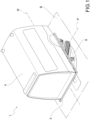
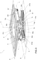
- Such a simulation device 1 is suitable for simulating movements, for example oscillations and/or vibrations, produced by a means of transport during a journey via land, air or water.
- the simulation device 1 is suitable for resting on a base plane B.
- the base plane B is horizontal.
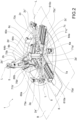
- the simulation device 1 comprises a plurality of support legs 2a, 2b, 2c, and each leg 2a; 2b; 2c of said plurality of support legs 2a, 2b, 2c extends mainly along a leg axis L between a lower end 2a'; 2b'; 2c' and an opposing upper end 2a"; 2b"; 2c".
- the simulation device 1 also comprises the universal coupler 5.
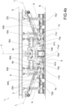
- the simulation device 1 comprises a plurality of actuators 6a, 6b, 6c, and each actuator 6a; 6b; 6c of said plurality of actuators 6a, 6b, 6c is operatively connected to a respective leg 2a; 2b; 2c of the plurality of support legs 2a, 2b, 2c.
- each actuator 6a; 6b; 6c connects to the respective leg 2a; 2b; 2c at the lower end 2a'; 2b'; 2c'.
- the simulation device 1 comprises a carriage group 7a; 7b; 7c which connects each leg 2a; 2b; 2c to the respective actuator 6a; 6b; 6c of the plurality of actuators 6a, 6b, 6c.
- the carriage group 7a; 7b; 7c is configured as a simple kinematic constraint (i.e., a carriage) which is not translatable parallel to a vertical axis V.
- the plurality of support legs 2a, 2b, 2c is oriented so that the leg axis L of each leg 2a; 2b; 2c converges toward the base plane B. In other words, the leg axes L of the support legs 2a, 2b, 2c converge towards the base plane B.
- the simulation device 1 comprises a simulation platform 3 operatively connected to the plurality of support legs 2a, 2b, 2c.
- the simulation platform 3 connects to the plurality of support legs 2a, 2b, 2c at the upper end 2a"; 2b"; 2c" of each leg 2a; 2b; 2c.
- the simulation platform 3 defines a simulation plane S configured for the installation of a structure 4 suitable for replicating the means of transport. Therefore, the plurality of support legs 2a, 2b, 2c is oriented so that the leg axis L of each leg 2a; 2b; 2c converges towards the base plane B and therefore diverges towards the simulation plane S. In other words, the leg axes L of the support legs 2a, 2b, 2c converge towards the base plane B and diverge towards the simulation plane S.
- the simulation platform 3 has a radial footprint such that the plurality of support legs 2a, 2b, 2c does not protrude beyond the peripheral edge of the simulation platform 3. In other words, the support legs are entirely positioned below the simulation platform 3.
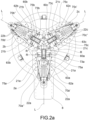
- the plurality of support legs 2a, 2b, 2c exactly consists of three angularly equally spaced legs.
- each leg axis L of each leg 2a; 2b; 2c converges toward a point of origin O.
- This point of origin O lies on the base plane B; alternatively, the point of origin O is spaced apart from the base plane B, i.e., it does not lie on said base plane B.
- the point of origin O lies on the vertical axis V orthogonal to the base plane B.
- the simulation device 1 has radial symmetry in relation to the vertical axis V of the third order.
- "Radial symmetry of the third order” means that, by projecting each leg 2a; 2b; 2c onto the base plane B, the three legs are arranged according to the vertices of an equilateral triangle, wherein the point of origin O is configured as the center of radial symmetry. Therefore, the projection of each leg portion 2a; 2b; 2c on the base plane B has a radial development that moves away from the vertical axis V.
- the universal coupler 5 connecting the simulation platform 3 to the upper end 2a"; 2b"; 2c" of each leg 2a; 2b; 2c is a universal joint.
- the universal coupler 5 is a ball joint.
- a lower fork 21a; 21b; 21c is formed at the lower end 2a'; 2b'; 2c' of each leg 2a; 2b; 2c. Furthermore, the lower fork 21a; 21b; 21c of each leg 2a; 2b; 2c is operatively connected to the respective carriage group 7a; 7b; 7c. Analogously, an upper fork 22a; 22b; 22c operatively connected to the respective universal coupler 5, is obtained at the upper end 2a"; 2b"; 2c" of each leg 2a; 2b; 2c.
- each carriage group 7a; 7b; 7c comprises at least one rail 70a'; 70a"; 70b'; 70b"; 70c'; 70c".
- each carriage group 7a; 7b; 7c comprises a pair of rails 70a', 70a"; 70b', 70b"; 70c', 70c".
- This at least one rail 70a'; 70a"; 70b'; 70b"; 70c'; 70c” allows the radial translation of the lower end 2a'; 2b'; 2c' of the respective leg 2a; 2b; 2c.
- the carriage group 7a; 7b; 7c comprises at least one tapered roller bearing 71a'; 71a"; 71b'; 71b"; 71c'; 71c".
- Such at least one tapered roller bearing 71a'; 71a"; 71b'; 71b"; 71c'; 71c" allows the lower end 2a'; 2b'; 2c' of the respective leg 2a; 2b; 2c to rotate about a rotation axis R.
- each leg 2a; 2b; 2c is orthogonal to the lower fork 21a; 21b; 21c.
- each leg 2a; 2b; 2c is constrained to the respective carriage group 7a; 7b; 7c, and therefore each carriage group 7a; 7b; 7c allows the respective leg 2a; 2b; 2c to translate along the rail 70a'; 70a"; 70b'; 70b"; 70c'; 70c" and to rotate with respect to the rotation axis R.
- the simulation device 1 has three Degrees of Freedom (DoF) and allows pitching and rolling movements; moreover, the simulation device 1 may also vary its height, measured along the vertical axis V with respect to the base plane B.
- DoF Degrees of Freedom
- the pitching movement occurs about a pitching axis P
- the rolling movement occurs about a rolling axis R' ( Fig. 1 ).
- each carriage group 7a; 7b; 7c comprises a pair of tapered roller bearings 71a', 71a"; 71b', 71b"; 71c', 71c".
- the at least one tapered roller bearing 71a'; 71a"; 71b'; 71b"; 71c'; 71c" of each carriage group 7a; 7b; 7c is a pair of tapered roller bearings 71a', 71a"; 71b', 71b”; 71c', 71c".
- each carriage group 7a; 7b; 7c also comprises a crosspiece 73a; 73b; 73c, which connects the pair of tapered roller bearings 71a', 71a"; 71b', 71b"; 71c', 71c" and is oriented parallel to the rotation axis R.
- each carriage group 7a; 7b; 7c comprises a pair of blocks 75a; 75b; 75c, and in each block of said pair of blocks 75a; 75b; 75c a seat is obtained where a respective tapered roller bearing of the pair of tapered roller bearings 71a', 71a"; 71b', 71b"; 71c', 71c" is accommodated.
- the two blocks of the pair of blocks 75a; 75b; 75c are connected to one another by the crosspiece 73a; 73b; 73c and translate on the respective pair of rails 70a', 70a"; 70b', 70b"; 70c', 70c".
- the motion return means 61a; 61b; 61c comprise a box-shaped casing 64a; 64b; 64c oriented mainly along a direction parallel to the vertical axis V ( Fig. 2 ).
- the belt that connects the motor 60a; 60b; 60c to the worm screw is accommodated in the aforementioned box-shaped casing 64a; 64b; 64c.
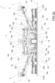
- the simulation device 1 comprises resilient means 9 for connecting the support frame 8 to the simulation platform 3 and therefore reducing the load borne by the plurality of actuators 6a, 6b, 6c.
- the resilient means 9 are coil springs.
- the simulation device 1 comprises at least three coil springs; even more preferably, six or nine coil springs.
- the simulation platform 3 when arranged parallel to the base plane B, may reach a minimum height-measured along the vertical axis V-of between 50 and 75 cm.
- the simulation platform 3-arranged parallel to the base plane B- may be positioned at a height of between 50 and 150 cm; even more preferably, between 75 and 120 cm. Therefore, the simulation device 1 may be arranged at a height, measured with respect to the base plane, which is comparable to that of a pneumatic tire.
- the height of the simulation platform 3 is comparable to the height of the chassis of the means of transport; therefore, the simulation device 1 is extremely realistic and, for example, may be used to train the personnel in loading/unloading a stretcher.
- the simulation device 1 also comprises a processing and control unit.
- This processing and control unit may:
- the processing and control unit After calculating, estimating and/or receiving as input the plurality of accelerations experienced by the means of transport while traveling, the processing and control unit converts these accelerations into actuation instructions with which it commands the movement of each actuator 6a; 6b; 6c.
- the actuation of the plurality of actuators 6a, 6b, 6c determines the movement of each leg 2a; 2b; 2c, so that the structure 4 undergoes the accelerations-calculated, estimated and/or received as input-and therefore reproduces the motion of the means of transport.
- the accelerations experienced by a means of transport during a journey are first obtained; subsequently, these accelerations are converted into actuation instructions for controlling the plurality of actuators 6a, 6b, 6c in order to reproduce the same motion of the means of transport on the structure 4.
- the plurality of accelerations reproduced with the simulation device 1 allows for training the personnel on board the structure 4, as the body of each human being on the structure 4 may perceive the same vestibular sensations, i.e., the same accelerations, that he would experience during a journey on the means of transport.
- the processing and control unit is configured to obtain the plurality of accelerations experienced by the means of transport during a journey via land, air or water. This plurality of accelerations is received as input or calculated and/or estimated.
- the processing and control unit is also configured to convert the plurality of accelerations into actuation instructions and to control the movement of each actuator 6a; 6b; 6c by means of these instructions.
- the movement of the plurality of actuators 6a, 6b, 6c causes the movement of each leg 2a; 2b; 2c so as to allow the simulation device 1 to reproduce the plurality of accelerations and thus simulate the travel of the means of transport.
- the simulation device of the present invention fully achieves the intended object thereof.
- the simulation platform moves and transfers motion to the structure (for example the cabin of an ambulance, aircraft or watercraft).
- the operators inside the structure may experience-in a protected context-the movements (e.g., oscillations, vibrations, jolts, etc.) that they would have to endure during a journey by land, air or water.
- the leg axis of each leg converges towards the base plane and diverges towards the simulation plane; therefore, the support legs are entirely positioned below the simulation platform.
- the radial dimensions of the simulation device are defined by the geometry of the platform and not by the radial dimensions of the support legs.
- the motion of each actuator is independent from that of the other actuators, and therefore it is possible to adjust the movement of the simulation device through pitching, rolling and height variation movements.
- the tapered roller bearing makes it possible to correct any misalignments that occur during the operation of the simulation device due to the load of the structure applied to the simulation platform.
- the resilient means lighten the stresses borne by the plurality of actuators. Therefore, in the presence of the resilient means, it is possible to reduce the dimensions of the plurality of actuators.
- the presence of the resilient means may increase the maximum load that may be supported by the simulation device.
- the presence of the resilient means may further reduce the minimum height achievable by the simulation platform.
- the simulation device may support a maximum load of about 3000 kilograms, preferably 2000 kilograms.
- the simulation device that is the subject of the present invention has a lower weight than similar devices designed in accordance with the prior art.
- the simulation device is cost-effective, as it requires lower production costs than similar devices currently on the market.
Landscapes
- Engineering & Computer Science (AREA)
- Theoretical Computer Science (AREA)
- Aviation & Aerospace Engineering (AREA)
- Business, Economics & Management (AREA)
- Physics & Mathematics (AREA)
- Educational Administration (AREA)
- Educational Technology (AREA)
- General Physics & Mathematics (AREA)
- Accommodation For Nursing Or Treatment Tables (AREA)
Applications Claiming Priority (1)
| Application Number | Priority Date | Filing Date | Title |
|---|---|---|---|
| IT202300022281 | 2023-10-24 |
Publications (1)
| Publication Number | Publication Date |
|---|---|
| EP4546308A1 true EP4546308A1 (de) | 2025-04-30 |
Family
ID=89427385
Family Applications (1)
| Application Number | Title | Priority Date | Filing Date |
|---|---|---|---|
| EP24207819.4A Pending EP4546308A1 (de) | 2023-10-24 | 2024-10-21 | Simulationsvorrichtung |
Country Status (1)
| Country | Link |
|---|---|
| EP (1) | EP4546308A1 (de) |
Citations (9)
| Publication number | Priority date | Publication date | Assignee | Title |
|---|---|---|---|---|
| US20050277092A1 (en) | 2004-06-01 | 2005-12-15 | Thong-Shing Hwang | Motion platform device for spatial disorientation simulation |
| WO2010068089A1 (en) | 2008-12-09 | 2010-06-17 | Trc Development B.V. | A motion platform and a simulator |
| JP2011021681A (ja) | 2009-07-15 | 2011-02-03 | Hosei Univ | 自由運動シミュレータ装置 |
| KR101656936B1 (ko) | 2014-08-25 | 2016-09-12 | 한국교통대학교산학협력단 | 앰블런스 시뮬레이터 구동을 위한 6축 액추에이터 제어를 위한 프로토콜 |
| US20170314727A1 (en) * | 2014-06-10 | 2017-11-02 | Oceaneering International, Inc. | Compensated Motion Base |
| WO2020091108A1 (ko) * | 2018-10-30 | 2020-05-07 | 한국로봇융합연구원 | 하중보상 메커니즘을 적용한 모션플랫폼 |
| WO2022136225A1 (en) * | 2020-12-24 | 2022-06-30 | Ansible Motion Limited | Motion platform apparatus and method of supporting a payload platform |
| US20220273100A1 (en) | 2019-10-25 | 2022-09-01 | Wizapply Co.,Ltd | Seat-type rocking device |
| KR20230071886A (ko) * | 2021-11-16 | 2023-05-24 | 한국생산기술연구원 | 5-자유도 시뮬레이터 |
-
2024
- 2024-10-21 EP EP24207819.4A patent/EP4546308A1/de active Pending
Patent Citations (9)
| Publication number | Priority date | Publication date | Assignee | Title |
|---|---|---|---|---|
| US20050277092A1 (en) | 2004-06-01 | 2005-12-15 | Thong-Shing Hwang | Motion platform device for spatial disorientation simulation |
| WO2010068089A1 (en) | 2008-12-09 | 2010-06-17 | Trc Development B.V. | A motion platform and a simulator |
| JP2011021681A (ja) | 2009-07-15 | 2011-02-03 | Hosei Univ | 自由運動シミュレータ装置 |
| US20170314727A1 (en) * | 2014-06-10 | 2017-11-02 | Oceaneering International, Inc. | Compensated Motion Base |
| KR101656936B1 (ko) | 2014-08-25 | 2016-09-12 | 한국교통대학교산학협력단 | 앰블런스 시뮬레이터 구동을 위한 6축 액추에이터 제어를 위한 프로토콜 |
| WO2020091108A1 (ko) * | 2018-10-30 | 2020-05-07 | 한국로봇융합연구원 | 하중보상 메커니즘을 적용한 모션플랫폼 |
| US20220273100A1 (en) | 2019-10-25 | 2022-09-01 | Wizapply Co.,Ltd | Seat-type rocking device |
| WO2022136225A1 (en) * | 2020-12-24 | 2022-06-30 | Ansible Motion Limited | Motion platform apparatus and method of supporting a payload platform |
| KR20230071886A (ko) * | 2021-11-16 | 2023-05-24 | 한국생산기술연구원 | 5-자유도 시뮬레이터 |
Similar Documents
| Publication | Publication Date | Title |
|---|---|---|
| US9757658B1 (en) | Fairground ride | |
| US9466223B2 (en) | Mobile platform | |
| JP7691741B2 (ja) | 運動発生器 | |
| KR101804415B1 (ko) | 모션 제어 장치 | |
| KR20150092125A (ko) | 비행 극장 | |
| CN107708641A (zh) | 坐式步行康复机器人 | |
| US20170225736A1 (en) | Self-Balancing Load Bearing Vehicle | |
| US9289693B1 (en) | Motion platform for a simulation device | |
| EP3278323B1 (de) | Bewegungsanordnung | |
| EP4546308A1 (de) | Simulationsvorrichtung | |
| KR20220016872A (ko) | 모션 시스템 | |
| KR20220002433A (ko) | 모션 시스템 | |
| LT6831B (lt) | Transporto priemonė su transformuojama kėde | |
| CN105005321A (zh) | 跳楼机及其动感乘骑运动系统 | |
| KR20150073820A (ko) | 슬라이드 방식의 승강장 발판장치 | |
| ES2988353T3 (es) | Sistemas de control de resistencia y métodos para atracciones de entretenimiento | |
| JP2021128196A (ja) | ヘリコプター操縦訓練システム | |
| CA2789287A1 (en) | Training device for rugby players | |
| Petzäll | Traversing step obstacles with manual wheelchairs | |
| WO2016085507A1 (en) | Motion platform for a simulation device | |
| KR102705186B1 (ko) | 중력모의 사출좌석 시스템 | |
| Crichlow | Development of a comprehensive mathematical model and physical interface for manual wheelchair simulation | |
| Kamper et al. | A low-cost, portable system for the assessment of the postural response of wheelchair users to perturbations | |
| CN115171458A (zh) | 一种直升机应急救援模拟器 | |
| RU106421U1 (ru) | Динамическая платформа тренажерного комплекса |
Legal Events
| Date | Code | Title | Description |
|---|---|---|---|
| PUAI | Public reference made under article 153(3) epc to a published international application that has entered the european phase |
Free format text: ORIGINAL CODE: 0009012 |
|
| STAA | Information on the status of an ep patent application or granted ep patent |
Free format text: STATUS: THE APPLICATION HAS BEEN PUBLISHED |
|
| AK | Designated contracting states |
Kind code of ref document: A1 Designated state(s): AL AT BE BG CH CY CZ DE DK EE ES FI FR GB GR HR HU IE IS IT LI LT LU LV MC ME MK MT NL NO PL PT RO RS SE SI SK SM TR |
|
| STAA | Information on the status of an ep patent application or granted ep patent |
Free format text: STATUS: REQUEST FOR EXAMINATION WAS MADE |
|
| 17P | Request for examination filed |
Effective date: 20251029 |