EP4546580A2 - Dreiphasige schaltanlage mit einphasiger ausrüstung in einem gehäuse - Google Patents
Dreiphasige schaltanlage mit einphasiger ausrüstung in einem gehäuse Download PDFInfo
- Publication number
- EP4546580A2 EP4546580A2 EP25164122.1A EP25164122A EP4546580A2 EP 4546580 A2 EP4546580 A2 EP 4546580A2 EP 25164122 A EP25164122 A EP 25164122A EP 4546580 A2 EP4546580 A2 EP 4546580A2
- Authority
- EP
- European Patent Office
- Prior art keywords
- phase
- compartment
- switchgear
- control gear
- circuit breaker
- Prior art date
- Legal status (The legal status is an assumption and is not a legal conclusion. Google has not performed a legal analysis and makes no representation as to the accuracy of the status listed.)
- Pending
Links
Images

Classifications
-
- H—ELECTRICITY
- H02—GENERATION; CONVERSION OR DISTRIBUTION OF ELECTRIC POWER
- H02B—BOARDS, SUBSTATIONS OR SWITCHING ARRANGEMENTS FOR THE SUPPLY OR DISTRIBUTION OF ELECTRIC POWER
- H02B13/00—Arrangement of switchgear in which switches are enclosed in, or structurally associated with, a casing, e.g. cubicle
- H02B13/02—Arrangement of switchgear in which switches are enclosed in, or structurally associated with, a casing, e.g. cubicle with metal casing
- H02B13/035—Gas-insulated switchgear
- H02B13/0352—Gas-insulated switchgear for three phase switchgear
-
- H—ELECTRICITY
- H02—GENERATION; CONVERSION OR DISTRIBUTION OF ELECTRIC POWER
- H02B—BOARDS, SUBSTATIONS OR SWITCHING ARRANGEMENTS FOR THE SUPPLY OR DISTRIBUTION OF ELECTRIC POWER
- H02B13/00—Arrangement of switchgear in which switches are enclosed in, or structurally associated with, a casing, e.g. cubicle
- H02B13/02—Arrangement of switchgear in which switches are enclosed in, or structurally associated with, a casing, e.g. cubicle with metal casing
- H02B13/025—Safety arrangements, e.g. in case of excessive pressure or fire due to electrical defect
-
- H—ELECTRICITY
- H02—GENERATION; CONVERSION OR DISTRIBUTION OF ELECTRIC POWER
- H02B—BOARDS, SUBSTATIONS OR SWITCHING ARRANGEMENTS FOR THE SUPPLY OR DISTRIBUTION OF ELECTRIC POWER
- H02B1/00—Frameworks, boards, panels, desks, casings; Details of substations or switching arrangements
- H02B1/26—Casings; Parts thereof or accessories therefor
- H02B1/30—Cabinet-type casings; Parts thereof or accessories therefor
- H02B1/32—Mounting of devices therein
-
- H—ELECTRICITY
- H02—GENERATION; CONVERSION OR DISTRIBUTION OF ELECTRIC POWER
- H02B—BOARDS, SUBSTATIONS OR SWITCHING ARRANGEMENTS FOR THE SUPPLY OR DISTRIBUTION OF ELECTRIC POWER
- H02B13/00—Arrangement of switchgear in which switches are enclosed in, or structurally associated with, a casing, e.g. cubicle
- H02B13/02—Arrangement of switchgear in which switches are enclosed in, or structurally associated with, a casing, e.g. cubicle with metal casing
-
- H—ELECTRICITY
- H02—GENERATION; CONVERSION OR DISTRIBUTION OF ELECTRIC POWER
- H02B—BOARDS, SUBSTATIONS OR SWITCHING ARRANGEMENTS FOR THE SUPPLY OR DISTRIBUTION OF ELECTRIC POWER
- H02B13/00—Arrangement of switchgear in which switches are enclosed in, or structurally associated with, a casing, e.g. cubicle
- H02B13/02—Arrangement of switchgear in which switches are enclosed in, or structurally associated with, a casing, e.g. cubicle with metal casing
- H02B13/035—Gas-insulated switchgear
- H02B13/0358—Connections to in or out conductors
Definitions
- the present invention relates to a three phase switchgear or control gear for low voltage, medium voltage or high voltage use with a substation.
- switchgear and control gear also called controlgear
- the primary circuits of the three phases are arranged in groups for each feeder circuit, together forming a three phase feeder circuit.
- This arrangement can be problematic for handling and maintenance purposes, and has associated risks of internal arc faults in the complete power circuit.
- a three phase switchgear or control gear comprising:
- the plurality of components for the first phase the second phase and the third phase each comprise a main busbar, a three position linear or rotational movement disconnector switch, a single phase circuit breaker pole, and a cable connection.
- the plurality of components for the first phase the second phase and the third phase are housed in the at least one compartment.
- the at least one compartment comprises at least two compartments.
- the main busbar, the three position linear or rotational movement disconnector switch, and the single phase circuit breaker pole are housed in a first compartment of the at least two compartments.
- the three cable connections are housed in a second compartment of the at least two compartments.
- the second compartment comprises a door or removable wall section.
- the switchgear or control gear is configured such that an operator can gain access to the inside of the second compartment via the door or removable wall section whilst the switchgear or control gear is in operation.
- the second compartment is separated from the first compartment by an arc proof segregation.
- sets of bushings are used to connect the cable connections for each phase to components for each phase housed in the first compartment.
- current and voltage sensors are embedded into each of the three sets of bushings.
- the plurality of components for the first phase the second phase and the third phase each comprises a circuit breaker single phase actuator.
- the three circuit breaker single phase actuators are housed in a compartment other than the first compartment.
- the at least one compartment comprises a third compartment.
- the three circuit breaker single phase actuators are housed in the third compartment.
- the compartment within which the three circuit breaker single phase actuators are housed comprises a door or removable wall section.
- the switchgear or control gear is configured such that an operator can gain access to the inside of the third compartment via the door or removable wall section whilst the switchgear or control gear is in operation.
- the compartment within which the three circuit breaker single phase actuators are housed is separated from the first compartment by an arc proof segregation.
- current and voltage sensors are embedded in each of the three single phase circuit breaker poles.
- Figs. 1-2 show examples of a switchgear or control gear for operation in a low voltage, medium voltage or high voltage substation.
- One example relates to a three phase switchgear or control gear that comprises at least one compartment 3, 9, 10, 12, a plurality of components for a first phase, a plurality of components for a second phase, and a plurality of components for a third phase.
- the plurality of components for the first phase the second phase and the third phase each comprise a main busbar 8, a three position linear or rotational movement disconnector switch 2, a single phase circuit breaker pole 4, and a cable connection 7.
- the plurality of components for the first phase the second phase and the third phase are housed in the at least one compartment.
- the at least one compartment comprises at least two compartments.
- the main busbar, the three position linear or rotational movement disconnector switch, and the single phase circuit breaker pole are housed in a first compartment 9 of the at least two compartments.
- the three cable connections are housed in a second compartment 10 of the at least two compartments.
- the second compartment comprises a door or removable wall section.
- the switchgear or control gear is configured such that an operator can gain access to the inside of the second compartment via the door or removable wall section whilst the switchgear or control gear is in operation.
- the second compartment is separated from the first compartment by an arc proof segregation.
- sets of bushings 5 are used to connect the cable connections for each phase to components for each phase housed in the first compartment.
- current and voltage sensors are embedded into each of the three sets of bushings.
- the plurality of components for the first phase the second phase and the third phase each comprises a circuit breaker single phase actuator 1.
- the three circuit breaker single phase actuators are housed in a compartment other than the first compartment.
- the at least one compartment comprises a third compartment 12.
- the three circuit breaker single phase actuators are housed in the third compartment.
- the compartment within which the three circuit breaker single phase actuators are housed comprises a door or removable wall section.
- the switchgear or control gear is configured such that an operator can gain access to the inside of the third compartment via the door or removable wall section whilst the switchgear or control gear is in operation.
- the compartment within which the three circuit breaker single phase actuators are housed is separated from the first compartment by an arc proof segregation 11.
- current and voltage sensors are embedded in each of the three single phase circuit breaker poles.
- the new design is applicable to both human operated switchgear and control gear as well as the switchgear or control gear with unmanned operation and maintenance.
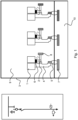
- Fig. 1 shows a detailed example of a three phase switchgear or control gear, where for ease of reference the following features shown are listed:
- the new switchgear or control gear arrangement of phase by phase opens space for redesign of the main switching devices, that can be modularized to a single phase switching device plus drive subassemblies. This can be better handled by human or automation maintenance systems (lower weight and dimensions compared to today three phase devices).
- FIG. 1 A three position disconnector switch is shown in Fig. 1 , however it withdrawal breaker operating principle is a viable alternative option.
- the feeder circuit in each phase has a short T-off from the main busbar, a three position disconnector switch, a circuit breaker and cable connection bars. While the main busbars and switching devices can be located in one big compartment common for all feeders, the cable connections are located in a cable termination box that is separate for each feeder. This facilitates access to the cable terminations for human operators, while the switchgear or control gear is in operation.
- the cable compartment segregation from the main circuit space provides a minimum IP1X degree of protection for the operator.
- Each segregated cable compartment is equipped with flaps for exhaust of the hot gases in case of internal arc or a quick acting active arc fault protection can be used for avoiding pressurizing of the cable compartments.
- Each cable compartment enclosures can then be arc proof towards the main circuit's main space as well as towards outer space.
- the current and voltage measurement is provided preferably by current and voltage sensors, that can be embedded in bushings segregating the main circuit space from the cable compartment.
- current and voltage measurement is provided via current and voltage sensors embedded in bushings.
- the current and voltage measurement can be provided by current and voltage transformers.
- the Fig.1 is showing the main circuit's compartment common for all three phases. Providing earthed metallic or insulating material segregation between phases further increases the protection against internal arc between phases.
- Fig.1 show the cable compartment box 10 embedding all three phases for each feeder.
- the cable compartment can be further segregated per phase to increase protection against internal arc between phases.
- Fig.1 shows the cable compartment that is arc proof separated from the main circuit space. However, the cable compartment does not have to be separated from the main circuit space.
- rotational three position disconnector switches shown in Fig.1 can be replaced with a linear three position disconnector switches.
- the withdrawable operating principle can be applied, i.e. instead of having a disconnector switch device the circuit breaker pole can be designed as withdrawable and the movement of the pole does the disconnecting.
- the current and voltage sensors are shown embedded in the bushings. However, these components can be designed as stand alone as well, and positioned in the cable compartment or in the main circuits compartment. Also, the current and voltage sensors can be embedded in a circuit breaker pole.
- Fig.1 shows a switchgear or control gear with unmanned operation, with primary circuits in the main circuits' space accessible for human operator only when deenergized.
- a safe space 12 is provided as an additional compartment within which the circuit breaker single phase actuators and auxiliaries are housed, with this safe space 12 segregated from the main compartment by an additional arc proof segregation 11.
- additional arc proof segregation 11 covering the main circuits' compartment for maintenance and operation personnel.
- the bottom wall of the cable termination compartment shown at the bottom of Fig. 2 , can be a removable cover or doors enabling access by human operator.
- the primary circuit can include other components and devices not described in Fig.1 , such as earthing switch, voltage indication, surge arrestors, UFES, IS-limitors, contactors, load-break switches, fuses.
- earthing switch voltage indication
- surge arrestors UFES
- IS-limitors contactors
- load-break switches fuses.
- the switchgear or control gear outer envelope does not have to be arc proof if the switchgear or control gear is located in a substation denying human access when the switchgear or controlgear is in operation.
Landscapes
- Engineering & Computer Science (AREA)
- Power Engineering (AREA)
- Patch Boards (AREA)
- Gas-Insulated Switchgears (AREA)
Priority Applications (1)
| Application Number | Priority Date | Filing Date | Title |
|---|---|---|---|
| EP25164122.1A EP4546580A3 (de) | 2018-12-19 | 2018-12-19 | Dreiphasige schaltanlage mit einphasiger ausrüstung in einem gehäuse |
Applications Claiming Priority (2)
| Application Number | Priority Date | Filing Date | Title |
|---|---|---|---|
| EP18214153.1A EP3671989B1 (de) | 2018-12-19 | 2018-12-19 | Dreiphasen-schaltanlage mit einphasiger ausrüstung in einem gehäuse |
| EP25164122.1A EP4546580A3 (de) | 2018-12-19 | 2018-12-19 | Dreiphasige schaltanlage mit einphasiger ausrüstung in einem gehäuse |
Related Parent Applications (2)
| Application Number | Title | Priority Date | Filing Date |
|---|---|---|---|
| EP18214153.1A Division EP3671989B1 (de) | 2018-12-19 | 2018-12-19 | Dreiphasen-schaltanlage mit einphasiger ausrüstung in einem gehäuse |
| EP18214153.1A Division-Into EP3671989B1 (de) | 2018-12-19 | 2018-12-19 | Dreiphasen-schaltanlage mit einphasiger ausrüstung in einem gehäuse |
Publications (2)
| Publication Number | Publication Date |
|---|---|
| EP4546580A2 true EP4546580A2 (de) | 2025-04-30 |
| EP4546580A3 EP4546580A3 (de) | 2025-07-02 |
Family
ID=64746231
Family Applications (2)
| Application Number | Title | Priority Date | Filing Date |
|---|---|---|---|
| EP25164122.1A Pending EP4546580A3 (de) | 2018-12-19 | 2018-12-19 | Dreiphasige schaltanlage mit einphasiger ausrüstung in einem gehäuse |
| EP18214153.1A Active EP3671989B1 (de) | 2018-12-19 | 2018-12-19 | Dreiphasen-schaltanlage mit einphasiger ausrüstung in einem gehäuse |
Family Applications After (1)
| Application Number | Title | Priority Date | Filing Date |
|---|---|---|---|
| EP18214153.1A Active EP3671989B1 (de) | 2018-12-19 | 2018-12-19 | Dreiphasen-schaltanlage mit einphasiger ausrüstung in einem gehäuse |
Country Status (4)
| Country | Link |
|---|---|
| US (1) | US11637414B2 (de) |
| EP (2) | EP4546580A3 (de) |
| CN (1) | CN113196602B (de) |
| WO (1) | WO2020126749A1 (de) |
Families Citing this family (5)
| Publication number | Priority date | Publication date | Assignee | Title |
|---|---|---|---|---|
| EP3671986B1 (de) * | 2018-12-19 | 2025-05-14 | ABB Schweiz AG | Schaltanlage |
| EP3671991B1 (de) * | 2018-12-19 | 2025-04-23 | ABB Schweiz AG | Dreiphasige schaltanlage |
| EP4546580A3 (de) * | 2018-12-19 | 2025-07-02 | Abb Schweiz Ag | Dreiphasige schaltanlage mit einphasiger ausrüstung in einem gehäuse |
| EP3754681B1 (de) | 2019-06-21 | 2026-01-21 | ABB Schweiz AG | Trennschalter mit drei positionen |
| EP3836322B1 (de) | 2019-12-11 | 2023-08-30 | ABB Schweiz AG | Schutzschalterpol für niederspannungs- oder mittelspannungsbetrieb |
Family Cites Families (42)
| Publication number | Priority date | Publication date | Assignee | Title |
|---|---|---|---|---|
| US4528614A (en) * | 1983-10-07 | 1985-07-09 | Westinghouse Electric Corp. | Electric control center having integral air-ventilation system |
| US5585611A (en) * | 1994-03-31 | 1996-12-17 | Abb Power T&D Company Inc. | Interrupter assembly |
| DE4412784C2 (de) * | 1994-04-18 | 1997-04-03 | Abb Patent Gmbh | Strom- und Spannungssensor für ein Hochspannungsschaltfeld |
| DE29501082U1 (de) * | 1995-01-13 | 1995-03-23 | Siemens AG, 80333 München | Anordnung zur Spannungsmessung an feststoffisolierter Sammelschiene von Mittelspannungs-Schaltanlagen |
| SE9601217D0 (sv) * | 1996-03-29 | 1996-03-29 | Asea Brown Boveri | Skjutbar dörr för ställverk och kontrollskåp |
| JP2001352621A (ja) * | 2000-06-02 | 2001-12-21 | Mitsubishi Electric Corp | ガス絶縁開閉装置 |
| JP4329923B2 (ja) * | 2002-10-31 | 2009-09-09 | 三菱電機株式会社 | ガス絶縁スイッチギヤ |
| JP4237591B2 (ja) * | 2003-09-17 | 2009-03-11 | 株式会社日立製作所 | ガス絶縁開閉装置 |
| DE102005029600A1 (de) * | 2004-06-28 | 2006-01-19 | Abb Technology Ag | Gasisolierte Mittelspannungs-Schaltanlage |
| US20070252599A1 (en) * | 2006-05-01 | 2007-11-01 | Eaton Corporation | Circuit interrupter including manual selector selecting different point-on-wave switching characteristics |
| EP1983625A1 (de) * | 2007-04-18 | 2008-10-22 | Eaton Electric B.V. | Entfernbares Fach zur Verwendung in einer Funktionseinheit einer elektrischen Schaltanlage |
| US8743532B2 (en) * | 2009-08-25 | 2014-06-03 | Mitsubishi Electric Corporation | Switchgear |
| KR101248608B1 (ko) * | 2011-08-31 | 2013-03-28 | 현대중공업 주식회사 | 차단부 인출식 큐비클형 가스절연 개폐장치 |
| RU2496199C2 (ru) * | 2011-09-21 | 2013-10-20 | Общество с ограниченной ответственностью "ВостокЭнергоКомплект" | Высоковольтное комплектное распределительное устройство |
| EP2618356A1 (de) * | 2012-01-19 | 2013-07-24 | ABB Technology AG | Spannungs- und/oder Stromerfassungsvorrichtung für Nieder-, Mittel- oder Hochspannungsschaltvorrichtungen |
| DK2833494T3 (en) * | 2012-03-27 | 2017-05-01 | Mitsubishi Electric Corp | GAS INSULATED DISTRIBUTION PLANT |
| CN202678803U (zh) * | 2012-06-08 | 2013-01-16 | 广东邦能电气有限公司 | 大电流功能复合型高压金属封闭开关设备 |
| CN104937793B (zh) * | 2013-01-15 | 2017-04-12 | 三菱电机株式会社 | 气体绝缘开关装置 |
| CN203071483U (zh) * | 2013-02-28 | 2013-07-17 | 天安电气集团浙江电气有限公司 | 气体绝缘金属封闭开关设备 |
| CN203119378U (zh) * | 2013-04-02 | 2013-08-07 | 广东省顺德开关厂有限公司 | 一种中压绝缘金属封闭开关设备 |
| CN105229879B (zh) * | 2014-04-29 | 2018-05-29 | 三菱电机株式会社 | 气体绝缘开关设备 |
| CN104377585A (zh) * | 2014-11-28 | 2015-02-25 | 湖南长高高压开关集团股份公司 | 一种模块化智能箱型固定充气式高压交流金属封闭开关设备 |
| CN107005032A (zh) * | 2014-12-11 | 2017-08-01 | 三菱电机株式会社 | 开关装置 |
| JP6143990B1 (ja) * | 2015-12-02 | 2017-06-07 | 三菱電機株式会社 | ガス絶縁開閉装置 |
| CN105655912B (zh) * | 2016-03-11 | 2018-05-15 | 中天电气技术有限公司 | 一种环境友好型气体绝缘开关柜 |
| US10305262B2 (en) * | 2016-09-26 | 2019-05-28 | Bethel Idiculla Johnson | Medium voltage switchgear enclosure |
| US9953790B1 (en) * | 2016-10-11 | 2018-04-24 | Eaton Intelligent Power Limited | Electrical switching apparatus and sensing assembly therefor |
| WO2018222837A1 (en) * | 2017-05-31 | 2018-12-06 | Abb Schweiz Ag | Switchgear system and system for providing access to a switchgear system for inspection by an automated mechanism |
| EP3422503A1 (de) | 2017-06-28 | 2019-01-02 | ABB Schweiz AG | Ein interner roboter-manipulator für unbemannte betriebs- und wartungsarbeiten bei ausfahbarer leistungsschaltern und ein verfahren zum betreiben des roboter-manipulators |
| CN110832720B (zh) | 2017-06-28 | 2022-06-24 | Abb瑞士股份有限公司 | 包含无人操作和维护的开关装置或控制装置的变电站 |
| EP3421190B1 (de) | 2017-06-28 | 2022-05-04 | ABB Schweiz AG | Schaltgerät mit unbemannter bedienung und wartung sowie verfahren zum betrieb davon |
| CN108574224A (zh) * | 2017-12-10 | 2018-09-25 | 人民电器集团上海有限公司 | 一种户内铠装式交流金属封闭开关柜 |
| CN208045958U (zh) * | 2017-12-22 | 2018-11-02 | 上海大华电器设备有限公司 | 单箱式环保气体绝缘开关柜 |
| US10923888B2 (en) * | 2018-03-12 | 2021-02-16 | Eaton Intelligent Power Limited | Interchangeable switchgear modules and related systems |
| WO2019224974A1 (ja) * | 2018-05-24 | 2019-11-28 | 三菱電機株式会社 | ガス絶縁開閉装置 |
| EP4546580A3 (de) * | 2018-12-19 | 2025-07-02 | Abb Schweiz Ag | Dreiphasige schaltanlage mit einphasiger ausrüstung in einem gehäuse |
| EP3671991B1 (de) * | 2018-12-19 | 2025-04-23 | ABB Schweiz AG | Dreiphasige schaltanlage |
| EP3671990B1 (de) * | 2018-12-19 | 2021-11-24 | ABB Schweiz AG | Dreiphasiges schaltgerät |
| EP3671986B1 (de) * | 2018-12-19 | 2025-05-14 | ABB Schweiz AG | Schaltanlage |
| EP3671988A1 (de) * | 2018-12-19 | 2020-06-24 | ABB Schweiz AG | Hermetischgasdichte schaltanlage mit einem einzelnes fach für leistungsschalter, trennschalter mit dreipositionen und hauptbusschiene. |
| EP3671992B1 (de) * | 2018-12-19 | 2021-06-16 | ABB Schweiz AG | Schaltanlage |
| EP3836322B1 (de) * | 2019-12-11 | 2023-08-30 | ABB Schweiz AG | Schutzschalterpol für niederspannungs- oder mittelspannungsbetrieb |
-
2018
- 2018-12-19 EP EP25164122.1A patent/EP4546580A3/de active Pending
- 2018-12-19 EP EP18214153.1A patent/EP3671989B1/de active Active
-
2019
- 2019-12-11 CN CN201980084590.1A patent/CN113196602B/zh active Active
- 2019-12-11 WO PCT/EP2019/084676 patent/WO2020126749A1/en not_active Ceased
-
2021
- 2021-06-04 US US17/338,685 patent/US11637414B2/en active Active
Also Published As
| Publication number | Publication date |
|---|---|
| CN113196602B (zh) | 2023-12-29 |
| US20210313781A1 (en) | 2021-10-07 |
| EP4546580A3 (de) | 2025-07-02 |
| CN113196602A (zh) | 2021-07-30 |
| WO2020126749A1 (en) | 2020-06-25 |
| US11637414B2 (en) | 2023-04-25 |
| EP3671989A1 (de) | 2020-06-24 |
| EP3671989B1 (de) | 2025-08-13 |
Similar Documents
| Publication | Publication Date | Title |
|---|---|---|
| US11637414B2 (en) | Three phase switchgear using single phase equipment in single casing | |
| KR101058918B1 (ko) | 진공 절연 스위치기어 | |
| US8248760B2 (en) | Switch arrangement for an electrical switchgear | |
| EP2543121B1 (de) | Schaltanordnung für eine elektrische schaltanlage | |
| US9601281B2 (en) | Multiphase circuit breaker system having a short-circuit link | |
| US11682885B2 (en) | Switchgear | |
| WO2014112135A1 (ja) | ガス絶縁スイッチギヤ | |
| EP2405546B1 (de) | Elektrische Schaltanlage | |
| EP1983625A1 (de) | Entfernbares Fach zur Verwendung in einer Funktionseinheit einer elektrischen Schaltanlage | |
| CN111342384B (zh) | 三相开关装置或控制装置 | |
| US11139642B2 (en) | Switchgear or control gear | |
| CN1007769B (zh) | 具有分成封闭间隔的金属铠装配电装置 | |
| US7310220B2 (en) | High voltage outdoor substation | |
| EP3671991B1 (de) | Dreiphasige schaltanlage | |
| JP2798930B2 (ja) | ガス絶縁開閉装置 | |
| CN105305288A (zh) | 具有分成封闭间隔的金属铠装配电装置 | |
| US1756865A (en) | High-potential switching station | |
| Blower et al. | Trends in distribution transformer protection | |
| CZ11978U1 (cs) | Dvousystémová kobková rozvodna | |
| JPWO2018212210A1 (ja) | 遮断器及びスイッチギヤ |
Legal Events
| Date | Code | Title | Description |
|---|---|---|---|
| PUAI | Public reference made under article 153(3) epc to a published international application that has entered the european phase |
Free format text: ORIGINAL CODE: 0009012 |
|
| STAA | Information on the status of an ep patent application or granted ep patent |
Free format text: STATUS: THE APPLICATION HAS BEEN PUBLISHED |
|
| AC | Divisional application: reference to earlier application |
Ref document number: 3671989 Country of ref document: EP Kind code of ref document: P |
|
| AK | Designated contracting states |
Kind code of ref document: A2 Designated state(s): AL AT BE BG CH CY CZ DE DK EE ES FI FR GB GR HR HU IE IS IT LI LT LU LV MC MK MT NL NO PL PT RO RS SE SI SK SM TR |
|
| PUAL | Search report despatched |
Free format text: ORIGINAL CODE: 0009013 |
|
| AK | Designated contracting states |
Kind code of ref document: A3 Designated state(s): AL AT BE BG CH CY CZ DE DK EE ES FI FR GB GR HR HU IE IS IT LI LT LU LV MC MK MT NL NO PL PT RO RS SE SI SK SM TR |
|
| RIC1 | Information provided on ipc code assigned before grant |
Ipc: H02B 13/025 20060101ALI20250523BHEP Ipc: H02B 13/02 20060101AFI20250523BHEP |
|
| STAA | Information on the status of an ep patent application or granted ep patent |
Free format text: STATUS: REQUEST FOR EXAMINATION WAS MADE |
|
| 17P | Request for examination filed |
Effective date: 20251218 |
|
| STAA | Information on the status of an ep patent application or granted ep patent |
Free format text: STATUS: EXAMINATION IS IN PROGRESS |
|
| 17Q | First examination report despatched |
Effective date: 20260330 |