EP4548807A1 - Structure en treillis à angle droit et à haute stabilité et liberté de conception, faisant office de structure ou d'étagère - Google Patents
Structure en treillis à angle droit et à haute stabilité et liberté de conception, faisant office de structure ou d'étagère Download PDFInfo
- Publication number
- EP4548807A1 EP4548807A1 EP24196579.7A EP24196579A EP4548807A1 EP 4548807 A1 EP4548807 A1 EP 4548807A1 EP 24196579 A EP24196579 A EP 24196579A EP 4548807 A1 EP4548807 A1 EP 4548807A1
- Authority
- EP
- European Patent Office
- Prior art keywords
- struts
- truss structure
- structure according
- elements
- strut
- Prior art date
- Legal status (The legal status is an assumption and is not a legal conclusion. Google has not performed a legal analysis and makes no representation as to the accuracy of the status listed.)
- Pending
Links
Images


Classifications
-
- A—HUMAN NECESSITIES
- A47—FURNITURE; DOMESTIC ARTICLES OR APPLIANCES; COFFEE MILLS; SPICE MILLS; SUCTION CLEANERS IN GENERAL
- A47B—TABLES; DESKS; OFFICE FURNITURE; CABINETS; DRAWERS; GENERAL DETAILS OF FURNITURE
- A47B47/00—Cabinets, racks or shelf units, characterised by features related to dismountability or building-up from elements
- A47B47/04—Cabinets, racks or shelf units, characterised by features related to dismountability or building-up from elements made mainly of wood or plastics
- A47B47/05—Cabinets, racks or shelf units, characterised by features related to dismountability or building-up from elements made mainly of wood or plastics with panels on a separate frame, e.g. a metal frame
-
- A—HUMAN NECESSITIES
- A47—FURNITURE; DOMESTIC ARTICLES OR APPLIANCES; COFFEE MILLS; SPICE MILLS; SUCTION CLEANERS IN GENERAL
- A47B—TABLES; DESKS; OFFICE FURNITURE; CABINETS; DRAWERS; GENERAL DETAILS OF FURNITURE
- A47B47/00—Cabinets, racks or shelf units, characterised by features related to dismountability or building-up from elements
- A47B47/0016—Node corner connectors, e.g. cubic
-
- A—HUMAN NECESSITIES
- A47—FURNITURE; DOMESTIC ARTICLES OR APPLIANCES; COFFEE MILLS; SPICE MILLS; SUCTION CLEANERS IN GENERAL
- A47B—TABLES; DESKS; OFFICE FURNITURE; CABINETS; DRAWERS; GENERAL DETAILS OF FURNITURE
- A47B47/00—Cabinets, racks or shelf units, characterised by features related to dismountability or building-up from elements
- A47B47/02—Cabinets, racks or shelf units, characterised by features related to dismountability or building-up from elements made of metal only
-
- A—HUMAN NECESSITIES
- A47—FURNITURE; DOMESTIC ARTICLES OR APPLIANCES; COFFEE MILLS; SPICE MILLS; SUCTION CLEANERS IN GENERAL
- A47B—TABLES; DESKS; OFFICE FURNITURE; CABINETS; DRAWERS; GENERAL DETAILS OF FURNITURE
- A47B47/00—Cabinets, racks or shelf units, characterised by features related to dismountability or building-up from elements
- A47B47/02—Cabinets, racks or shelf units, characterised by features related to dismountability or building-up from elements made of metal only
- A47B47/03—Cabinets, racks or shelf units, characterised by features related to dismountability or building-up from elements made of metal only with panels separate from the frame
-
- E—FIXED CONSTRUCTIONS
- E04—BUILDING
- E04B—GENERAL BUILDING CONSTRUCTIONS; WALLS, e.g. PARTITIONS; ROOFS; FLOORS; CEILINGS; INSULATION OR OTHER PROTECTION OF BUILDINGS
- E04B1/00—Constructions in general; Structures which are not restricted either to walls, e.g. partitions, or floors or ceilings or roofs
- E04B1/38—Connections for building structures in general
- E04B1/58—Connections for building structures in general of bar-shaped building elements
- E04B1/5825—Connections for building structures in general of bar-shaped building elements with a closed cross-section
- E04B1/5831—Connections for building structures in general of bar-shaped building elements with a closed cross-section of substantially rectangular form
-
- F—MECHANICAL ENGINEERING; LIGHTING; HEATING; WEAPONS; BLASTING
- F16—ENGINEERING ELEMENTS AND UNITS; GENERAL MEASURES FOR PRODUCING AND MAINTAINING EFFECTIVE FUNCTIONING OF MACHINES OR INSTALLATIONS; THERMAL INSULATION IN GENERAL
- F16B—DEVICES FOR FASTENING OR SECURING CONSTRUCTIONAL ELEMENTS OR MACHINE PARTS TOGETHER, e.g. NAILS, BOLTS, CIRCLIPS, CLAMPS, CLIPS OR WEDGES; JOINTS OR JOINTING
- F16B12/00—Jointing of furniture or the like, e.g. hidden from exterior
- F16B12/40—Joints for furniture tubing
-
- F—MECHANICAL ENGINEERING; LIGHTING; HEATING; WEAPONS; BLASTING
- F16—ENGINEERING ELEMENTS AND UNITS; GENERAL MEASURES FOR PRODUCING AND MAINTAINING EFFECTIVE FUNCTIONING OF MACHINES OR INSTALLATIONS; THERMAL INSULATION IN GENERAL
- F16B—DEVICES FOR FASTENING OR SECURING CONSTRUCTIONAL ELEMENTS OR MACHINE PARTS TOGETHER, e.g. NAILS, BOLTS, CIRCLIPS, CLAMPS, CLIPS OR WEDGES; JOINTS OR JOINTING
- F16B12/00—Jointing of furniture or the like, e.g. hidden from exterior
- F16B12/44—Leg joints; Corner joints
-
- F—MECHANICAL ENGINEERING; LIGHTING; HEATING; WEAPONS; BLASTING
- F16—ENGINEERING ELEMENTS AND UNITS; GENERAL MEASURES FOR PRODUCING AND MAINTAINING EFFECTIVE FUNCTIONING OF MACHINES OR INSTALLATIONS; THERMAL INSULATION IN GENERAL
- F16B—DEVICES FOR FASTENING OR SECURING CONSTRUCTIONAL ELEMENTS OR MACHINE PARTS TOGETHER, e.g. NAILS, BOLTS, CIRCLIPS, CLAMPS, CLIPS OR WEDGES; JOINTS OR JOINTING
- F16B12/00—Jointing of furniture or the like, e.g. hidden from exterior
- F16B12/44—Leg joints; Corner joints
- F16B12/50—Metal corner connections
-
- F—MECHANICAL ENGINEERING; LIGHTING; HEATING; WEAPONS; BLASTING
- F16—ENGINEERING ELEMENTS AND UNITS; GENERAL MEASURES FOR PRODUCING AND MAINTAINING EFFECTIVE FUNCTIONING OF MACHINES OR INSTALLATIONS; THERMAL INSULATION IN GENERAL
- F16B—DEVICES FOR FASTENING OR SECURING CONSTRUCTIONAL ELEMENTS OR MACHINE PARTS TOGETHER, e.g. NAILS, BOLTS, CIRCLIPS, CLAMPS, CLIPS OR WEDGES; JOINTS OR JOINTING
- F16B7/00—Connections of rods or tubes, e.g. of non-circular section, mutually, including resilient connections
- F16B7/04—Clamping or clipping connections
- F16B7/044—Clamping or clipping connections for rods or tubes being in angled relationship
- F16B7/0446—Clamping or clipping connections for rods or tubes being in angled relationship for tubes using the innerside thereof
- F16B7/0453—Clamping or clipping connections for rods or tubes being in angled relationship for tubes using the innerside thereof the tubes being drawn towards each other
-
- F—MECHANICAL ENGINEERING; LIGHTING; HEATING; WEAPONS; BLASTING
- F16—ENGINEERING ELEMENTS AND UNITS; GENERAL MEASURES FOR PRODUCING AND MAINTAINING EFFECTIVE FUNCTIONING OF MACHINES OR INSTALLATIONS; THERMAL INSULATION IN GENERAL
- F16B—DEVICES FOR FASTENING OR SECURING CONSTRUCTIONAL ELEMENTS OR MACHINE PARTS TOGETHER, e.g. NAILS, BOLTS, CIRCLIPS, CLAMPS, CLIPS OR WEDGES; JOINTS OR JOINTING
- F16B7/00—Connections of rods or tubes, e.g. of non-circular section, mutually, including resilient connections
- F16B7/18—Connections of rods or tubes, e.g. of non-circular section, mutually, including resilient connections using screw-thread elements
-
- F—MECHANICAL ENGINEERING; LIGHTING; HEATING; WEAPONS; BLASTING
- F16—ENGINEERING ELEMENTS AND UNITS; GENERAL MEASURES FOR PRODUCING AND MAINTAINING EFFECTIVE FUNCTIONING OF MACHINES OR INSTALLATIONS; THERMAL INSULATION IN GENERAL
- F16S—CONSTRUCTIONAL ELEMENTS IN GENERAL; STRUCTURES BUILT-UP FROM SUCH ELEMENTS, IN GENERAL
- F16S3/00—Elongated members, e.g. profiled members; Assemblies thereof; Gratings or grilles
- F16S3/06—Assemblies of elongated members
- F16S3/08—Assemblies of elongated members forming frameworks, e.g. gratings
-
- A—HUMAN NECESSITIES
- A47—FURNITURE; DOMESTIC ARTICLES OR APPLIANCES; COFFEE MILLS; SPICE MILLS; SUCTION CLEANERS IN GENERAL
- A47B—TABLES; DESKS; OFFICE FURNITURE; CABINETS; DRAWERS; GENERAL DETAILS OF FURNITURE
- A47B2230/00—Furniture jointing; Furniture with such jointing
- A47B2230/0074—Mortise and tenon joints or the like including some general male and female connections
- A47B2230/0085—Mutually slotted furniture joints
-
- A—HUMAN NECESSITIES
- A47—FURNITURE; DOMESTIC ARTICLES OR APPLIANCES; COFFEE MILLS; SPICE MILLS; SUCTION CLEANERS IN GENERAL
- A47B—TABLES; DESKS; OFFICE FURNITURE; CABINETS; DRAWERS; GENERAL DETAILS OF FURNITURE
- A47B2230/00—Furniture jointing; Furniture with such jointing
- A47B2230/15—Joining of sectional members by means of inner tensioning rods
-
- E—FIXED CONSTRUCTIONS
- E04—BUILDING
- E04B—GENERAL BUILDING CONSTRUCTIONS; WALLS, e.g. PARTITIONS; ROOFS; FLOORS; CEILINGS; INSULATION OR OTHER PROTECTION OF BUILDINGS
- E04B1/00—Constructions in general; Structures which are not restricted either to walls, e.g. partitions, or floors or ceilings or roofs
- E04B1/38—Connections for building structures in general
- E04B1/58—Connections for building structures in general of bar-shaped building elements
- E04B1/5825—Connections for building structures in general of bar-shaped building elements with a closed cross-section
- E04B2001/5856—Connections for building structures in general of bar-shaped building elements with a closed cross-section using the innerside thereof
-
- F—MECHANICAL ENGINEERING; LIGHTING; HEATING; WEAPONS; BLASTING
- F16—ENGINEERING ELEMENTS AND UNITS; GENERAL MEASURES FOR PRODUCING AND MAINTAINING EFFECTIVE FUNCTIONING OF MACHINES OR INSTALLATIONS; THERMAL INSULATION IN GENERAL
- F16B—DEVICES FOR FASTENING OR SECURING CONSTRUCTIONAL ELEMENTS OR MACHINE PARTS TOGETHER, e.g. NAILS, BOLTS, CIRCLIPS, CLAMPS, CLIPS OR WEDGES; JOINTS OR JOINTING
- F16B12/00—Jointing of furniture or the like, e.g. hidden from exterior
- F16B12/10—Jointing of furniture or the like, e.g. hidden from exterior using pegs, bolts, tenons, clamps, clips, or the like
- F16B12/28—Jointing of furniture or the like, e.g. hidden from exterior using pegs, bolts, tenons, clamps, clips, or the like for metal furniture parts
- F16B12/30—Jointing of furniture or the like, e.g. hidden from exterior using pegs, bolts, tenons, clamps, clips, or the like for metal furniture parts using threaded bolts
Definitions
- node refers to any meeting point of at least two struts, regardless of whether their ends meet, including branches and intersections.
- USM Haller furniture featuring a metal frame made of struts with spherical connectors at the corners.
- Plug-in systems are also known (e.g. GB1322514A Varichon or utility model DE29601648U1 Gravbaum), whose struts at the corners are put together to form a spatial rectangular framework using plug-in angle pieces, T-pieces, crosses and also corner elements with one or two extensions at right angles to them and are fixed using inconspicuous cross screws.
- the utility model DE20319373U1 such a solution, wherein a node element (7) with threads is introduced into a strut, wherein screws (14) are anchored in the node element through holes in the struts and fixed with a lock nut, and then serve to fix the struts.
- the CN110030244A shows a corner connection of three struts standing at right angles to each other using clamping wedges and corner covers.
- the DE102017130758A1 (Schlehmeier) also shows a strut insert, onto which an extension is screwed through a hole and by means of an internal cross screw the strut placed over it is locked in place.
- the EP4039131A1 shows a construction method of a rectangular framework using tubular frames, which are created by cutting and bending and joined together in cross struts using bolts.
- the objective of the invention was to develop a maximally stable framework with the same or similar appearance as the competition and low costs, at least for the basic elements, and to ensure compatibility with subsequent additions and combinations using more traditionally constructed connections and struts, thus achieving a combination of stability and flexibility in the form of a mixed system.
- vertically and horizontally continuous struts are used. Their intersection nodes exhibit high, play-free angular stability and their corners and end struts are attractively designed, while at the same time allowing for the installation of further connections.
- the high angular stability is achieved by special recesses in the struts, which allow the struts to cross, forming a positive connection when the struts are clamped together by means of screw connections.
- the recesses can also be provided identically at corners and edges, where they ensure a smooth, closed external appearance that can be easily expanded.
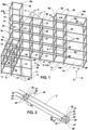
- Fig. 1 clearly shows a truss structure according to the invention
- Fig. 2 clearly shows a strut with recesses according to the invention
- Fig. 3 A to 3 C also clearly shows the joining of struts processed in this way to a reef knot
- Fig.4 several expansion options of a truss structure according to the invention in a clear exploded view
- Fig. 5 a fixed connector with braced strut in vertical section
- Fig. 6 Tension elements in a clear representation for assembling a structure including extensions
- Fig. 7 also clearly shows the all-round fitting of a strut with connectors and subsequent struts
- Fig. 1 clearly shows a truss structure according to the invention
- Fig. 2 clearly shows a strut with recesses according to the invention
- Fig. 3 A to 3 C also clearly shows the joining of struts processed in this way to a reef knot
- Fig.4 several expansion options of a truss structure according to
- FIG. 8 clearly shows the use of bent or mitred struts for any directional changes of the truss structure
- Fig. 9 A and B Horizontal sections through the necessary connectors including struts and Fig. 10 a vertical section through another bracing option with a connector.
- Fig. 1 shows a rectangular framework structure according to the invention in several forms, including supplementary elements and various height units, represented three-dimensionally. Reference numbers of parts referred to in this figure but not visible and only explained in subsequent figures are placed in parentheses. The design of the framework structure with shelves, side and rear walls, or drawer and door elements, however, is not part of this application. For easier orientation in the description, an XYZ triad is drawn.
- a truss structure consists of a combination of units 1.
- Such a unit represents an empty cuboid or cube, the edges of which are formed by struts 2, which are connected to each other at the corners in so-called nodes 3.
- struts 2 which are connected to each other at the corners in so-called nodes 3.
- nodes 3 By imaginarily stacking or arranging these units 1 one on top of the other, a rectangular truss structure of any size is created. Even if the width, depth, and height of a unit 1 can be freely selected, application-oriented dimensions are recommended, analogous to the so-called "file heights" of cabinets. With identical dimensions, a cubic structure is created, which offers the advantage that the design accessories can be inserted in all directions and orientations.
- the vertical struts 11 are slightly extended downwards to accommodate a standard threaded plug with a screwed-in adjusting slider 8.
- each structure can be implemented individually, or one can work with inexpensively manufactured, frequently required basic elements, which are included in almost every plan, such as elements with two to six or seven stacked units 1, and then expand these using add-on elements or link them together to form the planned structure, as is common with shelving systems.
- the individual implementation is much more stable to construct, as it offers the possibility of using a particularly large number of continuous struts and connecting them in an angularly stable manner using the recesses (21) according to the invention in cross nodes 31 and at the edges with corner nodes 32 and end nodes 33.
- lattices are usually created from intersecting struts, which are then clamped together using spacer struts 13 and tension elements (6), or connecting struts 14 and connectors 41, 41b.
- the framework shown contains such a cube structure and can be viewed as a combination of grids of different sizes.
- a largely free-standing grid 5a can be seen in the X-Y plane, intended as a partition wall for customers, three units 1 wide and two units high. Adjacent to this in the depth direction -Z are three structural elements of equal height, each with two units 1, which can be designed as a sales counter, for example.
- Two grids 5b can be seen in the X-Y direction, each with two units in the Y direction. Adjacent to this around the corner in the X direction are three more structural elements, which are four units 1 high and can be equipped with goods for presentation. They are created from two grids 5c with three units in the X direction and four units in the Y direction.
- This existing truss structure will later be expanded to include a structural element designed as a wardrobe 9 with storage options.
- This element consists of three grids 5d in an X-Z orientation, five units high, and units 1 and 1a of different widths, and thus spacer struts 13, 13a of different lengths, and matching tension elements (6) running in the X-direction. While the designated screws 36 are used on the right-hand side and inside, on the left-hand side the tension elements are directly screwed to connectors 41b, which have a matching thread (49). The connectors 41 are screwed into the existing structure at the corner and end nodes 32, 33. The two units can now be plugged and clamped together using the connecting struts 14, forming another usable element.
- the front horizontal strut 13b can also be designed with a larger oval cross-section and hard chrome-plated surface as known as a clothes rail, and a shoe rack can be suspended in the lowest horizontal frame position.
- the existing truss structure could also be extended by just one element, whereby only one grid 5d with only four units is screwed directly into the screw threads (49) of the connectors 41b by means of longer screws 36a and attached to the existing structure with connecting struts 14 and connectors 41.
- the wardrobe 9 is here one unit higher than the adjacent structure, which is now to be raised by another unit.
- connectors 41 are attached to the upper nodes 3 in the Y direction and connecting struts 14 are pushed on.
- the closure is achieved by a small grid 5e as a frame in the XZ direction, whose nodes 32 are also screwed directly into the screw thread (49) of the connectors 41b at the corners with longer screws 36a. This arrangement is then pushed and clamped into the connecting struts 14 attached with connectors 41.
- reef nodes 31 generate an extremely high level of stability that a classic modular system cannot match.
- Reef nodes 31 also include nodes at corners and edges, provided they have the recesses 21 according to the invention, such as the corner nodes 32 and end nodes 33 in Fig. 4 .
- Fig. 2 shows these recesses 21 in a strut 2, which provide this stability and also allow for axially precise expansion using connectors (41).
- a recess 21 consists of two similar incisions 22 with a fillet 23, which are only slightly wider than the wall thickness of the crossing strut (not shown), and whose center distance is equal to the center distance of the side walls of the crossing strut, and which extend approximately to the middle of the strut 2.
- the cover surface 24 located between them has been removed.
- a centering 28 can be stamped, which would position a spacer strut (13) adjoining from below.
- FIG. 2 also shows that the described recess 21 can be placed directly at the end of the strut 2, whereby the crossing struts at the outer corners and edges create a closed impression according to Fig. 4 , so that no separate pipe plugs are necessary to cover openings.
- mounting holes 47 for the connectors (41) can already be provided in the formed tabs 25 in the side walls of the strut 2, provided they are not perceived as disruptive. In principle, these mounting holes 47 can also be precisely added subsequently, as needed, for example, by using a drilling template.
- the recess and holes can, of course, be created quickly and easily with a tube laser cutter, but it can also be done conventionally using mechanical machining, including a form milling cutter. For aluminum struts, high-speed milling is also an option. Centering 28 requires only a simple punching/embossing tool in a small bench press.
- Fig. 3 A to C show the joining of a square knot 31 within a grid 5 in three clear images.
- Fig. 3 A shows an exploded view from outside, Fig. 3 B from the rear and Fig. C the screwed result.
- the vertical and horizontal struts 11, 12 are interlocked with their recesses 21 facing each other. In this case, the facing fillets 23 of the notches 22 interlock. If this intersection is tightened by means of a tension element 6, which runs through the through holes 27 and the spacer strut 13, shown here with a threaded tube 34 and a countersunk screw 36, a form-fitting, extremely angularly rigid connection is created.
- a particularly high stiffness and load-bearing capacity of the entire latticework is achieved.
- Fig. 3 B The embossed centering 28 for the spacer strut 13 is particularly clearly visible. It can also be designed slightly differently. Rotatable spacers 13 are not only unsightly, they could also cause problems with installation.
- Fig. 3 C shows the fully tensioned reef knot 31 as part of a grid 5. The rear fastening of the tension element is not shown, but a similar reef knot is generally possible.
- the screw 36 is flush with the surface through a countersink 29 in the through hole 27.
- Fig. 4 shows in a clear manner, on the one hand, the closed-appearing corner nodes 32 and end nodes 33 of a truss structure according to the invention, as well as some extension options. Such extensions usually take place on the vertical struts 11 of an existing truss structure. In the middle area of the illustration, an upper corner node 32 and a centrally located end node 33, including the downward-leading vertical strut 11, can be seen.
- the optional fastening holes 47 for the connectors 41 have already been introduced, which can be screwed and aligned both laterally to the end node 33 and above and laterally directly to the corner node 32, for example with thread-forming fastening screws 46.
- a short worm screw 45 is screwed into its transverse thread 43, the connecting strut 14 is placed over it and from the outside through a suitably positioned tensioning hole 17 in the Connecting strut 14, the worm screw 45 is turned using a screwdriver so that it is clamped to the connector 41 in a manner known per se.
- connectors 41 can be clamped and aligned directly with the threaded tube 34 by means of other threaded screws 36a, as shown below left, if a linking is also required in this direction.
- Fig. 5 shows a vertical section through the attachment of a connector 41.
- This can be attached to a node or at any point on a strut. It fits precisely into the strut profile and has a central screw hole 42 for a fastening screw 46 or 46a and a transverse thread 43 for a short worm screw 45 for clamping connecting struts 14. It is held by a self-tapping fastening screw 46, which is screwed into the fastening hole 47.
- the connector 41 is aligned, for example with an open-end wrench, so that its transverse thread 43 coincides with the clamping hole 17 in the connecting strut 14.
- connection can be removed again, and no noticeable damage is visible afterward.
- identically sized blind rivets can be used instead of the fastening screw 46.
- a metric thread can also be cut or formed.
- threaded rivet nuts is also recommended, especially for larger truss structures.
- Fig. 6 shows tension elements for bracing the spaced grids.
- threaded rods 35 with sleeve nuts 37 or threaded tubes 34 with screws 36 can be used.
- the threaded rods 35 can be extended using commercially available threaded sleeves 39 or threaded tubes 34, and the threaded tubes 34 can be extended using long worm screws 45a or threaded rods 35.
- the threaded tubes 34 or threaded rods 35 only require threads at their ends. If the sleeve nuts 37 and screws 36 have the same head shape and drive, a mixed system with threaded tubes and threaded rods and sleeve nuts 37 and screw 36 at the ends is also possible.
- threaded tubes are preferable because they are better centered in the through holes (27), which also allows a spacer strut (13) with attached centering washers (38) to be centered precisely and securely. At least in the case of additions, there are no centering marks (28) engraved on the connection side.
- a connector 41 with a screw hole 42 suitable for a threaded screw 46 is also shown here as a further anchoring option for the tension elements 6 in the event of a structural extension.
- Fig. 7 clearly shows a node 3 subsequently created in any strut 2 using connectors 41 mounted on all sides.
- the thread-forming fastening screws 46 are dimensioned such that they do not obstruct any threaded tube 34 that may run inside the strut 2.
- Connecting struts 14 are clamped using short worm screws 35, as already described. This makes it possible to construct any truss structure using connectors, but the achievable stability and the manufacturing and assembly costs should be balanced against each other.
- FIG. 8 shows a clear section of such a truss structure.
- the connectors 41a used here differ in that they have an inclined side surface 48, which allows for the precise positioning of a curved radius strut 16 or a miter strut 15 cut with a small miter angle.
- the short worm screw 45 and the transverse thread 43 must be oriented vertically.
- Miter struts 15, whose ends have a small miter angle of up to a few degrees approximate an arched structure through a polygon, or allow a small change in the angle of the truss structure.
- An advantage of this design is the use of cheaper trapezoidal shelves without curved edges and straight, mitered miter struts.
- the inner struts 15a, 16a are each correspondingly shorter. Of course, several such elements can be adjacent to one another and even change the direction of the curve to form a wave shape.
- the curved radius struts 16 generally obtain their precise radius shape by accurately cutting a long profile rod rolled up as a whole using a rolling device.
- Fig. 9 A shows a miter joint in horizontal section.
- the connector 41a has a sloping side surface 48, the inclination of which determines the maximum possible miter angle of the miter brace 15.
- a miter angle of 7.5 degrees and therefore a change in direction of 15° is shown.
- a quarter circle of 90° is created, the size of which is determined by the selected brace lengths.
- Fig. 9 B shows a similarly dimensioned radius connection with the same oblique connector 41a in horizontal section. It can be seen that radius struts 16 with a much smaller radius could also be used here. Independently of this, the change in direction can also be determined by the length of the radius strut 16. This allows bends of up to 90° to be realized in a single element. The minimum achievable radius is determined by the rolling device and the just-acceptable deformations of the strut profile and its material.
- 90° or 180° buttresses can also be attached in a vertical plane via connectors 41a in order to visually round off elements upwards or to support cantilevered elements downwards.
- the tensioning of the cross nodes is carried out as in Fig. 10 shown in vertical section with a long screw 36a, which is screwed directly into the connector 41b.
- the connector has a matching screw thread 49 in its screw hole 42.
- struts with a rectangular cross-section, different dimensions in the X-Y-Z directions, or even round spacer struts can be used.
- the depth of the cuts can also be reduced, for example, to improve the appearance of a strut edge radius by slightly offsetting the vertical and horizontal struts. This may not only be a design issue, but can also be necessary due to the type and fastening of the planned fixtures, inserts, and fillings. Scaling of the system is also fundamentally possible, especially towards more massive struts.
- the connectors are designed as cast parts or bent sheet metal parts, or as a welded construction with the same functionality.
- the dimensions of the units of the truss structure can vary widely. For purely technical reasons, elements with different heights and widths can also be linked together. Individual struts can also be omitted, for example, for larger fixtures, passageways, or openings.
- a single-unit framework can be transformed into a seat with added upholstery, while several units placed side by side create a bench, and a latticework extended upwards at the back serves as a backrest. Two units stacked one above the other, or a taller unit with a tabletop, form a table. Such elements can also be integrated into a larger framework, which can also be used to furnish an entire room.
- the struts, connectors, and tension elements can be made of steel or aluminum. Mixing them is not advantageous due to differences in thermal or chemical behavior. Aluminum offers the advantage of quick and easy on-site machining and reworking, as well as lower weight during transport, while offering almost the same stability and cost.
- Vertical struts (11) are provided as standard with a downward extension for a threaded plug with adjustable glider (8), as well as recesses (21) with a through hole (27), possibly with a countersink (29).
- Horizontal struts (12) are provided as standard with a through hole (27) and a centering (28) in the recesses (21). Miter, radius, and connecting struts are provided with a clamping hole (17) at a predetermined, identical position at both ends; likewise, all connectors (41, 41a, 41b) have the transverse thread in the same position.
- an existing truss structure can be completely dismantled during modification without causing damage, some struts and elements can be replaced, supplemented and reassembled.
Landscapes
- Engineering & Computer Science (AREA)
- General Engineering & Computer Science (AREA)
- Mechanical Engineering (AREA)
- Architecture (AREA)
- Physics & Mathematics (AREA)
- Electromagnetism (AREA)
- Civil Engineering (AREA)
- Structural Engineering (AREA)
- Life Sciences & Earth Sciences (AREA)
- Wood Science & Technology (AREA)
- Assembled Shelves (AREA)
Applications Claiming Priority (1)
| Application Number | Priority Date | Filing Date | Title |
|---|---|---|---|
| ATA50871/2023A AT526842B1 (de) | 2023-10-30 | 2023-10-30 | Rechtwinkelige Fachwerk-Struktur mit hoher Stabilität und Gestaltungsfreiheit, als Raumgliederung oder Regal |
Publications (1)
| Publication Number | Publication Date |
|---|---|
| EP4548807A1 true EP4548807A1 (fr) | 2025-05-07 |
Family
ID=92263632
Family Applications (1)
| Application Number | Title | Priority Date | Filing Date |
|---|---|---|---|
| EP24196579.7A Pending EP4548807A1 (fr) | 2023-10-30 | 2024-08-27 | Structure en treillis à angle droit et à haute stabilité et liberté de conception, faisant office de structure ou d'étagère |
Country Status (2)
| Country | Link |
|---|---|
| EP (1) | EP4548807A1 (fr) |
| AT (1) | AT526842B1 (fr) |
Citations (9)
| Publication number | Priority date | Publication date | Assignee | Title |
|---|---|---|---|---|
| GB1322514A (en) | 1969-09-17 | 1973-07-04 | Varichon J H | Framework arrangement of lightweight tubes |
| DE29601648U1 (de) | 1996-01-31 | 1996-04-18 | Fehlbaum & Co., Muttenz | Regalaufbau zur Präsentation von Waren |
| DE20319373U1 (de) | 2003-12-10 | 2004-03-04 | Strey, Marcus | Tragwerksystem aus lösbar miteinander verbindbaren Längs- und Querholmen rechteckigen Querschnitts |
| US20090175679A1 (en) * | 2008-01-03 | 2009-07-09 | Bretford Manufacturing, Inc. | Joint configuration for metal tubes |
| DE102017130758A1 (de) | 2017-01-05 | 2018-07-05 | K. H. Schlehmeier GmbH | Untergestell für Möbel |
| US20190210812A1 (en) * | 2017-01-06 | 2019-07-11 | Roach Manufacturing Corporation | Tubular mezzanine and conveyor support structures and stiffener brackets for assembly thereof |
| CN110030244A (zh) | 2019-04-26 | 2019-07-19 | 广东皮阿诺科学艺术家居股份有限公司 | 一种框架及拐角连接装置 |
| EP3604830A1 (fr) * | 2017-03-31 | 2020-02-05 | González Iriarte, Christian | Système de retenue pour des liaisons |
| EP4039131A1 (fr) | 2021-02-09 | 2022-08-10 | Concept-s Ladenbau und Objektdesign GmbH | Système de rayonnage |
Family Cites Families (3)
| Publication number | Priority date | Publication date | Assignee | Title |
|---|---|---|---|---|
| ITRN990031A1 (it) * | 1999-10-28 | 2001-04-28 | Omicron Srl | Complesso di elementi per la composizione di articoli di arredamento. |
| ES2246709B1 (es) * | 2004-06-21 | 2007-06-01 | Eduardo Cajal Marzal | Sistema de union espacial para estructuras tridimensionales. |
| US20210145172A1 (en) * | 2018-06-15 | 2021-05-20 | Central Graphics And Container Group Ltd. | Modular frame assembly |
-
2023
- 2023-10-30 AT ATA50871/2023A patent/AT526842B1/de active
-
2024
- 2024-08-27 EP EP24196579.7A patent/EP4548807A1/fr active Pending
Patent Citations (9)
| Publication number | Priority date | Publication date | Assignee | Title |
|---|---|---|---|---|
| GB1322514A (en) | 1969-09-17 | 1973-07-04 | Varichon J H | Framework arrangement of lightweight tubes |
| DE29601648U1 (de) | 1996-01-31 | 1996-04-18 | Fehlbaum & Co., Muttenz | Regalaufbau zur Präsentation von Waren |
| DE20319373U1 (de) | 2003-12-10 | 2004-03-04 | Strey, Marcus | Tragwerksystem aus lösbar miteinander verbindbaren Längs- und Querholmen rechteckigen Querschnitts |
| US20090175679A1 (en) * | 2008-01-03 | 2009-07-09 | Bretford Manufacturing, Inc. | Joint configuration for metal tubes |
| DE102017130758A1 (de) | 2017-01-05 | 2018-07-05 | K. H. Schlehmeier GmbH | Untergestell für Möbel |
| US20190210812A1 (en) * | 2017-01-06 | 2019-07-11 | Roach Manufacturing Corporation | Tubular mezzanine and conveyor support structures and stiffener brackets for assembly thereof |
| EP3604830A1 (fr) * | 2017-03-31 | 2020-02-05 | González Iriarte, Christian | Système de retenue pour des liaisons |
| CN110030244A (zh) | 2019-04-26 | 2019-07-19 | 广东皮阿诺科学艺术家居股份有限公司 | 一种框架及拐角连接装置 |
| EP4039131A1 (fr) | 2021-02-09 | 2022-08-10 | Concept-s Ladenbau und Objektdesign GmbH | Système de rayonnage |
Also Published As
| Publication number | Publication date |
|---|---|
| AT526842B1 (de) | 2024-08-15 |
| AT526842A4 (de) | 2024-08-15 |
Similar Documents
| Publication | Publication Date | Title |
|---|---|---|
| EP4039131B1 (fr) | Système de rayonnage | |
| DE3704831C2 (fr) | ||
| EP4093242B1 (fr) | Système de structure et rayonnage | |
| EP4064937B1 (fr) | Meuble en kit | |
| AT521250B1 (de) | Bauwerk, bestehend aus modular zusammensetzbaren bauteilen | |
| EP1954897B1 (fr) | Noeuds de liaison pour un ouvrage porteur en trois dimensions et en particulier pour une structure géodésique | |
| AT526842B1 (de) | Rechtwinkelige Fachwerk-Struktur mit hoher Stabilität und Gestaltungsfreiheit, als Raumgliederung oder Regal | |
| DE102004002394A1 (de) | Set zum Zusammensetzen von Möbeln, entsprechendes Möbel und Verfahren zum Aufbau eines Möbels bzw. zum Bereitstellen eines Sets | |
| EP0038086A2 (fr) | Elément de construction pour la production de tréteaux, meubles, étagères, bâtiments transportables et objet construit à partir de cet élément | |
| DE29601648U1 (de) | Regalaufbau zur Präsentation von Waren | |
| DE3712990C2 (fr) | ||
| AT16428U1 (de) | Holzhütte in Modulbauweise | |
| DE4001089A1 (de) | Bauelementsatz | |
| DE2853714A1 (de) | Traggestell | |
| EP2684820B1 (fr) | Rayonnage de stockage | |
| DE3738766C2 (de) | Briefkastenanlage mit Fußgestell | |
| DE102004033876A1 (de) | Dreidimensionales Struktursystem | |
| DE3128505A1 (de) | Vorrichtung zur knotenverbindung hoelzerner fachwerksstaebe | |
| EP1408793B1 (fr) | Systeme d'etagere | |
| DE20306942U1 (de) | System miteinander verbundener Bauelemente | |
| DE69319146T2 (de) | Zusammenstellbare regaleinheit | |
| EP4411085A1 (fr) | Agencement doté d'éléments de construction agencés dans une cloison sèche et procédé de fixation associé | |
| DE10206258A1 (de) | Gestellsystem | |
| DE102022103011A1 (de) | Modulares Tischgestell aus Metall | |
| EP1201158A1 (fr) | Meuble de rangement, armature pour ce meuble, ainsi qu'un système meuble assemblé par de telles armatures |
Legal Events
| Date | Code | Title | Description |
|---|---|---|---|
| PUAI | Public reference made under article 153(3) epc to a published international application that has entered the european phase |
Free format text: ORIGINAL CODE: 0009012 |
|
| STAA | Information on the status of an ep patent application or granted ep patent |
Free format text: STATUS: THE APPLICATION HAS BEEN PUBLISHED |
|
| AK | Designated contracting states |
Kind code of ref document: A1 Designated state(s): AL AT BE BG CH CY CZ DE DK EE ES FI FR GB GR HR HU IE IS IT LI LT LU LV MC ME MK MT NL NO PL PT RO RS SE SI SK SM TR |
|
| STAA | Information on the status of an ep patent application or granted ep patent |
Free format text: STATUS: REQUEST FOR EXAMINATION WAS MADE |
|
| 17P | Request for examination filed |
Effective date: 20250613 |
|
| STAA | Information on the status of an ep patent application or granted ep patent |
Free format text: STATUS: EXAMINATION IS IN PROGRESS |
|
| 17Q | First examination report despatched |
Effective date: 20250926 |
|
| GRAP | Despatch of communication of intention to grant a patent |
Free format text: ORIGINAL CODE: EPIDOSNIGR1 |
|
| STAA | Information on the status of an ep patent application or granted ep patent |
Free format text: STATUS: GRANT OF PATENT IS INTENDED |