EP4548836A1 - Sonde pour mesure de température en profondeur et thermomètre de profondeur - Google Patents
Sonde pour mesure de température en profondeur et thermomètre de profondeur Download PDFInfo
- Publication number
- EP4548836A1 EP4548836A1 EP23830827.4A EP23830827A EP4548836A1 EP 4548836 A1 EP4548836 A1 EP 4548836A1 EP 23830827 A EP23830827 A EP 23830827A EP 4548836 A1 EP4548836 A1 EP 4548836A1
- Authority
- EP
- European Patent Office
- Prior art keywords
- deep part
- board
- region
- pair
- temperature sensors
- Prior art date
- Legal status (The legal status is an assumption and is not a legal conclusion. Google has not performed a legal analysis and makes no representation as to the accuracy of the status listed.)
- Pending
Links
Images


Classifications
-
- G—PHYSICS
- G01—MEASURING; TESTING
- G01K—MEASURING TEMPERATURE; MEASURING QUANTITY OF HEAT; THERMALLY-SENSITIVE ELEMENTS NOT OTHERWISE PROVIDED FOR
- G01K13/00—Thermometers specially adapted for specific purposes
- G01K13/20—Clinical contact thermometers for use with humans or animals
-
- A—HUMAN NECESSITIES
- A61—MEDICAL OR VETERINARY SCIENCE; HYGIENE
- A61B—DIAGNOSIS; SURGERY; IDENTIFICATION
- A61B5/00—Measuring for diagnostic purposes; Identification of persons
- A61B5/01—Measuring temperature of body parts ; Diagnostic temperature sensing, e.g. for malignant or inflamed tissue
-
- G—PHYSICS
- G01—MEASURING; TESTING
- G01K—MEASURING TEMPERATURE; MEASURING QUANTITY OF HEAT; THERMALLY-SENSITIVE ELEMENTS NOT OTHERWISE PROVIDED FOR
- G01K1/00—Details of thermometers not specially adapted for particular types of thermometer
- G01K1/14—Supports; Fastening devices; Arrangements for mounting thermometers in particular locations
- G01K1/143—Supports; Fastening devices; Arrangements for mounting thermometers in particular locations for measuring surface temperatures
-
- G—PHYSICS
- G01—MEASURING; TESTING
- G01K—MEASURING TEMPERATURE; MEASURING QUANTITY OF HEAT; THERMALLY-SENSITIVE ELEMENTS NOT OTHERWISE PROVIDED FOR
- G01K7/00—Measuring temperature based on the use of electric or magnetic elements directly sensitive to heat ; Power supply therefor, e.g. using thermoelectric elements
- G01K7/42—Circuits effecting compensation of thermal inertia; Circuits for predicting the stationary value of a temperature
- G01K7/427—Temperature calculation based on spatial modeling, e.g. spatial inter- or extrapolation
-
- A—HUMAN NECESSITIES
- A61—MEDICAL OR VETERINARY SCIENCE; HYGIENE
- A61B—DIAGNOSIS; SURGERY; IDENTIFICATION
- A61B2562/00—Details of sensors; Constructional details of sensor housings or probes; Accessories for sensors
- A61B2562/02—Details of sensors specially adapted for in-vivo measurements
- A61B2562/0271—Thermal or temperature sensors
-
- A—HUMAN NECESSITIES
- A61—MEDICAL OR VETERINARY SCIENCE; HYGIENE
- A61B—DIAGNOSIS; SURGERY; IDENTIFICATION
- A61B2562/00—Details of sensors; Constructional details of sensor housings or probes; Accessories for sensors
- A61B2562/04—Arrangements of multiple sensors of the same type
- A61B2562/043—Arrangements of multiple sensors of the same type in a linear array
Definitions
- the present invention relates to a deep part temperature measuring probe and a deep part thermometer, mainly a deep part temperature measuring probe and a deep part thermometer for measuring a deep part temperature (core body temperature) of a human body.
- the dual-heat flow method is a method that obtains a deep part temperature TB without using a heat resistance value of a biological skin that is an unknown number by solving a simultaneous equation relating to heat flows by measuring the heat flows that flow through two different heat insulating materials (for example, see non-patent literature 1).
- a deep part temperature measuring probe (hereinafter, simply referred to as "probe") that measures a deep part temperature TB using a dual-heat flow method is disclosed.
- probe To constitute a probe used for a dual-heat flow method, it is essential to generate a difference between heat resistance values of two heat flow paths (between a heat resistance value of a first heat flow path and a heat resistance value of a second heat flow path). Accordingly, also in these literatures, probes formed in accordance with such a design concept have been disclosed.
- the deep part temperature measuring probe described in patent literature 1 is configured such that a difference in a heat resistance ratio is generated between a first region of a board and a second region of the board by making an occupation ratio and/or dispersion of a conductive pattern in the first region of the board and an occupation ratio and/or dispersion of the conductive pattern in the second region of the board differ from each other.
- the conductive pattern in the first heat flow path, is disposed between layers of the board thus lowering an entire heat resistance value R.
- the second heat flow path such an interlayer conductive pattern is not disposed so that the second flow path is formed using only a board material itself. Accordingly, as a whole, resistance values of both heat flow paths are made different from each other.
- Non-Patent Literature 1 Issei Yanai, "Development of a non-invasive deep body thermometer and its experimental evaluation", master course thesis of Information Science Research Course of Nara institute of Science and Technology, NAIST Digital Library 2014
- Patent Literature 1 WO 2019/167707
- a temperature often becomes extremely high during the summer season. Accordingly, it is estimated that the number of attempts will be increased for monitoring a deep part temperature TB of a living body (particularly, a deep part temperature of a human body) by wearing a deep part temperature measuring probe on the living body from a viewpoint of preventing a heat stroke or the like.
- a wearable probe As an attribute that a wearable probe is expected to possess, it is important for the probe to be "of a thin type" from a viewpoint of enhancing a wearing comfort by lowering feeling of resistance in wearing.
- the present invention has been made in view of such circumstances, and it is an object of the present invention to provide a deep part temperature measuring probe that can perform the measurement of a temperature of a deep part of a subject with high accuracy even in a case where a board that constitutes the probe is made thin. It is another object of the present invention to provide a deep part thermometer that includes a deep part temperature measuring probe.
- a deep part temperature measuring probe that is used at a time of measuring a temperature of a deep part of a subject.
- a deep part temperature measuring probe includes: a plate-like board; a pair of first region temperature sensors" that is a pair of temperature sensors mounted on the board in a first region of the board in a state where the pair of first region temperature sensors face each other while sandwiching the board therebetween; and a pair of second region temperature sensors” that is a pair of temperature sensors mounted on the board in a second region of the board in a state where the pair of second region temperature sensors face each other while sandwiching the board therebetween.
- a through hole that penetrates the board between a front surface and a back surface of the board is formed just below the first region temperature sensor, and the pair of first region temperature sensors are connected to each other through the through hole.
- a deep part temperature measuring probe that is used at a time of measuring a temperature of a deep part of a subject in the same manner.
- Such a deep part temperature measuring probe includes: a plate-like board; a first heat flow measuring system that includes "a pair of first region temperature sensors” that is a pair of temperature sensors mounted on the board in a first region of the board in a state where the pair of first region temperature sensors faces each other while sandwiching the board therebetween, and a first heat flow path formed in the board in the first region, and measures a first heat flow that flows out from a subject.
- the deep part temperature measuring probe also includes a second heat flow measuring system that includes "a pair of second region temperature sensors" that is a pair of temperature sensors mounted on the board in a second region of the board in a state where the pair of second region temperature sensors faces each other while sandwiching the board therebetween; and a second heat flow path formed in the board in the second region, and measures a second heat flow that flows out from the subject. Further, a through hole that penetrates the board between a front surface and a back surface of the board is formed just below the first region temperature sensor, and the first heat flow path is formed of an air layer disposed in the through hole.
- a deep part thermometer that includes: the deep part temperature measuring probe described above; and a deep part temperature estimating unit that estimates a deep part temperature using respective temperatures measured by the pair of first region temperature sensors and the pair of second region temperature sensors of the deep part temperature measuring probe.
- the deep part temperature measuring probe capable of measuring a temperature of a deep part of the subject with high accuracy even if the board that constitutes the probe is made thin.
- Fig. 1 is a view illustrating a deep part temperature measuring probe 1 according to an embodiment 1.
- Fig. 1(a) is a cross-sectional view of the deep part temperature measuring probe 1 taken along a line B-B in Fig. 1(b).
- Fig. 1(b) is a plan view of the deep part temperature measuring probe 1 when the deep part temperature measuring probe 1 is viewed along an arrow A in Fig. 1(a) .
- Fig. 2 is a view illustrating constitutional elements of the deep part temperature measuring probe 1 according to the embodiment 1.
- the deep part temperature measuring probe 1 is a probe that is used at the time of measuring a temperature of a subject deep part 9c that is a deep part of the subject 9.
- the deep part temperature measuring probe 1 measures a temperature (deep part temperature TB) of the subject deep part 9c by bringing a back surface side of the deep part temperature measuring probe 1 into contact with a subject surface 9a directly or indirectly.
- symbol RS expresses a thermal resistance value of a subject intermediate portion 9b whose temperature cannot be directly measured.
- a living body such as a human or a beast is named.
- the description is made hereinafter by estimating a human as the subject 9.
- Fig. 2 (a) is a plan view illustrating the board 10.
- Fig. 2 (a) illustrates a mode when a surface of the bare board on which the temperature sensors 21, 22, 23, 24, 25 are not mounted on the board is viewed.
- the board 10 is a printed circuit board on which a wiring pattern 13 is formed.
- the board 10 for example, glass epoxy board can be adopted.
- the board 10 according to this embodiment is formed of a so-called double sided printed wiring board on which the wiring pattern 13 is formed on both surfaces consisting of a front surface 10a and a back surface 10b.
- the wiring pattern 13 (the wiring pattern in a broad meaning of the term) includes terminals 13c, wiring patterns 13a in the narrow meaning of the term connected between the terminals 13c, a land 13b in the narrow meaning of the term formed in a pad shape and the like.
- the description of the intermediate connection is omitted.
- the board 10 has the front surface 10a and the back surface 10b, and is formed in a plate-like shape, for example.
- the definitions of the front surface 10a and the back surface 10b are made for the sake of convenience.
- a surface that faces an external field (an atmosphere 8 side) is assumed as the front surface 10a, and a surface on a side that is brought into contact with the subject 9 is assumed as the back surface 10b.
- the board 10 has a function of a base portion on which the temperature sensors 21, 22, 23, 24 are mounted and/or a portion (or an entirety) of the board constitutes a flow path of heat (heat flow path) where heat flows from a side of the back surface 10b to a side of the front surface 10a (see Fig. 1 also).
- the temperature sensors 21, 22, 23, 24 measure temperatures at contact portions (nodes), and output the output signals corresponding to measured temperatures.
- Each of the temperature sensors 21, 22, 23, 24 is formed of a discrete device such as, for example, a thermocouple, a platinum temperature measurement register, a thermistor, or a device that is formed into an IC (integrated circuit) and outputs an output signal digitally.
- the temperature sensors 21, 22, 23, 24 of this embodiment a temperature sensor formed as an IC is used.
- the temperature sensors 21, 22, 23, 24 may be realized by a so-called small outline non-leaded package (SON package).
- SON package small outline non-leaded package
- Fig. 2 (b) is a bottom surface view illustrating a bottom surface of the SON package in a case where the temperature sensors 21, 22, 23, 24, 25 are realized by the SON package.
- Each of the temperature sensors 21, 22, 23, 24, 25 incorporates a semiconductor chip having a function of sensing a temperature and converting the temperature into an electric signal (not illustrated in the drawing), and external connecting terminals 28 that are electrically connected to the semiconductor chips are exposed on the bottom surface.
- each of the temperature sensors 21, 22, 23, 24, 25 has a thermal pad 29 that improves thermal coupling between a contact portion to be measured (specifically, a node of a heat flow path) and the semiconductor chip incorporated in the temperature sensor on a bottom surface of each temperature sensor.
- the temperature sensors 21, 22 are mounted on the board 10 as a pair in a state where the temperature sensors 21, 22 opposedly face each other while sandwiching the board 10 therebetween in a first region 11 of the board 10.
- the temperature sensor 21 is mounted on the back surface 10b of the board 10
- the temperature sensor 22 is mounted on the front surface 10a of the board 10.
- the temperature sensors 23, 24 are mounted on the board 10 as a pair in a state where the temperature sensors 23, 24 opposedly face each other while sandwiching the board 10 in a second region 12 of the board 10.
- the temperature sensor 23 is mounted on the back surface 10b of the board 10, and the temperature sensor 24 is mounted on the front surface 10a of the board 10.
- a part indicated by symbol 60 is an external connector for enabling the connection with the outside.
- Symbol 25 indicates a temperature sensor that measures an outside temperature. As described later, at the time of empirically determining a heat resistance ratio K, the heat resistance ratio K is corrected using an outside temperature T5 measured by the temperature sensor 25.
- the temperature sensor 25 is disposed adjacently to a region that forms the first region 11 and the second region 12. The measurement of outside air can be also realized by one module and hence, as considered as whole, the deep part thermometer 500 having a small size and light weight can be realized at a low cost.
- the pair of temperature sensors 21, 22 is referred to as “the pair of first region temperature sensors 21, 22”
- the pair of temperature sensors 23, 24 is referred to as “the pair of second region temperature sensors 23, 24" respectively.
- the first region 11 and “the second region 12" are regions where "a first heat flow path 115" and “a second heat flow path 125" that are designed to have a difference between the respective heat resistance values R1, R2 in performing the deep part temperature measurement by a dual-heat flow method are provided respectively (see Fig. 1 (b) , Fig. 2 and the like).
- the thermal pads 29 of the temperature sensors 23, 24 are connected to the land 13b of the board 10 over the entire surfaces of the respective overlapping regions by way of "solder 51".
- the thermal coupling between the thermal pads 29 of the temperature sensors 23, 24 and the land 13b of the board 10 (the nodes as the connecting points of the second heat flow path 125) can be improved and, at the same time, the distances between the thermal pads 29 and the land 13b can be fixed by "solder 51" and hence, a dynamic distance change (estimating a case where only a gap exists without the solder 51) can be suppressed.
- a thickness of "the solder 51" is controlled such that variations fall within a predetermined range so that distances between the thermal pads 29 and the land 13b can be set to a substantially fixed value. Accordingly, a distance between the pair of the second region temperature sensors 23, 24 can be held at a substantially fixed vales and hence, a thermal resistance value R2 of the second heat flow path 125 in manufacturing the deep part temperature measuring probes 1 on a mass production basis can be controlled to a substantially fixed value with favorable reproducibility.
- the second heat flow path 125 is constituted of: the board 10 itself; and the "solder 51" interposed between the thermal pad 29 and the land 13b.
- the second heat flow path 125 can be constituted by making use of the board 10 itself and hence, it is unnecessary to apply a specific design or a specific technique and, at the same time, it is unnecessary to specifically increase the number of members whereby the probe can be constituted with a simple configuration thus providing an economically advantageous probe.
- a second heat flow 120a is formed so as to flow from the rear side to the front side of the deep part temperature measuring probe 1 through the second heat flow path 125 (see symbol 120a schematically indicated in a bold arrow in Fig. 1 (a) ).
- a through hole 15 that penetrates between the front surface 10a and the back surface 10b of the board 10 is formed in the board 10 just below the temperature sensors 21, 22 (first region temperature sensors 21, 22).
- the pair of the first region temperature sensors 21 and 22 is connected to each other through the through hole 15.
- "connected" means the pair of the first region temperature sensors 21, 22 is spatially connected to each other, and also means that the first region temperature sensors 21, 22 are connected to each other from a viewpoint of a heat circuit.
- an air layer 30 is disposed in the through hole 15.
- Symbol 15a indicates an inner wall of the through hole 15.
- the first heat flow path 115 is formed of a gap of the above-mentioned through hole 15 (the air layer 30 in the embodiment 1). In other words, with the provision of the air layer 30 disposed inside the through hole 15 formed in the board 10, a heat register that constitutes the first heat flow path 115 is realized.
- the first heat flow 110a flows from the rear side to the front side of the deep part temperature measuring probe 1 (see symbol 110a schematically indicated by a bold arrow in Fig. 1 (a) ).
- the first region temperature sensors 21, 22 are each formed of an IC that is a semiconductor. It is preferable that, as viewed in a plan view, the through hole 15 overlaps with the thermal pad 29 of the IC (a back surface of a bare chip in a modification 3 described later) at an overlapping area ratio of 50% or more (see Fig. 1(b) ). Further, it is more preferable that the through hole 15 overlap with an entire area of the thermal pad 29.
- the first heat flow path 115 formed in the board in the first region 11 and the pair of first region temperature sensors 21, 22 described above constitute "the first heat flow measuring system 110".
- the second heat flow path 125 formed in the board in the second region 12 and the pair of second region temperature sensors 23, 24 described above constitute "the second heat flow measuring system 120".
- the deep part temperature measuring probe 1 has the following configuration.
- the deep part temperature measuring probe 1 includes "the first flow measuring system” that has: the pair of first region temperature sensors 21, 22 that is mounted on the board 10 in the first region 11 of the board 10 in a state where the pair of first region temperature sensors 21, 22 faces each other while sandwiching the board 10 therebetween; and the first heat flow path 115 formed in the board in the first region 11, and measures the first heat flow 110a that flows out from the subject 9.
- the deep part temperature measuring probe 1 also includes "the second heat flow measuring system 120" that has: the pair of second region temperature sensors 23, 24 that is mounted on the board 10 in the second region 12 of the board 10 in a state where the pair of second region temperature sensors 23, 24 faces each other while sandwiching the board 10 therebetween; and the second heat flow path 125 formed in the board in the second region 12, and measures the second heat flow 120a that flows out from the subject 9. Further, the through hole 15 that penetrates the board 10 between the front surface and the back surface of the board 10 is formed just below the first region temperature sensors 21, 22, and the first heat flow path 115 is formed of the air layer 30 that is disposed in the through hole 15.
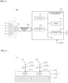
- Fig. 3 is a block diagram illustrating one example of the hardware configuration of the deep part thermometer 500 according to the embodiment 1.
- Symbol 200 indicates a temperature measuring unit.
- the deep part thermometer 500 according to the embodiment 1 may be configured to include: the deep part temperature measuring probe 1 according to the embodiment 1 described above; and a deep part temperature estimating unit 210 that estimates a deep part temperature TB using respective temperatures measured by a pair of first region temperature sensors 21, 22 and a pair of second region temperature sensors 23, 24 of the deep part temperature measuring probe 1.
- the deep part temperature estimating unit 210 calculates the deep part temperature TB by a dual-heat flow method (by performing an arithmetic operation in accordance with a formula (10) described later, for example), and sets the calculated value as an estimated value.
- the deep part temperature estimating unit 210 can be formed of either a dedicated circuit or a general-use circuit. In the case where the deep part temperature estimating unit 210 is formed of the general-use circuit, the deep part temperature estimating unit 210 is realized by an information processing device (not indicated by a symbol) illustrated in Fig. 3 , for example.
- the information processing device that constitutes the deep part temperature estimating unit 210 includes a processor 211, a memory 212, an input/output interface 214, and a communication interface 215. These parts are connected to a bus BS.
- the processor 211 is operated in accordance with a program stored in a memory unit (the memory 212 and a storage not illustrated in the drawing) so as to perform a control of the respective units.
- the memory unit includes a non-volatile memory device (ROM or the like).
- ROM non-volatile memory device
- a boot program that is executed by the processor 211 at the time of starting the information processing device, a program that is dependent on a hardware of the information processing device and the like are stored.
- the storage not illustrated in the drawing is constituted of auxiliary memory devices such as a solid state drive (SDD) and a hard disk drive (HDD).
- the memory 212 suitably stores data and the like necessary for the processor 211 to perform various controls and processing.
- the processor 211 calculates a deep part temperature TB by putting temperatures T1 to T4 and the like into the formula (10) described later and sets the calculated deep part temperature TB as an estimated value.
- the deep part temperature estimating unit 210 may be also referred to as a function of the processor that estimates the deep part temperature TB by calculation.
- the input/output interface 214 performs inputting and outputting from the input/output devices (particularly, the temperature sensors 21, 22, 23, 24, 25 in this embodiment).
- the communication interface 215 receives data from other electronic equipment via a network or the like, and transmits the data to the processor 211. Further, the communication interface 215 transmits data that is generated by the processor 211 to the other electronic equipment via the network or the like.
- Fig. 4 is a thermal equivalent circuit diagram of the deep part temperature measuring probe 1 according to the embodiment 1.
- Ia indicates a heat flow (value) that flows through the first heat flow path 115
- Ib indicates a heat flow (value) that flows through the second heat flow path 125
- Ic indicates a heat flow (value) that flows through a heat resistance Rs (heat resistance value) between a subject deep part 9c and the surface of a subject 9a (skin) in the first heat flow measuring system 110
- Id indicates a heat flow (value) that flows through a heat resistance Rs (heat resistance value) between the subject deep part 9c and the surface of the subject 9a (skin) in the second heat flow measuring system 120.
- Formula (4) is established from the formula (3).
- TB T 1 + T 1 ⁇ T 3 ⁇ Rs / R 1
- Formula (8) is established from the formula (7).
- TB T 2 + T 2 ⁇ T 4 ⁇ Rs / R 2
- the inventors performed a provisional experiment based on such an idea, and determined a heat resistance ratio K using the relationship expressed in the formula (9). Then, by using the relationship expressed in the formula (10), a deep part temperature TB was calculated (estimated) based on the heat resistance ratio K determined in the provisional experiment and temperatures (T1, T2, T3, T4) that are measured by the temperature sensors (15, 16, 17, 18).
- a deep part temperature as TB
- a temperature measured by the sensor 21 disposed on a side of the subject 9 out of the pair of first region temperature sensors as T1
- a temperature measured by the sensor 22 disposed on the side of the subject 9 out of the pair of second region temperature sensors as T2
- a temperature measured by the sensor 23 disposed on a side opposite to the side of the subject 9 out of the pair of first region temperature sensors as T3
- formulas (2. 6) in the non-patent literature 1 correspond to the formula (10) in this specification.
- formulas (2. 6) in the non-patent literature 1 include errors.
- Fig. 5 is a cross-sectional view schematically illustrating "an experimental system” for empirically obtaining a heat resistance ratio K of the deep part temperature measuring probe 1.
- a water bath 130 having a large heat capacity is used in place of the subject deep part 9c, and the water bath 130 is disposed in a constant temperature and humidity bath (not illustrated in the drawing).
- a temperature (an environment temperature) in the constant temperature and humidity bath is set to a predetermined temperature that falls within a range of from 10°C to 30°C.
- a water temperature (deep part temperature TB) is set to an approximately fixed value (about 37°C).
- Symbol 109 indicates a substitute subject, and a surface 109a of the substitute subject is formed of a substitute skin that is formed by simulating a biological skin made of a natural rubber sheet.
- Symbol 109b indicates a part that corresponds to an intermediate portion of the substitute subject
- symbol 109c indicates a part that corresponds to a deep part of the substitute subject.
- Symbol 131a indicates a support rod that supports a temperature sensor 131 (a thermistor or the like).
- the deep part temperature measuring probe 1 is disposed on an aluminum tub 133, and floats the aluminum tub 133 on water in the water bath 130.
- an actual deep part water temperature (deep part temperature TBr) in water bath 130 by measuring the temperature using the temperature sensor 131. Further, temperatures obtained by sensing using the temperature sensors 21 to 24 of the deep part temperature measuring probe 1 are measured by the temperature measuring unit 200 and are outputted to the deep part temperature estimating unit 210, and the deep part temperature estimating unit 210 performs an arithmetic operation based on such temperatures and hence, it is also possible to obtain (ii) an estimated deep part water temperature (deep part temperature TBp).
- a heat resistance ratio K can be determined by performing the following experiment (a preliminary experiment) as follows using the formula (9).
- the numerical value of the heat resistance ratio K determined as described above is stored in the memory 212 (see Fig. 3 ).
- the temperatures are measured by using the temperature sensors 21 to 24 and the temperature measuring unit 200, and the arithmetic operation is performed by the deep part temperature estimating unit 210 using the formula (10) thus calculating (estimating) the deep part temperature TB.
- the pair of first region temperature sensors 21, 22 is connected to each other through the through hole 15 formed just below the sensors Accordingly, provided that the board 10 includes only the hole and no particular treatment is applied to the board 10, only the air layer 30 is formed in the through hole 15 and hence, a heat resistance value R1 between the first region temperature sensors 21, 22 can be considerably increased.
- the deep part temperature measuring probe 1 can measure a temperature (deep part temperature TB) of the subject deep part 9c with high accuracy.
- thermal conductivity of air is 0.0241 [W/(mK)] (at a temperature of 0°C)
- the thermal conductivity of a material used for forming the board 10 is a value that falls within a range of 0.28 to 0.34 [W/(mK)].
- the air layer 30 is formed in the through hole 15. Accordingly, to observe the deep part temperature measuring probe 1 from a viewpoint of heat resistance, the air layer 30 can provide an incomparatively large heat resistance value to the deep part temperature measuring probe 1 compared to the members that constitute the board 10 and the like. Accordingly, the heat resistance value R1 of the first heat flow path 115 that is formed of the air layer 15 can be outstandingly increased. Accordingly, the structure for making the difference between the heat resistance value R1 of the first heat flow path 115 and the heat resistance value R2 of the second heat flow path 125 can be realized with the extremely simple structure.
- the deep part thermometer 500 according to the embodiment 1 includes: the deep part temperature measuring probe 1 according to the embodiment 1; and the deep part temperature estimating unit 210 that estimates a deep part temperature using the respective temperatures measured by the pair of first region temperature sensors 21, 22 and the pair of second region temperature sensors 23, 24 of the deep part temperature measuring probe 1.
- the deep part thermometer 500 includes the deep part temperature measuring probe 1 that can measure a temperature (deep part temperature TB) of the subject deep part 9c with high accuracy even when the thin board 10 is used and hence, it is possible to provide a small-sized and highly accurate deep part thermometer.
- the deep part thermometer 500 is configured to estimate the deep part temperature TB by putting the heat resistance ratio K that is preliminarily determined using the relationship expressed by the above-mentioned formula (9) for obtaining the heat resistance ratio K and the temperatures T1, T2, T3 and T4 that are measured by applying probing to the subject 9 into the relationship expressed by the above-mentioned formula (10).
- the heat resistance ratio K is influenced by a heat flux in a diffusion mode besides a linear heat flux. Accordingly, there may be a case where a heat resistance ratio K that is theoretically obtained based on known thermal conductivities of materials that are used for forming the respective heat flow paths differs from an actual accurate heat resistance ratio K.
- a heat resistance ratio K that is theoretically obtained based on known thermal conductivities of materials that are used for forming the respective heat flow paths differs from an actual accurate heat resistance ratio K.
- FIG. 6 is a cross-sectional view illustrating a deep part temperature measuring probe 2 according to an embodiment 2.
- the deep part temperature measuring probe 2 according to the embodiment 2 has basically substantially the same configuration as the deep part temperature measuring probe 1 according to the embodiment 1.
- the deep part temperature measuring probe 2 according to the embodiment 2 differs from the deep part temperature measuring probe 1 according to the embodiment 1 with respect to the manner of forming the configuration of a first heat flow path 115.
- a heat insulating sheet 31 is disposed in a through hole 15.
- the heat insulating sheet 31 is a sheet having thermal conductivity substantially equal to the thermal conductivity of air.
- a sheet in which porous particles made of silica gel that contains foamed air is impregnated and the like is named as the heat insulating sheet 31.
- the heat insulating sheet 31 may be filled in the inner space of the through hole 15 in a state that the heat insulating sheet 31 is formed in a suitable stereoscopic shape such as a corrugated shape, a folded state where crests and valleys are formed alternately, or a randomly rounded shape and the like.
- a suitable stereoscopic shape such as a corrugated shape, a folded state where crests and valleys are formed alternately, or a randomly rounded shape and the like.
- the heat insulating sheet 31 By arranging the heat insulating sheet 31 in the through hole 15 that forms the first heat flow path 15, it is possible to allow the heat insulating sheet 31 to obstruct the movement of air in the through hole 15 and hence, the occurrence of convection in the through hole 15 can be suppressed. Accordingly, the transmission and the reception of heat caused by "convection" in the first heat flow path 115 can be suppressed and hence, the direct transmission and reception of heat by the "transfer" via the air layer 30 and the heat insulating sheet 31 is mainly performed. Accordingly, it is possible to realize a more ideal state from a viewpoint of a thermal circuit and hence, the deep part temperature measuring probe 2 can measure a deep part temperature with higher accuracy.
- the deep part temperature measuring probe 2 according to the embodiment 2 has basically substantially the same configuration as the deep part temperature measuring probe 1 according to the embodiment 1 except for the manner of constituting the configuration of the first heat flow path 115. Accordingly, the deep part temperature measuring probe 2 according to the embodiment 2 has the corresponding advantageous effects amongst the advantageous effects that the deep part temperature measuring probe 1 according to the embodiment 1 has.
- FIG. 7 is a cross-sectional view illustrating a deep part temperature measuring probe 3 according to an embodiment 3.
- the deep part temperature measuring probe 3 according to the embodiment 3 has basically substantially the same configuration as the deep part temperature measuring probe 1 according to the embodiment 1.
- the deep part temperature measuring probe 3 according to the embodiment 3 differs from the deep part temperature measuring probe 1 according to the embodiment 1 with respect to the configuration of a board 10 and the configuration of a first heat flow path 115.
- the board 10 is formed of a glass board, and the inside of a through hole 15 is configured to be brought into a state 32 in vacuum or in a substantially vacuum state.
- thermal conductivity of the through hole 15 can be further lowered compared to the case where the through hole 15 is formed of the air layer 30. Accordingly, a heat resistance value R1 between a pair of first region temperature sensors 21, 22 can be further increased.
- the deep part temperature measuring probe 3 according to the embodiment 3 has basically substantially the same configuration as the deep part temperature measuring probe 1 according to the embodiment 1 except for the manner of constituting the configuration of the board 10 and the configuration of the first heat flow path 115. Accordingly, the deep part temperature measuring probe 3 according to the embodiment 3 has the corresponding advantageous effects amongst the advantageous effects that the deep part temperature measuring probe 1 according to the embodiment 1 has.
- Fig. 8 is a view illustrating a deep part temperature measuring probe 4 according to an embodiment 4.
- Fig. 8(a) is a cross-sectional view of the deep part temperature measuring probe 4 taken along a line D-D in Fig. 8(b).
- Fig. 8(b) is a plan view of deep part temperature measuring probe 4 according to the embodiment 4 when the deep part temperature measuring probe 4 is viewed along an arrow C in Fig. 8(a) .
- the deep part temperature measuring probe 4 according to the embodiment 4 includes basically substantially the same configuration as the deep part temperature measuring probes 1, 2, 3 according to the embodiments 1,2, 3. However, the deep part temperature measuring probe 4 according to the embodiment 4 differs from the deep part temperature measuring probes 1, 2, 3 according to the embodiments 1,2, 3 with respect to a point that the deep part temperature measuring probe 4 according to the embodiment 4 is configured to suppress the thermal interference between a first heat flow path 115 and a second heat flow path 125.
- an air layer 40 is formed in the board 10 between a first region 11 and a second region 12.
- a through hole that penetrates the board 10 is formed between a front surface 10a and a back surface 10b of the board 10, and the air layer 40 may be formed of air disposed in the through hole.
- the through hole may be configured as an elongated hole that penetrates a the board 10 in a most portion of a lateral region of the temperature sensor as illustrated in Fig. 8 .
- the deep part temperature measuring probe 4 has such a configuration and hence, the air layer 40 that forms a heat insulating body can block the thermal conduction between the first region 11 where the first heat flow path 115 is formed and the second region 12 where the second heat flow path 125 is formed. Accordingly, the thermal interference between the first heat flow path 115 and the second heat flow path 125 can be made small and hence, independency of both heat flow paths can be increased whereby the measurement of a deep part temperature can be performed with higher accuracy.
- the deep part temperature measuring probe 4 according to the embodiment 4 has basically substantially the same configuration as the deep part temperature measuring probes 1, 2, 3 according to the embodiments 1, 2, 3 except for the point that the deep part temperature measuring probe 4 according to the embodiment 4 is configured to suppress the thermal interference between the first heat flow path 115 and the second heat flow path 125. Accordingly, the deep part temperature measuring probe 4 according to the embodiment 4 has the corresponding advantageous effects amongst the advantageous effects that the deep part temperature measuring probes 1, 2, 3 according to the embodiments 1, 2, 3 have.
- Fig. 9 is a cross-sectional view illustrating a deep part temperature measuring probe 5 according to the modification 1.
- the metal 37 copper can be adopted as an example. It is considered that thermal conductivity of copper is 403 [W/(mK)] (at 0°[C]) and is incomparably large compared to thermal conductivities of members that constitute the board 10 and the like. From a viewpoint of heat resistance, it is possible to allow the metal 37 to have an incomparatively small heat resistance value compared to the members that constitute the board 10 and the like. Accordingly, a heat resistance value R2 of the second heat flow path 125 that is formed of metal 37 can be made considerably small and hence, it is possible to easily secure the difference between the heat resistance value R2 of the second heat flow path 125 and the heat resistance value R1 of the first heat flow path 115.
- the present invention is not limited to such a configuration.
- the present invention provides the structure that does not have an electrically connection by forming only a gap (an air layer) between the thermal pad 29 and the land 13b of the wiring pattern 13 without interposing "solder 51" therebetween (not illustrated in the drawing). Even with such a structure, thermal coupling can be performed between the pair of second region temperature sensors 23, 24.
- the present invention is not limited to such a configuration.
- the temperature sensors 21 to 24 may be formed of an IC of a wafer level chip size package (WL-CSP) (modification 2).
- the temperature sensors 21 to 24 may be constituted in a form that bare chips are directly mounted on the board 10 (modification 3).
- the temperature sensors may each be formed of a temperature sensor such as a thermocouple in place of an IC.
- the description is made with respect to the case where, to thermally separate the first region 11 and the second region 12 from each other, the "elongated hole shaped" (as viewed in a plan view) penetration hole that penetrates the board 10 between the front surface 10a and the back surface 10b is formed in the board 10.
- the present invention is not limited to such a configuration.
- the configuration may be adopted where, in place of the elongated hole, spot-like through holes that have a "true circular shape (as viewed in a plan view) and penetrate the board 10 are arranged in a row parallel to each other (modification 4).
- a cavity is formed in the inside of the board 10 in the thickness direction, and an air layer 40 may be formed by filling the cavity with air (modification 5).
- an air layer 41 may be also formed in the board 10 between a region that is constituted of a first region 11 and a second region 12 and a temperature sensor 25.
- the air layer 41 may be formed of an elongated hole that penetrates the most of a region of the board disposed on a side of temperature sensor 25 in a lateral direction.
- the air layer 40 is disposed on the left side, the air layer 41 is disposed on the right side, and an atmosphere 8 (an air layer) is disposed on the upper side and the lower side.
- the air layer 40 is disposed on the right side, and the atmosphere 8 (the air layer) is disposed on the left side, the upper side and the lower side. That is, the air layer is disposed around the first region 11 and/or the second region 12.
- a heat flux between a pair of temperature sensors disposed on a front surface and a back surface of the board 10 is covered/surrounded by the air layer having low thermal conductivity. Accordingly, a heat flow cannot move in a lateral direction as viewed in a plan view and hence, the heat flow is formed of only an ideal heat flow that flows only in a vertical direction and hence, the accuracy of a measurable deep part temperature can be further enhanced. Further, by forming the elongated hole such that a region around the temperature sensor is covered as much as possible or in a continuous manner (around four side, if possible), the more ideal heat flow that flows only in a vertical direction can be obtained and hence, the accuracy of the measurable deep part temperature can be further enhanced. Further, a heat insulating sheet 31 having substantially the same thermal conductivity as air may be disposed in the respective air layers 40, 41.
- Fig. 10 is constituted of cross-sectional views illustrating main parts of deep part temperature measuring probes 6, 7 according to the modification 2 and the modification 3.
- Fig. 11 is constituted of views illustrating deep part temperature measuring probes 4', 4" according to the modifications 4, 5.
- Fig. 11(a) is a plan view of the deep part temperature measuring probe 4'
- Fig. 11(b) is a cross-sectional view of the deep part temperature measuring probe 4' illustrating a cross section taken along a line E-E in Fig. 11(a).
- Fig. 11(c) is a plan view of the deep part temperature measuring probe 4"
- Fig. 11(d) is a cross-sectional view of the deep part temperature measuring probe 4" taken along a line F-F in Fig. 11(c) .
Landscapes
- Physics & Mathematics (AREA)
- General Physics & Mathematics (AREA)
- Health & Medical Sciences (AREA)
- Life Sciences & Earth Sciences (AREA)
- Heart & Thoracic Surgery (AREA)
- Surgery (AREA)
- Engineering & Computer Science (AREA)
- Biomedical Technology (AREA)
- Biophysics (AREA)
- Medical Informatics (AREA)
- Molecular Biology (AREA)
- Pathology (AREA)
- Animal Behavior & Ethology (AREA)
- General Health & Medical Sciences (AREA)
- Public Health (AREA)
- Veterinary Medicine (AREA)
- Measuring And Recording Apparatus For Diagnosis (AREA)
- Measuring Temperature Or Quantity Of Heat (AREA)
Applications Claiming Priority (2)
| Application Number | Priority Date | Filing Date | Title |
|---|---|---|---|
| JP2022105509 | 2022-06-30 | ||
| PCT/JP2023/017069 WO2024004375A1 (fr) | 2022-06-30 | 2023-05-01 | Sonde pour mesure de température en profondeur et thermomètre de profondeur |
Publications (1)
| Publication Number | Publication Date |
|---|---|
| EP4548836A1 true EP4548836A1 (fr) | 2025-05-07 |
Family
ID=89381949
Family Applications (1)
| Application Number | Title | Priority Date | Filing Date |
|---|---|---|---|
| EP23830827.4A Pending EP4548836A1 (fr) | 2022-06-30 | 2023-05-01 | Sonde pour mesure de température en profondeur et thermomètre de profondeur |
Country Status (5)
| Country | Link |
|---|---|
| US (1) | US20250354877A1 (fr) |
| EP (1) | EP4548836A1 (fr) |
| JP (1) | JP7702181B2 (fr) |
| CN (1) | CN119421659A (fr) |
| WO (1) | WO2024004375A1 (fr) |
Families Citing this family (2)
| Publication number | Priority date | Publication date | Assignee | Title |
|---|---|---|---|---|
| WO2025142376A1 (fr) * | 2023-12-28 | 2025-07-03 | 公立大学法人公立諏訪東京理科大学 | Sonde pour mesure de température de partie profonde et thermomètre de partie profonde |
| WO2026042398A1 (fr) * | 2024-08-19 | 2026-02-26 | 公立大学法人公立諏訪東京理科大学 | Sonde de mesure, thermomètre et procédé de mesure de température centrale |
Family Cites Families (5)
| Publication number | Priority date | Publication date | Assignee | Title |
|---|---|---|---|---|
| JP6398808B2 (ja) * | 2015-03-12 | 2018-10-03 | オムロン株式会社 | 内部温度測定装置及びセンサパッケージ |
| JP6398807B2 (ja) * | 2015-03-12 | 2018-10-03 | オムロン株式会社 | 温度差測定装置 |
| JP6969665B2 (ja) | 2018-03-02 | 2021-11-24 | 株式会社村田製作所 | 深部体温計 |
| EP3699570A1 (fr) * | 2019-02-19 | 2020-08-26 | Nederlandse Organisatie voor toegepast- natuurwetenschappelijk onderzoek TNO | Capteur de température corporelle centrale et son procédé de fabrication |
| JP7528674B2 (ja) | 2020-09-25 | 2024-08-06 | 株式会社三洋物産 | 遊技機 |
-
2023
- 2023-05-01 EP EP23830827.4A patent/EP4548836A1/fr active Pending
- 2023-05-01 JP JP2024530334A patent/JP7702181B2/ja active Active
- 2023-05-01 WO PCT/JP2023/017069 patent/WO2024004375A1/fr not_active Ceased
- 2023-05-01 CN CN202380049725.7A patent/CN119421659A/zh active Pending
- 2023-05-01 US US18/871,597 patent/US20250354877A1/en active Pending
Also Published As
| Publication number | Publication date |
|---|---|
| JP7702181B2 (ja) | 2025-07-03 |
| CN119421659A (zh) | 2025-02-11 |
| US20250354877A1 (en) | 2025-11-20 |
| WO2024004375A1 (fr) | 2024-01-04 |
| JPWO2024004375A1 (fr) | 2024-01-04 |
Similar Documents
| Publication | Publication Date | Title |
|---|---|---|
| US11686626B2 (en) | Apparatus, systems, and methods for non-invasive thermal interrogation | |
| EP4548836A1 (fr) | Sonde pour mesure de température en profondeur et thermomètre de profondeur | |
| US12196622B2 (en) | Temperature measurement device and temperature measurement method | |
| JP7515837B2 (ja) | 生体データ測定装置 | |
| US11717170B2 (en) | Body core temperature sensor with two TEGs | |
| US10551252B2 (en) | Internal temperature measuring apparatus and sensor package | |
| EP3431946B1 (fr) | Thermomètre corporel profond | |
| CN114594141B (zh) | 集成电子鼻传感结构及其使用方法 | |
| CN102082107A (zh) | 芯片测温方法和测温装置 | |
| JP7778363B2 (ja) | 深部体温計測用プローブ及び深部体温計 | |
| CN117388524A (zh) | 风速风向传感器、风速风向检测设备及方法 | |
| WO2025142376A1 (fr) | Sonde pour mesure de température de partie profonde et thermomètre de partie profonde | |
| JP7351416B2 (ja) | 設置状態判定方法、および設置状態判定システム | |
| US12320768B2 (en) | Measuring device and measuring system | |
| WO2026042398A1 (fr) | Sonde de mesure, thermomètre et procédé de mesure de température centrale | |
| US20240272015A1 (en) | Sensing assembly | |
| KR20250113989A (ko) | 유체 온도 값을 제공하기 위한 장치, 시스템 및 방법 그리고 시스템을 포함하는 차량 | |
| JP7392837B2 (ja) | 温度測定装置および温度測定方法 | |
| JP2026015237A (ja) | ガスを検出するための熱伝導率センサ | |
| JP3990873B2 (ja) | 計測センサ及び計測装置 | |
| JP2016170044A (ja) | 内部温度測定装置及び温度差測定モジュール |
Legal Events
| Date | Code | Title | Description |
|---|---|---|---|
| STAA | Information on the status of an ep patent application or granted ep patent |
Free format text: STATUS: THE INTERNATIONAL PUBLICATION HAS BEEN MADE |
|
| PUAI | Public reference made under article 153(3) epc to a published international application that has entered the european phase |
Free format text: ORIGINAL CODE: 0009012 |
|
| STAA | Information on the status of an ep patent application or granted ep patent |
Free format text: STATUS: REQUEST FOR EXAMINATION WAS MADE |
|
| 17P | Request for examination filed |
Effective date: 20241118 |
|
| AK | Designated contracting states |
Kind code of ref document: A1 Designated state(s): AL AT BE BG CH CY CZ DE DK EE ES FI FR GB GR HR HU IE IS IT LI LT LU LV MC ME MK MT NL NO PL PT RO RS SE SI SK SM TR |
|
| DAV | Request for validation of the european patent (deleted) | ||
| DAX | Request for extension of the european patent (deleted) |