EP4549059A1 - Werkzeugmaschine und verfahren zur ausrichtung einer werkzeugmaschine - Google Patents
Werkzeugmaschine und verfahren zur ausrichtung einer werkzeugmaschine Download PDFInfo
- Publication number
- EP4549059A1 EP4549059A1 EP22949422.4A EP22949422A EP4549059A1 EP 4549059 A1 EP4549059 A1 EP 4549059A1 EP 22949422 A EP22949422 A EP 22949422A EP 4549059 A1 EP4549059 A1 EP 4549059A1
- Authority
- EP
- European Patent Office
- Prior art keywords
- spindle
- machine tool
- shaft alignment
- variance
- physical quantity
- Prior art date
- Legal status (The legal status is an assumption and is not a legal conclusion. Google has not performed a legal analysis and makes no representation as to the accuracy of the status listed.)
- Pending
Links
Images








Classifications
-
- G—PHYSICS
- G05—CONTROLLING; REGULATING
- G05B—CONTROL OR REGULATING SYSTEMS IN GENERAL; FUNCTIONAL ELEMENTS OF SUCH SYSTEMS; MONITORING OR TESTING ARRANGEMENTS FOR SUCH SYSTEMS OR ELEMENTS
- G05B19/00—Program-control systems
- G05B19/02—Program-control systems electric
- G05B19/18—Numerical control [NC], i.e. automatically operating machines, in particular machine tools, e.g. in a manufacturing environment, so as to execute positioning, movement or co-ordinated operations by means of program data in numerical form
- G05B19/404—Numerical control [NC], i.e. automatically operating machines, in particular machine tools, e.g. in a manufacturing environment, so as to execute positioning, movement or co-ordinated operations by means of program data in numerical form characterised by control arrangements for compensation, e.g. for backlash, overshoot, tool offset, tool wear, temperature, machine construction errors, load, inertia
-
- B—PERFORMING OPERATIONS; TRANSPORTING
- B23—MACHINE TOOLS; METAL-WORKING NOT OTHERWISE PROVIDED FOR
- B23Q—DETAILS, COMPONENTS, OR ACCESSORIES FOR MACHINE TOOLS, e.g. ARRANGEMENTS FOR COPYING OR CONTROLLING; MACHINE TOOLS IN GENERAL CHARACTERISED BY THE CONSTRUCTION OF PARTICULAR DETAILS OR COMPONENTS; COMBINATIONS OR ASSOCIATIONS OF METAL-WORKING MACHINES, NOT DIRECTED TO A PARTICULAR RESULT
- B23Q15/00—Automatic control or regulation of feed movement, cutting velocity or position of tool or work
- B23Q15/007—Automatic control or regulation of feed movement, cutting velocity or position of tool or work while the tool acts upon the workpiece
- B23Q15/12—Adaptive control, i.e. adjusting itself to have a performance which is optimum according to a preassigned criterion
-
- B—PERFORMING OPERATIONS; TRANSPORTING
- B23—MACHINE TOOLS; METAL-WORKING NOT OTHERWISE PROVIDED FOR
- B23Q—DETAILS, COMPONENTS, OR ACCESSORIES FOR MACHINE TOOLS, e.g. ARRANGEMENTS FOR COPYING OR CONTROLLING; MACHINE TOOLS IN GENERAL CHARACTERISED BY THE CONSTRUCTION OF PARTICULAR DETAILS OR COMPONENTS; COMBINATIONS OR ASSOCIATIONS OF METAL-WORKING MACHINES, NOT DIRECTED TO A PARTICULAR RESULT
- B23Q15/00—Automatic control or regulation of feed movement, cutting velocity or position of tool or work
- B23Q15/20—Automatic control or regulation of feed movement, cutting velocity or position of tool or work before or after the tool acts upon the workpiece
- B23Q15/22—Control or regulation of position of tool or workpiece
-
- B—PERFORMING OPERATIONS; TRANSPORTING
- B23—MACHINE TOOLS; METAL-WORKING NOT OTHERWISE PROVIDED FOR
- B23Q—DETAILS, COMPONENTS, OR ACCESSORIES FOR MACHINE TOOLS, e.g. ARRANGEMENTS FOR COPYING OR CONTROLLING; MACHINE TOOLS IN GENERAL CHARACTERISED BY THE CONSTRUCTION OF PARTICULAR DETAILS OR COMPONENTS; COMBINATIONS OR ASSOCIATIONS OF METAL-WORKING MACHINES, NOT DIRECTED TO A PARTICULAR RESULT
- B23Q17/00—Arrangements for observing, indicating or measuring on machine tools
- B23Q17/12—Arrangements for observing, indicating or measuring on machine tools for indicating or measuring vibration
-
- B—PERFORMING OPERATIONS; TRANSPORTING
- B23—MACHINE TOOLS; METAL-WORKING NOT OTHERWISE PROVIDED FOR
- B23B—TURNING; BORING
- B23B25/00—Accessories or auxiliary equipment for turning-machines
- B23B25/06—Measuring, gauging, or adjusting equipment on turning-machines for setting-on, feeding, controlling, or monitoring the cutting tools or work
-
- B—PERFORMING OPERATIONS; TRANSPORTING
- B23—MACHINE TOOLS; METAL-WORKING NOT OTHERWISE PROVIDED FOR
- B23B—TURNING; BORING
- B23B3/00—General-purpose turning-machines or devices, e.g. centre lathes with feed rod and lead screw; Sets of turning-machines
- B23B3/30—Turning-machines with two or more working-spindles, e.g. in fixed arrangement
-
- G—PHYSICS
- G05—CONTROLLING; REGULATING
- G05B—CONTROL OR REGULATING SYSTEMS IN GENERAL; FUNCTIONAL ELEMENTS OF SUCH SYSTEMS; MONITORING OR TESTING ARRANGEMENTS FOR SUCH SYSTEMS OR ELEMENTS
- G05B2219/00—Program-control systems
- G05B2219/30—Nc systems
- G05B2219/37—Measurements
- G05B2219/37434—Measuring vibration of machine or workpiece or tool
-
- G—PHYSICS
- G05—CONTROLLING; REGULATING
- G05B—CONTROL OR REGULATING SYSTEMS IN GENERAL; FUNCTIONAL ELEMENTS OF SUCH SYSTEMS; MONITORING OR TESTING ARRANGEMENTS FOR SUCH SYSTEMS OR ELEMENTS
- G05B2219/00—Program-control systems
- G05B2219/30—Nc systems
- G05B2219/50—Machine tool, machine tool null till machine tool work handling
- G05B2219/50152—Align axis cylinder, tube with rotation axis machine
Definitions
- the present disclosure relates to a machine tool and a machine tool alignment method.
- PTL 1 describes a machine tool that detects abnormalities based on data related to the vibration of a clamp configured to be able to implement fastening and attachment of a workpiece or tool.
- Another known type of machine tool has a main spindle and a tailstock spindle that extend along the same axis.
- the workpiece is held at one end and the other end thereof with the respective clamps of the main spindle and the tailstock spindle.
- the main and tailstock spindles could be axially misaligned from each other (shaft misalignment or misalignment).
- PTL 2 describes correcting an axial misalignment between the main spindle and the tailstock spindle based on data acquired by measurements of the axial center of a rod member held on the main spindle and the axial center of a rod member held on the tailstock spindle opposite the main spindle, the measurement being taken using an outer diameter gauge.
- An object of the present disclosure is to facilitate shaft alignment in machine tools.
- An aspect of the present disclosure is a machine tool comprising:
- Another aspect of the present disclosure is a machine tool alignment method for a machine tool, the machine tool including:
- Yet another aspect of the present disclosure is a program for causing a computer to execute the machine tool alignment method specified above or a storage medium storing this program in a non-temporary manner.
- the present disclosure facilitates shaft alignment in machine tools.
- a machine tool that is one aspect of the present disclosure includes: a first spindle holding one end of a workpiece; a second spindle holding the other end of the workpiece; a sensor detecting a physical quantity related to a vibration during synchronous rotation of the first spindle and the second spindle with the workpiece being held by the first spindle and the second spindle; and a controller performing shaft alignment between the first spindle and the second spindle based on the physical quantity.
- first spindle and second spindle be axially aligned. This is why shaft alignment is performed during the manufacture of machine tools. Even if shaft alignment is performed during the manufacture, the machine tool may sometimes experience a shaft misalignment due to changes over time or depending on operating conditions. Therefore, shaft alignment is sometimes performed before using the machine tool. Namely, the controller performs shaft alignment during manufacture or prior to use of the machine tool.
- the shaft alignment between the first spindle and second spindle is performed while the first and second spindles are holding the same workpiece and rotating in sync.
- the phrase "while rotating in sync" may be any situation where the first and second spindles are rotating synchronously as a result including, for example, a case where the first and second spindles are being controlled to rotate in sync, or a case where the first and second spindles having a mechanism for rotating synchronously are rotating.
- the sensor can be any sensor capable of detecting a physical quantity relating to the vibration that occurs in the first or second spindle such as, for example, a vibration sensor (including an acceleration sensor) or a position sensor.
- Fig. 1 is a diagram illustrating one example of a machine tool according to this embodiment.
- the machine tool 1 includes a first spindle 11 and a first headstock 12 that rotatably supports the first spindle 11.
- the first spindle 11 includes a first clamp 13 operable to fasten and to allow attachment of a workpiece W at one end.
- the machine tool 1 also includes a second spindle 21 extending on the substantially same axial line as that of the first spindle 11 and a second headstock 22 that rotatably supports this second spindle 21.
- the second spindle 21 may be a tailstock spindle.
- the second spindle 21 includes a second clamp 23 operable to fasten and to allow attachment of the workpiece W at the other end.
- An adjustment mechanism 24 is provided between the second spindle 21 and the second headstock 22 for moving the second spindle 21 relative to the second headstock 22.
- the adjustment mechanism 24 is configured to relatively move the second spindle 21 in two directions, for example, along the X axis and the Y axis.
- the adjustment mechanism 24 is configured to include a gear and an actuator to drive this gear, for example.
- the first headstock 12 and the second headstock 22 are fixed on the same structure such as a machine bed 100, for example, so that their relative positions do not change. In Fig.
- the axial direction of the first spindle 11 and second spindle (left and right direction in Fig. 1 ) shall be referred to as the Z-axis direction
- the direction perpendicular to the Z axis and parallel to the top surface of the machine bed 100 (up and down direction in Fig. 1 ) shall be referred to as the Y-axis direction
- the direction perpendicular to the top surface of the machine bed 100 (front and back direction in Fig. 1 ) shall be referred to as the X-axis direction.
- a clamp actuator (not shown) made up of cylinders and pistons, for example, can cause the first clamp 13 and second clamp 23 to fasten the workpiece W.
- the first spindle 11 and second spindle 21 are rotated in sync so that the workpiece W is cut, for example, with a tool.
- the phrase “clamping a workpiece W with the first spindle 11” shall mean clamping the workpiece W with the first clamp 13.
- the phrase “clamping a workpiece W with the second spindle 21” shall mean clamping the workpiece with the second clamp 23.
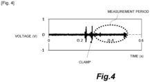
- a vibration sensor 25 is disposed on the second spindle 21 to measure the vibration of the second spindle 21.
- the vibration sensor 25 may measure the vibration of the second spindle 21 only during the shaft alignment between the first spindle 11 and the second spindle 21, or, it may continuously measure the vibration of the second spindle 21 during the operation of the machine tool 1. The timing of measurement by the vibration sensor 25 may be changed as required.
- the vibration sensor 25 can be disposed anywhere as long as it can measure the vibration of the second clamp 23.
- the vibration sensor 25 may be disposed as close as possible to the second clamp 23, for example.
- an acceleration sensor is used as the vibration sensor 25.
- An acceleration sensor is a sensor capable of measuring acceleration in one direction, for example, the X-axis direction or Y-axis direction shown in Fig. 1 .
- a sensor capable of measuring acceleration in two directions or more may be used.
- the vibration sensor 25 is not limited to an acceleration sensor, and may be a distance sensor or the like, for example. Two or more sensors may be used.
- the phrase "readings of the vibration sensor 25" may refer to either voltages that are the outputs of the vibration sensor 25, or values converted from voltage to represent acceleration or vibration. The conversion is performed by a shaft alignment unit 402 to be described later.
- the machine tool 1 includes a controller 40.
- the controller 40 is a computer that controls the machine tool 1.
- Fig. 2 is a schematic block diagram illustrating one example of the configuration of the machine tool 1 according to this embodiment.
- the controller 40 has a configuration of a common computer.
- the controller 40 includes a processor 41, a main storage unit 42, an auxiliary storage unit 43, an input unit 44, and an output unit 45. These units are interconnected with a bus. Sensors including the vibration sensor 25 are connected to the bus with an interface so that signals from these sensors are input to the controller 40. Also connected to the bus via interfaces are an actuator that rotates the first spindle 11, an actuator that rotates the second spindle 21, an actuator that causes the first clamp 13 to fasten and open, an actuator that causes the second clamp 23 to fasten and open, the adjustment mechanism 24, etc., so that control signals are sent from the controller 40 to these components.
- the processor 41 is a CPU (Central Processing Unit) or a DSP (Digital Signal Processor) and the like.
- the processor 41 controls the machine tool 1 and performs various information processing operations.
- the main storage unit 42 is a RAM (Random Access Memory) or a ROM (Read Only Memory) and the like.
- the auxiliary storage unit 43 is an EPROM (Erasable Programmable ROM), an HDD (Hard Disk Drive), removable media, and so on.
- An operating system (OS) and various programs and tables are stored in the auxiliary storage unit 43.
- the processor 41 loads a program stored in the auxiliary storage unit 43 to a work area of the main storage unit 42 and executes it. Various constituent parts are controlled through the execution of the program.
- the controller 40 thus implements the functions that serve predetermined purposes.
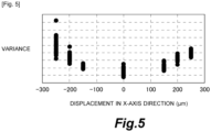
- the displacement in the X-axis direction and the variance have a correlation; the larger the absolute value of displacement in the X-axis direction, the higher the variance.
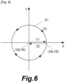
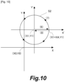
- shaft alignment between the first spindle 11 and second spindle 21 is performed using this phenomenon. Namely, the shaft alignment between the first spindle 11 and the second spindle 21 is carried out by moving the second spindle 21 in a direction in which the variance of the readings of the vibration sensor 25 reduces.
Landscapes
- Engineering & Computer Science (AREA)
- Mechanical Engineering (AREA)
- Human Computer Interaction (AREA)
- Manufacturing & Machinery (AREA)
- Physics & Mathematics (AREA)
- General Physics & Mathematics (AREA)
- Automation & Control Theory (AREA)
- Automatic Control Of Machine Tools (AREA)
- Numerical Control (AREA)
Applications Claiming Priority (1)
| Application Number | Priority Date | Filing Date | Title |
|---|---|---|---|
| PCT/JP2022/026305 WO2024004149A1 (ja) | 2022-06-30 | 2022-06-30 | 工作機械、及び、工作機械の軸合わせ方法 |
Publications (2)
| Publication Number | Publication Date |
|---|---|
| EP4549059A1 true EP4549059A1 (de) | 2025-05-07 |
| EP4549059A4 EP4549059A4 (de) | 2026-04-22 |
Family
ID=89382463
Family Applications (1)
| Application Number | Title | Priority Date | Filing Date |
|---|---|---|---|
| EP22949422.4A Pending EP4549059A4 (de) | 2022-06-30 | 2022-06-30 | Werkzeugmaschine und verfahren zur ausrichtung einer werkzeugmaschine |
Country Status (5)
| Country | Link |
|---|---|
| US (1) | US20250360588A1 (de) |
| EP (1) | EP4549059A4 (de) |
| KR (1) | KR20250002809A (de) |
| CN (1) | CN119365284A (de) |
| WO (1) | WO2024004149A1 (de) |
Family Cites Families (10)
| Publication number | Priority date | Publication date | Assignee | Title |
|---|---|---|---|---|
| JPH01309647A (ja) | 1988-06-07 | 1989-12-14 | Horiken:Kk | 穀類の連続処理装置 |
| JP2702575B2 (ja) * | 1989-12-15 | 1998-01-21 | ファナック株式会社 | ワーク交換方法 |
| JPH11309647A (ja) * | 1998-04-28 | 1999-11-09 | Star Micronics Co Ltd | Nc自動旋盤の芯出し方法 |
| JPH11320340A (ja) * | 1998-05-01 | 1999-11-24 | Citizen Watch Co Ltd | 自動旋盤の心出し用測定装置及び心出し方法 |
| DE102015012818A1 (de) * | 2015-10-05 | 2017-04-06 | Liebherr-Verzahntechnik Gmbh | Bearbeitungskopf mit Wuchteinrichtung |
| JP7125096B2 (ja) * | 2018-05-16 | 2022-08-24 | 有限会社高峰精機 | ワークの芯出し方法 |
| JP7281264B2 (ja) | 2018-09-28 | 2023-05-25 | シチズン時計株式会社 | 工作機械及びその作動方法 |
| JP7323758B2 (ja) * | 2018-11-22 | 2023-08-09 | スター精密株式会社 | 旋盤 |
| WO2020209134A1 (ja) * | 2019-04-11 | 2020-10-15 | シチズン時計株式会社 | 工作機械及び検知方法 |
| JP7604489B2 (ja) * | 2020-06-30 | 2024-12-23 | シチズン時計株式会社 | 工作機械、工作機械の制御方法 |
-
2022
- 2022-06-30 EP EP22949422.4A patent/EP4549059A4/de active Pending
- 2022-06-30 US US18/876,311 patent/US20250360588A1/en active Pending
- 2022-06-30 WO PCT/JP2022/026305 patent/WO2024004149A1/ja not_active Ceased
- 2022-06-30 CN CN202280097071.0A patent/CN119365284A/zh active Pending
- 2022-06-30 KR KR1020247040878A patent/KR20250002809A/ko active Pending
Also Published As
| Publication number | Publication date |
|---|---|
| CN119365284A (zh) | 2025-01-24 |
| KR20250002809A (ko) | 2025-01-07 |
| EP4549059A4 (de) | 2026-04-22 |
| WO2024004149A1 (ja) | 2024-01-04 |
| US20250360588A1 (en) | 2025-11-27 |
Similar Documents
| Publication | Publication Date | Title |
|---|---|---|
| JP6295070B2 (ja) | 多軸工作機械の幾何誤差同定方法及び多軸工作機械 | |
| JP5793200B2 (ja) | 工作機械の切削力検出装置、切削力検出方法、加工異常検出方法、および加工条件制御システム | |
| WO2013150905A1 (ja) | 切削加工システム及び方法 | |
| JP5968749B2 (ja) | 幾何誤差同定方法と当該幾何誤差同定方法を使用した数値制御方法、数値制御装置及びマシニングセンタ | |
| JP2017027360A (ja) | 機械の誤差補償システム及び誤差補償方法、誤差補償プログラム | |
| CN104972361A (zh) | 计测系统 | |
| JP2011020233A (ja) | 機上測定方法及び測定装置 | |
| JP7424759B2 (ja) | 主軸異常検出装置 | |
| CN117884949A (zh) | 误差补偿方法及五轴机床 | |
| JP2005074569A (ja) | プログラム、コンピュータ装置、多軸加工機、ncプログラムの生成方法、ワークの加工方法 | |
| CN113840687B (zh) | 加工机的控制装置及其控制方法 | |
| JP2002263973A (ja) | 工作機械 | |
| JP4531023B2 (ja) | クランクシャフトの加工方法、クランクシャフトの加工装置、制御装置およびプログラム | |
| EP4549059A1 (de) | Werkzeugmaschine und verfahren zur ausrichtung einer werkzeugmaschine | |
| JP2001030141A (ja) | 薄肉管の加工方法とその装置 | |
| JP7514800B2 (ja) | 工作機械、及び、工作機械の軸合わせ方法 | |
| US12350749B2 (en) | Gear machining apparatus | |
| US20070145932A1 (en) | Controller for machine tool | |
| JP2020013433A (ja) | 数値制御装置、数値制御方法、及び数値制御プログラム | |
| JP2007257606A (ja) | ツールの加工位置決め誤差補正方法 | |
| TWI917668B (zh) | 工具機及工具機的軸對準方法 | |
| Dai et al. | An updated model of stability prediction in five-axis ball-end milling | |
| JP7328474B1 (ja) | 数値制御装置 | |
| JP2758810B2 (ja) | 形状測定方法 | |
| JP2017117282A (ja) | 工作機械及び工作機械の制御方法 |
Legal Events
| Date | Code | Title | Description |
|---|---|---|---|
| STAA | Information on the status of an ep patent application or granted ep patent |
Free format text: STATUS: THE INTERNATIONAL PUBLICATION HAS BEEN MADE |
|
| PUAI | Public reference made under article 153(3) epc to a published international application that has entered the european phase |
Free format text: ORIGINAL CODE: 0009012 |
|
| STAA | Information on the status of an ep patent application or granted ep patent |
Free format text: STATUS: REQUEST FOR EXAMINATION WAS MADE |
|
| 17P | Request for examination filed |
Effective date: 20241223 |
|
| AK | Designated contracting states |
Kind code of ref document: A1 Designated state(s): AL AT BE BG CH CY CZ DE DK EE ES FI FR GB GR HR HU IE IS IT LI LT LU LV MC MK MT NL NO PL PT RO RS SE SI SK SM TR |
|
| DAV | Request for validation of the european patent (deleted) | ||
| DAX | Request for extension of the european patent (deleted) | ||
| REG | Reference to a national code |
Ref country code: DE Ref legal event code: R079 Free format text: PREVIOUS MAIN CLASS: B23B0003300000 Ipc: B23Q0015220000 |
|
| A4 | Supplementary search report drawn up and despatched |
Effective date: 20260320 |
|
| RIC1 | Information provided on ipc code assigned before grant |
Ipc: B23Q 15/22 20060101AFI20260316BHEP Ipc: G05B 19/404 20060101ALI20260316BHEP Ipc: B23B 3/30 20060101ALI20260316BHEP Ipc: B23B 25/06 20060101ALI20260316BHEP Ipc: B23Q 17/12 20060101ALI20260316BHEP Ipc: G01M 1/36 20060101ALI20260316BHEP |