EP4549195A2 - Elektrisches arbeitsfahrzeug - Google Patents
Elektrisches arbeitsfahrzeug Download PDFInfo
- Publication number
- EP4549195A2 EP4549195A2 EP24209185.8A EP24209185A EP4549195A2 EP 4549195 A2 EP4549195 A2 EP 4549195A2 EP 24209185 A EP24209185 A EP 24209185A EP 4549195 A2 EP4549195 A2 EP 4549195A2
- Authority
- EP
- European Patent Office
- Prior art keywords
- another
- work vehicle
- motor
- electric work
- rear wheel
- Prior art date
- Legal status (The legal status is an assumption and is not a legal conclusion. Google has not performed a legal analysis and makes no representation as to the accuracy of the status listed.)
- Pending
Links
Images




















Classifications
-
- B—PERFORMING OPERATIONS; TRANSPORTING
- B60—VEHICLES IN GENERAL
- B60K—ARRANGEMENT OR MOUNTING OF PROPULSION UNITS OR OF TRANSMISSIONS IN VEHICLES; ARRANGEMENT OR MOUNTING OF PLURAL DIVERSE PRIME-MOVERS IN VEHICLES; AUXILIARY DRIVES FOR VEHICLES; INSTRUMENTATION OR DASHBOARDS FOR VEHICLES; ARRANGEMENTS IN CONNECTION WITH COOLING, AIR INTAKE, GAS EXHAUST OR FUEL SUPPLY OF PROPULSION UNITS IN VEHICLES
- B60K1/00—Arrangement or mounting of electrical propulsion units
- B60K1/02—Arrangement or mounting of electrical propulsion units comprising more than one electric motor
-
- B—PERFORMING OPERATIONS; TRANSPORTING
- B60—VEHICLES IN GENERAL
- B60K—ARRANGEMENT OR MOUNTING OF PROPULSION UNITS OR OF TRANSMISSIONS IN VEHICLES; ARRANGEMENT OR MOUNTING OF PLURAL DIVERSE PRIME-MOVERS IN VEHICLES; AUXILIARY DRIVES FOR VEHICLES; INSTRUMENTATION OR DASHBOARDS FOR VEHICLES; ARRANGEMENTS IN CONNECTION WITH COOLING, AIR INTAKE, GAS EXHAUST OR FUEL SUPPLY OF PROPULSION UNITS IN VEHICLES
- B60K17/00—Arrangement or mounting of transmissions in vehicles
- B60K17/04—Arrangement or mounting of transmissions in vehicles characterised by arrangement, location or kind of gearing
- B60K17/043—Transmission unit disposed in on near the vehicle wheel, or between the differential gear unit and the wheel
-
- B—PERFORMING OPERATIONS; TRANSPORTING
- B60—VEHICLES IN GENERAL
- B60K—ARRANGEMENT OR MOUNTING OF PROPULSION UNITS OR OF TRANSMISSIONS IN VEHICLES; ARRANGEMENT OR MOUNTING OF PLURAL DIVERSE PRIME-MOVERS IN VEHICLES; AUXILIARY DRIVES FOR VEHICLES; INSTRUMENTATION OR DASHBOARDS FOR VEHICLES; ARRANGEMENTS IN CONNECTION WITH COOLING, AIR INTAKE, GAS EXHAUST OR FUEL SUPPLY OF PROPULSION UNITS IN VEHICLES
- B60K17/00—Arrangement or mounting of transmissions in vehicles
- B60K17/28—Arrangement or mounting of transmissions in vehicles characterised by arrangement, location, or type of power take-off
-
- B—PERFORMING OPERATIONS; TRANSPORTING
- B60—VEHICLES IN GENERAL
- B60K—ARRANGEMENT OR MOUNTING OF PROPULSION UNITS OR OF TRANSMISSIONS IN VEHICLES; ARRANGEMENT OR MOUNTING OF PLURAL DIVERSE PRIME-MOVERS IN VEHICLES; AUXILIARY DRIVES FOR VEHICLES; INSTRUMENTATION OR DASHBOARDS FOR VEHICLES; ARRANGEMENTS IN CONNECTION WITH COOLING, AIR INTAKE, GAS EXHAUST OR FUEL SUPPLY OF PROPULSION UNITS IN VEHICLES
- B60K25/00—Auxiliary drives
-
- B—PERFORMING OPERATIONS; TRANSPORTING
- B60—VEHICLES IN GENERAL
- B60K—ARRANGEMENT OR MOUNTING OF PROPULSION UNITS OR OF TRANSMISSIONS IN VEHICLES; ARRANGEMENT OR MOUNTING OF PLURAL DIVERSE PRIME-MOVERS IN VEHICLES; AUXILIARY DRIVES FOR VEHICLES; INSTRUMENTATION OR DASHBOARDS FOR VEHICLES; ARRANGEMENTS IN CONNECTION WITH COOLING, AIR INTAKE, GAS EXHAUST OR FUEL SUPPLY OF PROPULSION UNITS IN VEHICLES
- B60K7/00—Disposition of motor in, or adjacent to, traction wheel
- B60K7/0007—Disposition of motor in, or adjacent to, traction wheel the motor being electric
-
- B—PERFORMING OPERATIONS; TRANSPORTING
- B60—VEHICLES IN GENERAL
- B60L—PROPULSION OF ELECTRICALLY-PROPELLED VEHICLES; SUPPLYING ELECTRIC POWER FOR AUXILIARY EQUIPMENT OF ELECTRICALLY-PROPELLED VEHICLES; ELECTRODYNAMIC BRAKE SYSTEMS FOR VEHICLES IN GENERAL; MAGNETIC SUSPENSION OR LEVITATION FOR VEHICLES; MONITORING OPERATING VARIABLES OF ELECTRICALLY-PROPELLED VEHICLES; ELECTRIC SAFETY DEVICES FOR ELECTRICALLY-PROPELLED VEHICLES
- B60L1/00—Supplying electric power to auxiliary equipment of vehicles
-
- B—PERFORMING OPERATIONS; TRANSPORTING
- B60—VEHICLES IN GENERAL
- B60L—PROPULSION OF ELECTRICALLY-PROPELLED VEHICLES; SUPPLYING ELECTRIC POWER FOR AUXILIARY EQUIPMENT OF ELECTRICALLY-PROPELLED VEHICLES; ELECTRODYNAMIC BRAKE SYSTEMS FOR VEHICLES IN GENERAL; MAGNETIC SUSPENSION OR LEVITATION FOR VEHICLES; MONITORING OPERATING VARIABLES OF ELECTRICALLY-PROPELLED VEHICLES; ELECTRIC SAFETY DEVICES FOR ELECTRICALLY-PROPELLED VEHICLES
- B60L1/00—Supplying electric power to auxiliary equipment of vehicles
- B60L1/003—Supplying electric power to auxiliary equipment of vehicles to auxiliary motors, e.g. for pumps, compressors
-
- F—MECHANICAL ENGINEERING; LIGHTING; HEATING; WEAPONS; BLASTING
- F16—ENGINEERING ELEMENTS AND UNITS; GENERAL MEASURES FOR PRODUCING AND MAINTAINING EFFECTIVE FUNCTIONING OF MACHINES OR INSTALLATIONS; THERMAL INSULATION IN GENERAL
- F16H—GEARING
- F16H57/00—General details of gearing
- F16H57/02—Gearboxes; Mounting gearing therein
-
- F—MECHANICAL ENGINEERING; LIGHTING; HEATING; WEAPONS; BLASTING
- F16—ENGINEERING ELEMENTS AND UNITS; GENERAL MEASURES FOR PRODUCING AND MAINTAINING EFFECTIVE FUNCTIONING OF MACHINES OR INSTALLATIONS; THERMAL INSULATION IN GENERAL
- F16H—GEARING
- F16H63/00—Control outputs from the control unit to change-speed- or reversing-gearings for conveying rotary motion or to other devices than the final output mechanism
- F16H63/02—Final output mechanisms therefor; Actuating means for the final output mechanisms
- F16H63/30—Constructional features of the final output mechanisms
- F16H63/34—Locking or disabling mechanisms
- F16H63/3416—Parking lock mechanisms or brakes in the transmission
-
- B—PERFORMING OPERATIONS; TRANSPORTING
- B60—VEHICLES IN GENERAL
- B60K—ARRANGEMENT OR MOUNTING OF PROPULSION UNITS OR OF TRANSMISSIONS IN VEHICLES; ARRANGEMENT OR MOUNTING OF PLURAL DIVERSE PRIME-MOVERS IN VEHICLES; AUXILIARY DRIVES FOR VEHICLES; INSTRUMENTATION OR DASHBOARDS FOR VEHICLES; ARRANGEMENTS IN CONNECTION WITH COOLING, AIR INTAKE, GAS EXHAUST OR FUEL SUPPLY OF PROPULSION UNITS IN VEHICLES
- B60K7/00—Disposition of motor in, or adjacent to, traction wheel
- B60K2007/0061—Disposition of motor in, or adjacent to, traction wheel the motor axle being parallel to the wheel axle
-
- F—MECHANICAL ENGINEERING; LIGHTING; HEATING; WEAPONS; BLASTING
- F16—ENGINEERING ELEMENTS AND UNITS; GENERAL MEASURES FOR PRODUCING AND MAINTAINING EFFECTIVE FUNCTIONING OF MACHINES OR INSTALLATIONS; THERMAL INSULATION IN GENERAL
- F16H—GEARING
- F16H57/00—General details of gearing
- F16H57/02—Gearboxes; Mounting gearing therein
- F16H2057/02034—Gearboxes combined or connected with electric machines
-
- F—MECHANICAL ENGINEERING; LIGHTING; HEATING; WEAPONS; BLASTING
- F16—ENGINEERING ELEMENTS AND UNITS; GENERAL MEASURES FOR PRODUCING AND MAINTAINING EFFECTIVE FUNCTIONING OF MACHINES OR INSTALLATIONS; THERMAL INSULATION IN GENERAL
- F16H—GEARING
- F16H57/00—General details of gearing
- F16H57/02—Gearboxes; Mounting gearing therein
- F16H2057/02039—Gearboxes for particular applications
- F16H2057/02043—Gearboxes for particular applications for vehicle transmissions
- F16H2057/02052—Axle units; Transfer casings for four wheel drive
-
- F—MECHANICAL ENGINEERING; LIGHTING; HEATING; WEAPONS; BLASTING
- F16—ENGINEERING ELEMENTS AND UNITS; GENERAL MEASURES FOR PRODUCING AND MAINTAINING EFFECTIVE FUNCTIONING OF MACHINES OR INSTALLATIONS; THERMAL INSULATION IN GENERAL
- F16H—GEARING
- F16H57/00—General details of gearing
- F16H57/02—Gearboxes; Mounting gearing therein
- F16H2057/02039—Gearboxes for particular applications
- F16H2057/02043—Gearboxes for particular applications for vehicle transmissions
- F16H2057/02056—Gearboxes for particular applications for vehicle transmissions for utility vehicles, e.g. tractors or agricultural machines
Definitions
- the present invention is directed to an electric work vehicle (EV) such as an electric tractor.
- EV electric work vehicle
- Electric work vehicles are becoming more prevalent as the industry moves from internal combustion engines towards fully electrically powered motors running on battery systems.
- Preferred embodiments of the present invention provide an electric work vehicle such as an EV tractor.
- Preferred embodiments of the present invention provide an electric work vehicle.
- said motor for driving said electric work vehicle component is located closer to one of said motor for driving said rear wheel or said another motor for driving said another rear wheel and farther from another one of said motor for driving said rear wheel or said another motor for driving said another rear wheel.
- said motor for driving said electric work vehicle component is larger than each of said motor for driving said rear wheel, said another motor for driving said another rear wheel, and said another motor for driving said another electric work vehicle component.
- an outermost portion of said gearing to drive said rear wheel is located to an inside of said motor for driving said rear wheel in a left-right direction of the vehicle; and an outermost portion of said another gearing to drive said another rear wheel is located to an inside of said another motor for driving said another rear wheel in the left-right direction of the electric work vehicle.
- the electric work vehicle comprises a gear casing affixed to a portion of the rear housing; wherein a portion of said gearing to drive said rear wheel and a portion of said another gearing to drive said another rear wheel are located within the gear casing.
- a width of the gear casing in the left-right direction of the electric work vehicle is thinner than a width of the rear housing in the left-right direction of the electric work vehicle.
- the rear wheels are connected to respective rear wheel hubs which are mounted to the gear casing.
- said gearing to drive said rear wheel and said another gearing to drive said another rear wheel each respectively include a plurality of interlinking gears and extend from the rear housing into the gear casing.
- Electric work vehicles may be a tractor or other agricultural vehicle, but any desirable type of electric work vehicle is applicable to and usable with preferred embodiments of the present invention.
- the third gearing 19 preferably includes a left motor driven pinion gear 542L, a left motor transmission gear 544L, a left driving ratio gear 546L, and a left wheel driving gear 4L3.
- the fourth gearing 21 preferably includes a right motor driven pinion gear 542R, a right motor transmission gear 544R, a right driving ratio gear 546R, and a right wheel driving gear 4R3.
- the right motor transmission gear 544R preferably includes different diameter portions with low speed gear teeth 5440R which engage with the low speed gear teeth 5420R, high speed gear teeth 5442R which engage with the high speed gear teeth 5422R, and driving teeth 5444R which engage with the right driving ratio gear 546R.
- the left driving ratio gear 546L and the right driving ratio gear 546R are arranged to respectively engage with the left wheel driving gear 4L3 and the right wheel driving gear 4R3.
- the left driving ratio gear 546L includes different diameter portions with input teeth 5460L which engage with the driving teeth 5444L and output teeth 5462L which engage with the left wheel driving gear 4L3.
- the right driving ratio gear 546R includes different diameter portions with input teeth 5460R which engage with the driving teeth 5444R and output teeth 5462R which engage with the right wheel driving gear 4R3.
- the left wheel driving gear 4L3 and the right wheel driving gear 4R3 are preferably located such that their central axes are between (i) the third electric motor 18 and the fourth electric motor 20 and (ii) the sixth electric motor 24 in the up-down direction of the electric work vehicle.
- a laterally outermost portion of the third gearing 19 is located inward from the third electric motor 18 in the left-right direction of the electric work vehicle
- a laterally outermost portion of the fourth gearing 21 is located inward from the fourth electric motor 20 in the left-right direction of the electric work vehicle.
- At least highest portions of the third gearing 19 and the fourth gearing 21 are preferably located above an axis of the fifth electric motor 22, or the central axis of the fifth electric motor 22, in the up-down direction of the electric work vehicle.
- Preferably all portions of the third gearing 19, the fourth gearing 21, the fifth gearing 23, and the sixth gearing 25 are located between the third electric motor 18 and the fourth electric motor 20 in the left-right direction of the electric work vehicle.
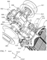
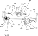
- the electric work vehicle preferably includes a parking assembly (e.g., a locking assembly) 520 which is structured to keep the electric work vehicle stationary when it is not being actively driven by a user, as shown in Figs. 10 , 11 , and 22-24 .
- the parking assembly 520 preferably includes a parking shaft 522 which is able to be actuated in the left-right direction of the electric work vehicle to engage left and right parking pawls 524L and 524R.
- the parking shaft 522 is preferably biased, for example, in the right direction by bias springs 526, and includes two actuating protrusions 5220 and a flange 5222.
- the actuating protrusions 5220 are respectively provided one for each of the left and right parking pawls 524L and 524R.
- the actuating protrusions 5220 include angled engaging surfaces which press the parking pawls 524L and 524R to engage with an outermost gear of the left motor transmission gear 544L and an outermost gear of the right motor transmission gear 544R when the parking shaft 522 is moved, for example, in the right direction of the electric work vehicle.
- the equilibrium state of the parking assembly 520 is preferably a parked position with the left and right parking pawls 524L and 524R engaged with the left motor transmission gear 544L and the right motor transmission gear 544R.
- the left and right parking pawls 524L and 524R are preferably structured to engage with and lock the low speed gear teeth 5440L and 5440R of the left motor transmission gear 544L and the right motor transmission gear 544R simultaneously.
- the parking shaft 522 preferably includes flanges 5222 provided on each terminating end of the parking shaft 522, as shown in Fig. 23 , for example.
- One of the flanges 5222 which may extend to a location outside of the rear housing 12 due to the parking shaft 522 extending though a parking shaft opening 1211 in the rear housing 12, is arranged to be engaged by a linkage 528 through a pulling fork 5282.
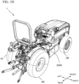
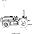
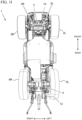
- the linkage 528 is connected to a parking lever 5284 (shown in Figs. 1D , 1F , and 1H ) which is able to be manually actuated by the driver of the electric work vehicle to pull on the parking shaft 522 through the engagement between the flange 5222 and the pulling fork 5282.
- the driver of the electric work vehicle is able to engage and disengage the parking assembly 520 manually through the actuation of the linkage 528.
- the other of the flanges 5222 is arranged to be engaged by a parking actuator 529 which is affixed to a parking actuator retaining portion 1204 defined in the rear housing 12.
- the parking actuator 529 is shown, for example, in Fig. 23 .
- the parking actuator 529 preferably includes a motor (e.g., a servo motor, a stepper motor, etc.) and a rotating cam affixed to an output shaft of the motor, and can be controlled by a controller (e.g., a CPU, a vehicle ECU, a driving controller, etc.).
- the output shaft of the parking actuator 529 preferably intersects an extending direction of the parking shaft 522.
- the parking actuator 529 is preferably located inward of the third electric motor 18 and the fourth electric motor 20 in the left-right direction of the electric work vehicle and is provided on an opposite side of the electric work vehicle from the linkage 528 in the left-right direction of the electric work vehicle, as shown in Fig. 9 , for example.
- the parking actuator 529 is preferably located on a left side of the rear housing 12 and the parking shaft 522 while the linkage 528 is provided on a right side of the rear housing 12 and the parking shaft 522.
- the rotating cam is structured to press on or release pressure from the flange 5222 to thereby actuate the parking shaft 522 in the left-right direction of the electric work vehicle.
- the operation of the parking actuator 529 may be controlled by a driving computer configured or programmed to control the motor, by a button on a dashboard of the electric work vehicle, and by any other desirable manner.
- the engagement and disengagement of the parking assembly 520 may be performed using either or both of the linkage 528 and the parking actuator 529.
- the operation of the parking actuator 529 may be performed without affecting the positioning of the linkage 528 and the parking lever 5284.
- the third gearing 19 and the fourth gearing 21 each preferably include/define both of a high gear transmission path and a lower gear transmission path which may be selectively engaged through the use of a gear shifting assembly 530, as shown in Figs. 10 , 11 , and 22-24 .
- the high gear transmission paths are respectively defined by the high speed gear teeth 5422L and 5442L and the high speed gear teeth 5422R and 5442R.
- the low gear transmission paths are respectively defined by the low speed gear teeth 5420L and 5440L and the low speed gear teeth 5420R and 5440R.
- the gear shifting assembly 530 preferably includes a shifting actuator 532 which is able to be energized to produce pressing forces which move a first shift rod 534 and a second shift rod 535 in opposing vectors within the left-right direction of the electric work vehicle.
- the first shift rod 534 and the second shift rod 535 are connected to respective shift forks 536 which engage with the dog rings 5362 of the left motor driven pinion gear 542L and the right motor driven pinion gear 542R.
- the shift forks 536 are moved laterally outward in the left-right direction of the electric work vehicle, the low speed gear teeth 5420L and 5420R are engaged to be rotated by the third electric motor 18 and the fourth electric motor 20.
- the shift forks 536 are moved laterally inward in the left-right direction of the electric work vehicle, the high speed gear teeth 5422L and 5422R are engaged to be rotated by the third electric motor 18 and the fourth electric motor 20.
- the shifting cam 538 may be an S-shaped cam.
- the shifting actuator 532 is preferably arranged to rotate the shifting cam 538 between the first cam position and the second cam position to change between high range and low range gearing.
- the first shift rod 534 and second shift rod 535 are preferably inwardly biased into the shifting cam 538.
- the first cam position causes the high speed gear teeth 5422L and 5422R to be engaged to be rotated by the third electric motor 18 and the fourth electric motor 20 while the second cam position causes the low speed gear teeth 5420L and 5420R to be engaged to be rotated by the third electric motor 18 and the fourth electric motor 20.
- Position sensors and/or encoders are preferably provided for ends of the first shift rod 534 and the second shift rod 535 and the shifting actuator 532 to determine when the shifting actuator 532 has pushed the first shift rod 534 and the second shift rod 535 far enough to reach the second cam position to thereby engage the low gears.
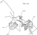
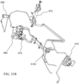
- Figs. 21A and 21B shows a preferred embodiment of a hydraulic assembly of an electric work vehicle according to a preferred embodiment of the present invention.
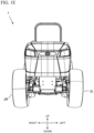
- Control lever(s) 509 and linkage 599 to control the hydraulic assembly is preferably located to a right side of the electric work vehicle, as shown in Figs. 1B , 1D , and 1H .
- the hydraulic assembly preferably includes a hydraulic pump 510 which is driven by the sixth electric motor 24 through a hydraulic motor driven gear 518 which meshes with a hydraulic pump input gear 516 of the hydraulic pump 510.
- the hydraulic pump 510 is preferably affixed to a lower surface of the rear housing 12, as shown in Fig. 8 , for example.
- the hydraulic pump 510 is preferably connected to a hydraulic pump coupling 511 which is connected to hydraulic lines (unlabeled) of the electric work vehicle.
- the hydraulic lines connect the hydraulic pump 510 to a hydraulic filter 512, as shown in Fig. 13A .
- the hydraulic filter 512 preferably includes a filter base 5120 which is further connected to a collection tube 519 which is structured to collect lubricating oil/hydraulic fluid from an inside of the rear housing 12.
- the filter base 5120 is preferably connected to the hydraulic pump 510 through a hydraulic connection tube 514, as shown in Figs. 7 , 8 , and 13A .
- a power steering controller 570, a brake master cylinder 580, and a heat exchanger 590 are also connected to the hydraulic lines of the hydraulic assembly, as shown in Fig. 21B , for example.
- the power steering controller is preferably electrically connected to a control computer of the electric work vehicle, or is mechanically operated in response to a driver's operating of a steering wheel.
- the power steering controller 570 is connected to and controls a steering cylinder 572 which is able to turn the left front wheel 2L and the right front wheel 2R.
- the heat exchanger 590 is structured to remove heat from the lubricating oil/hydraulic fluid which travels through the hydraulic assembly.
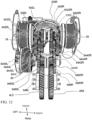
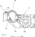
- Fig. 25 shows a cross sectional view of components located/retained within a rear housing 12 of an electric work vehicle according to a preferred embodiment of the present invention.
- the PTO input shaft 504 preferably extends between the gears of the third gearing 19 and the fourth gearing 21 in the left-right direction of the electric work vehicle. Further, the PTO input shaft 504 is preferably located above central axes of the left motor driven pinion gear 542L and the left motor driven pinion gear 542R in the up-down direction of the electric work vehicle.
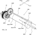
- Fig. 26 shows that a PTO motor gear 2302 is preferably located below the PTO input shaft 504 and the PTO input shaft gear 2300 of the PTO input shaft 504 in the up-down direction of the electric work vehicle.
- a diameter of the PTO input shaft gear 2300 is preferably smaller than a diameter of the fifth electric motor 22.
- the axis of the fifth electric motor 22 is preferably offset from an axis of the PTO input shaft 504 in the left-right direction of the electric work vehicle when the electric work vehicle is viewed from above. Further, and axis of the PTO output shaft 502 is preferably located below the axis of the PTO input shaft 504 in the up-down direction of the electric work vehicle.
- the rear housing 12 preferably contains lubrication oil which, when at rest, includes an oil upper surface.
- the collection tube 519 and the hydraulic filter 512 are located under the oil upper surface in the up-down direction of the electric work vehicle, as shown in Figs. 13A and 25 , for example.
- the oil upper surface is preferably located at or above a lower portion of the PTO motor gear 2302 and at or below a lower portion of the PTO input shaft 504 in the up-down direction of the electric work vehicle.
- the oil upper surface is at least as high as the axis of the PTO output shaft 502 in the up-down direction of the electric work vehicle.
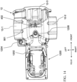
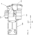
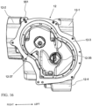
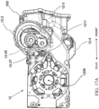
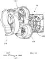
- FIG. 14-20 A preferred embodiment of a rear housing 12 of an electric work vehicle corresponding to the present invention is shown in Figs. 14-20 .
- the rear housing 12 preferably has a T-shape when viewed from above.
- the T-shape is preferably asymmetrical in a left-right direction of the electric work vehicle.
- An upper portion of the rear housing 12 preferably includes a depression portion in which the gear actuator retaining portion 1206 is defined.
- the gear actuator retaining portion 1206 is structured to support the shifting actuator 532.
- the first motor housing portion 12-1 preferably includes a motor shaft passage 12-15 which permits a shaft of the third electric motor 18 to pass into a central portion of the rear housing 12, and a gear shaft support 12-17 which supports the left motor driven pinion gear 542L.
- the second motor housing portion 12-2 preferably includes a motor shaft passage 12-25 which permits a shaft of the fourth electric motor 20 to pass into the central portion of the rear housing 12, and a gear shaft support 12-27 which supports the right motor driven pinion gear 542R.
- the third motor housing portion 12-3 preferably includes a motor shaft passage 12-35 which permits a shaft of the fifth electric motor 22 to pass into the central portion of the rear housing 12 and a PTO input shaft support 12-37 which supports the PTO input shaft gear 2300 and the PTO input shaft 504.
- the fourth motor housing portion 12-4 preferably includes a motor shaft passage 12-45 which permits a shaft of the sixth electric motor 24 to pass into the central portion of the rear housing 12 and a pump support 12-47 which supports the hydraulic pump 510.
- a portion of an upper surface of the rear frame adjacent to the fourth motor housing portion 12-4 preferably includes a parking actuator retaining portion 1204 which is structured to support the parking actuator 529.
- a rear portion of the rear housing 12 preferably defines a gear casing 1200 which houses the third gearing 19 and the fourth gearing 21.
- An upper portion of the gear casing 1200 preferably includes a gear access opening 1202 and a rear portion of the gear casing 1200 preferably includes the PTO opening 1210.
- the rear housing 12 preferably includes at least a first oil path 550 and a second oil path 560 which pass through the rear housing 12 to permit oil to be circulated back into the rear housing 12 through, for example, hydraulic/oil lines.
- the first oil path 550 is preferably provided on a right side of the rear housing 12 adjacent to the second motor housing portion 12-2.
- the first oil path 550 preferably includes a front inlet opening 551, a side inlet opening 552, a first channel 553, and a first outlet opening 554.
- the front inlet opening 551 is preferably defined in a front surface of the rear housing 12 between the second motor housing portion 12-2 and the third motor housing portion 12-3.
- the side inlet opening 552 is preferably defined is a right side surface of the rear housing 12 adjacent to the second motor housing portion 12-2.
- the first channel 553 preferably extends horizontally in the front-rear direction of the electrical vehicle.
- the front inlet opening 551 and the side inlet opening 552 preferably extend in perpendicular directions and are connected to a first channel 553 which extends in a front-rear direction of the electrical vehicle.
- the front inlet opening 551 is preferably connected to an oil return from the brake master cylinder 580 while the side inlet opening 552 is preferably connected to a main oil return line.
- the first outlet opening 554 is preferably provided at a rear end of the first channel 553 and deposits the oil into a central reservoir of the rear housing 12.
- the first outlet opening 554 is preferably located above the right motor driven pinion gear 542R, and most preferably is structured to drop oil onto the low speed gear teeth 5420R.
- the second oil path 560 preferably includes a top inlet opening 561, a second channel 562, and a second outlet 563, as shown in Figs. 14 and 28-31 , for example.
- the second oil path 560 preferably lubricates third and fourth shafts 1802 and 2002 of the third electric motor 18 and the fourth electric motor 20 which are connected to the left and right motor driven pinion gears 542L and 542R.
- the third and fourth shafts 1802 and 2002 are preferably at least partially hollow.
- the top inlet opening 561 is preferably provided on a central portion of an upper surface of the rear housing 12 and is connected to a low pressure oil supply.
- the second channel 562 preferably extends vertically downward from the top inlet opening 561 to a central portion of the rear housing 12.
- the second outlet 563 is provided at an axial bottom of the second channel 562 and directs the oil input into the top inlet opening 561 to components within the rear housing 12.
- the front inlet opening 551, the side inlet opening 552, and the top inlet opening 561 are preferably located forward of the third and fourth shafts 1802 and 2002 of the third electric motor 18 and the fourth electric motor 20 in the front-rear direction of the electric work vehicle.
- the oil output from the first oil path 550 is preferably introduced above the fourth shaft 2002 and oil output from the second oil path 560 is preferably introduced to a location inside of or between the third and fourth shafts 1802 and 2002, as shown in Fig. 31 .
- the rear housing 12 preferably includes a tank breather 400 which allows air to exit from an inside of the rear housing 12 to an outside of the rear housing 12.
- the tank breather 400 preferably includes a first opening 402 and a second opening 404.
- the first opening 402 preferably opens upwards out of an upper surface of the rear housing 12.
- the second opening 404 preferably opens inwards into an inner portion of the rear housing 12, to permit air to flow from the inside of the rear housing 12 into the second opening 404 and then out of the first opening 402.
- the tank breather 400 is preferably located on an opposite side of the rear housing 12 with respect to the first oil path 550 in the left-right direction of the electric work vehicle.
Landscapes
- Engineering & Computer Science (AREA)
- Mechanical Engineering (AREA)
- Transportation (AREA)
- Chemical & Material Sciences (AREA)
- Combustion & Propulsion (AREA)
- General Engineering & Computer Science (AREA)
- Power Engineering (AREA)
- Arrangement Or Mounting Of Propulsion Units For Vehicles (AREA)
- Auxiliary Drives, Propulsion Controls, And Safety Devices (AREA)
- Motor Power Transmission Devices (AREA)
- Braking Arrangements (AREA)
- Gear-Shifting Mechanisms (AREA)
- Connection Of Motors, Electrical Generators, Mechanical Devices, And The Like (AREA)
Applications Claiming Priority (2)
| Application Number | Priority Date | Filing Date | Title |
|---|---|---|---|
| US202363546275P | 2023-10-30 | 2023-10-30 | |
| US18/532,057 US12594828B2 (en) | 2023-10-30 | 2023-12-07 | Electric work vehicle |
Publications (2)
| Publication Number | Publication Date |
|---|---|
| EP4549195A2 true EP4549195A2 (de) | 2025-05-07 |
| EP4549195A3 EP4549195A3 (de) | 2025-05-14 |
Family
ID=93291630
Family Applications (1)
| Application Number | Title | Priority Date | Filing Date |
|---|---|---|---|
| EP24209185.8A Pending EP4549195A3 (de) | 2023-10-30 | 2024-10-28 | Elektrisches arbeitsfahrzeug |
Country Status (3)
| Country | Link |
|---|---|
| US (1) | US12594828B2 (de) |
| EP (1) | EP4549195A3 (de) |
| JP (1) | JP2025090514A (de) |
Family Cites Families (171)
| Publication number | Priority date | Publication date | Assignee | Title |
|---|---|---|---|---|
| US1055619A (en) * | 1912-04-27 | 1913-03-11 | William Dunn | Hydraulic transmission mechanism. |
| US1428236A (en) * | 1921-06-02 | 1922-09-05 | Jonathan L Jones | Automobile lock |
| US1609833A (en) * | 1921-12-12 | 1926-12-07 | Universal Engineering Corp | Locomotive engine |
| US2031399A (en) * | 1934-02-16 | 1936-02-18 | Holice N White | Automobile power take-off mechanism |
| US4034824A (en) * | 1975-12-29 | 1977-07-12 | Harold P. Lucas | Vehicle wheel lock assembly |
| US4233858A (en) * | 1976-12-27 | 1980-11-18 | The Garrett Corporation | Flywheel drive system having a split electromechanical transmission |
| JPS6325421Y2 (de) * | 1980-04-03 | 1988-07-11 | ||
| US4622833A (en) * | 1984-09-10 | 1986-11-18 | Shepherd Richard L | Vehicle wheel lock |
| US4845949A (en) * | 1987-11-18 | 1989-07-11 | Shivvers, Inc. | Parking brake for integrated transmission |
| JP2538356B2 (ja) * | 1989-11-20 | 1996-09-25 | 株式会社神崎高級工機製作所 | 自走式作業車のトランスミツシヨン装置 |
| US5065848A (en) * | 1989-11-27 | 1991-11-19 | Barrett David M | Brake-disc-rotor attacher impeller (intersecting/locker) |
| US5046306A (en) * | 1990-07-23 | 1991-09-10 | General Motors Corporation | Secondary oil system |
| US5113977A (en) * | 1990-12-18 | 1992-05-19 | Strato-Lift, Inc. | Lift truck parking brake |
| US5419406A (en) * | 1991-10-24 | 1995-05-30 | Aisin Aw Co., Ltd. | Drive system for electric car |
| JP3445339B2 (ja) * | 1993-11-25 | 2003-09-08 | 株式会社 神崎高級工機製作所 | 作業車用四輪駆動トランスミッション |
| US5406778A (en) * | 1994-02-03 | 1995-04-18 | Ransomes America Corporation | Electric drive riding greens mower |
| JP3445391B2 (ja) * | 1994-11-11 | 2003-09-08 | 株式会社 神崎高級工機製作所 | トラクタのトランスミッション装置 |
| US5873224A (en) * | 1995-09-07 | 1999-02-23 | Kubota Corporation | Power transmitting structure for a self-propelling vehicle having a working implement |
| US5557977A (en) * | 1995-11-06 | 1996-09-24 | Ford Motor Company | System for powering rotating vehicle accessories using transmission |
| US6048288A (en) * | 1997-11-18 | 2000-04-11 | Toyota Jidosha Kabushiki Kaisha | Power train system for a vehicle and method for operating same |
| US6109009A (en) * | 1998-01-16 | 2000-08-29 | Textron Inc. | Constant speed control for electric greens mower |
| CA2259771C (en) * | 1998-02-19 | 2003-04-01 | Hitachi, Ltd. | Transmission, and vehicle and bicycle using the same |
| GB2343924A (en) * | 1998-11-19 | 2000-05-24 | Ford New Holland Nv | Parking lock for an agricultural implement. |
| US6170615B1 (en) * | 1999-03-29 | 2001-01-09 | Hui-Fen Cheng | Braking device of a three wheel baby car |
| EP1350421B1 (de) * | 2002-04-03 | 2006-06-07 | Kanzaki Kokyukoki MFG. Co., Ltd. | Pump- und Arbeitsfahrzeug |
| US7391129B2 (en) * | 2002-05-31 | 2008-06-24 | Ise Corporation | System and method for powering accessories in a hybrid vehicle |
| US7179188B2 (en) * | 2002-08-02 | 2007-02-20 | Norihiro Ishii | Transmission apparatus for a working vehicle |
| US6860358B1 (en) * | 2002-10-04 | 2005-03-01 | Hydro-Gear Limited Partnership | Utility vehicle having hydrostatic drive |
| JP2004155390A (ja) * | 2002-11-08 | 2004-06-03 | Nissan Motor Co Ltd | 車両用制動装置 |
| US7225617B1 (en) * | 2003-01-13 | 2007-06-05 | Hydro-Gear Limited Partnership | Bypass mechanism for a hydraulic drive apparatus |
| US6953327B1 (en) * | 2003-03-11 | 2005-10-11 | Hydro-Gear Limited Partnership | Dual pump |
| DE10318070C5 (de) * | 2003-04-17 | 2022-06-23 | Volkswagen Ag | Vorrichtung und Verfahren zur Schmierung und Kühlung von Zahnradgetrieben |
| EP1473183B1 (de) * | 2003-04-17 | 2009-01-14 | Kanzaki Kokyukoki MFG. Co., Ltd. | Leistungsteilungs- und Wellenantriebseinrichtung für ein Arbeitsfahrzeug |
| DE10319684A1 (de) * | 2003-05-02 | 2004-12-23 | Zf Friedrichshafen Ag | Verteilerdifferenzial für Kraftfahrzeuge |
| US6964631B2 (en) * | 2004-02-24 | 2005-11-15 | General Motors Corporation | Integrated electric motor-driven oil pump for automatic transmissions in hybrid applications |
| DE102004024086A1 (de) * | 2004-05-14 | 2005-12-08 | Audi Ag | Antriebsvorrichtung für Kraftfahrzeuge |
| JP4208774B2 (ja) * | 2004-06-24 | 2009-01-14 | 株式会社クボタ | 乗用型草刈り機 |
| US7421917B2 (en) * | 2004-06-25 | 2008-09-09 | Kubota Corporation | Tractor with a PTO apparatus |
| US20060059879A1 (en) * | 2004-09-20 | 2006-03-23 | Edmond Brian W | Multifunction electric tractor |
| TWI330218B (en) * | 2004-10-29 | 2010-09-11 | Tai Her Yang | Split serial-parallel hybrid dual-power drive system |
| JP2006321339A (ja) * | 2005-05-18 | 2006-11-30 | Kanzaki Kokyukoki Mfg Co Ltd | 油圧駆動式作業車両の動力伝達機構 |
| FR2898833B1 (fr) * | 2006-03-23 | 2008-12-05 | Conception & Dev Michelin Sa | Liaison au sol pour vehicule |
| JP2007283986A (ja) * | 2006-04-19 | 2007-11-01 | Kanzaki Kokyukoki Mfg Co Ltd | 油圧式車軸駆動装置 |
| JP2008157161A (ja) * | 2006-12-26 | 2008-07-10 | Kanzaki Kokyukoki Mfg Co Ltd | マルチポンプユニットおよびマルチポンプユニット付車両 |
| JP4179388B1 (ja) * | 2007-05-24 | 2008-11-12 | トヨタ自動車株式会社 | 車両用制御装置 |
| JP4311754B2 (ja) * | 2007-06-21 | 2009-08-12 | 三菱電機株式会社 | 車両用駆動装置 |
| US7713157B2 (en) * | 2007-07-11 | 2010-05-11 | Eaton Corporation | Planetary gear controlled alternator |
| US8818588B2 (en) * | 2007-07-12 | 2014-08-26 | Odyne Systems, Llc | Parallel hybrid drive system utilizing power take off connection as transfer for a secondary energy source |
| US9878616B2 (en) * | 2007-07-12 | 2018-01-30 | Power Technology Holdings Llc | Hybrid vehicle drive system and method using split shaft power take off |
| US8978798B2 (en) * | 2007-10-12 | 2015-03-17 | Odyne Systems, Llc | Hybrid vehicle drive system and method and idle reduction system and method |
| US7726275B2 (en) * | 2007-07-12 | 2010-06-01 | Ford Global Technologies, Llc | System and method for powering a mechanically driven accessory component in an automotive vehicle |
| US20120207620A1 (en) * | 2007-07-12 | 2012-08-16 | Odyne Systems, LLC. | Hybrid vehicle drive system and method and idle reduction system and method |
| US7578116B1 (en) * | 2007-08-10 | 2009-08-25 | Richard D. Meyer | Battery-operated riding rotary mower |
| EP3109091B1 (de) * | 2007-09-11 | 2021-11-10 | Hydro-Gear Limited Partnership | Steuerungssysteme und -verfahren für nutzfahrzeuge mit elektrischem antrieb |
| US8808124B2 (en) * | 2008-04-15 | 2014-08-19 | GM Global Technology Operations LLC | Belt alternator starter systems for hybrid vehicles |
| JP4707072B2 (ja) * | 2008-05-23 | 2011-06-22 | 本田技研工業株式会社 | 車両用動力伝達装置 |
| US9549504B2 (en) * | 2008-06-06 | 2017-01-24 | Kanzaki Kokyukoki Mfg. Co., Ltd. | Transaxle system for vehicle |
| US8055399B2 (en) * | 2008-10-23 | 2011-11-08 | Hydro-Gear Limited Partnership | Control systems and methods for electric motors of utility vehicles |
| WO2010104189A1 (en) * | 2009-03-09 | 2010-09-16 | Nissan Motor Co., Ltd. | Parking lock device |
| US8701806B2 (en) * | 2009-03-18 | 2014-04-22 | Kanzaki Kokyukoki Mfg. Co., Ltd. | Electric transaxle unit |
| US8511216B2 (en) * | 2009-03-30 | 2013-08-20 | Kanzaki Kokyukoki Mfg. Co., Ltd. | Hydraulic actuator unit |
| CN102470744B (zh) * | 2009-07-31 | 2015-06-03 | 本田技研工业株式会社 | 车辆 |
| WO2011036959A1 (ja) * | 2009-09-25 | 2011-03-31 | アイシン・エィ・ダブリュ株式会社 | 駆動装置 |
| EP2332760B1 (de) * | 2009-12-09 | 2012-09-12 | Kanzaki Kokyukoki Mfg. Co., Ltd. | Elektrische Getriebeeinheit |
| CN102666169A (zh) * | 2010-01-18 | 2012-09-12 | 日立建机株式会社 | 作业用车辆的驱动控制装置 |
| US20110190083A1 (en) * | 2010-02-02 | 2011-08-04 | ALTe | Accessory drive system for a vehicle |
| JP5168598B2 (ja) * | 2010-03-31 | 2013-03-21 | アイシン・エィ・ダブリュ株式会社 | ハイブリッド駆動装置 |
| JP5365880B2 (ja) * | 2010-06-08 | 2013-12-11 | アイシン・エィ・ダブリュ株式会社 | 車両用駆動装置 |
| US8649925B2 (en) * | 2010-08-30 | 2014-02-11 | Ford Global Technologies, Llc | Method and system for controlling operation of an electric oil pump in a hybrid electric vehicle (HEV) |
| US8322482B2 (en) * | 2010-09-27 | 2012-12-04 | Deere & Company | Tractor ground positioning system |
| US8689759B2 (en) * | 2010-10-01 | 2014-04-08 | GM Global Technology Operations LLC | Dual drive pump system using an engine starter motor |
| US8888637B2 (en) * | 2010-12-10 | 2014-11-18 | Means Industries, Inc. | Vehicle drive system including a transmission |
| US8616310B2 (en) * | 2011-01-14 | 2013-12-31 | Gilbert T. Lopez | Apparatus for farming, gardening and landscaping |
| JP5297473B2 (ja) * | 2011-02-04 | 2013-09-25 | アイシン・エィ・ダブリュ株式会社 | 車両用駆動装置 |
| US8905885B2 (en) * | 2011-02-04 | 2014-12-09 | Aisin Aw Co., Ltd. | Vehicle drive device |
| JP2012187025A (ja) * | 2011-03-09 | 2012-10-04 | Kubota Corp | 乗用作業車 |
| CN103109112B (zh) * | 2011-04-13 | 2015-10-14 | 日产自动车株式会社 | 车辆用轮内马达单元的润滑控制装置 |
| CA2838592C (en) * | 2011-06-07 | 2016-10-25 | Honda Motor Co., Ltd. | Vehicle driving device |
| WO2013009324A1 (en) * | 2011-07-14 | 2013-01-17 | Husqvarna Ab | Riding lawn mower including battery powered cutting system |
| WO2013011562A1 (ja) * | 2011-07-19 | 2013-01-24 | トヨタ自動車株式会社 | ハイブリッド車両用動力伝達装置の潤滑装置 |
| JP2013053737A (ja) * | 2011-09-06 | 2013-03-21 | Honda Motor Co Ltd | 遊星歯車機構の支持構造 |
| US9163724B1 (en) * | 2011-10-24 | 2015-10-20 | Hydro-Gear Limited Partnership | Transaxle having dual brake system |
| US9371842B1 (en) * | 2011-11-17 | 2016-06-21 | Hydro-Gear Limited Partnership | Hydraulic motor having a dual brake system |
| JP5699227B2 (ja) * | 2011-12-01 | 2015-04-08 | 本田技研工業株式会社 | 動力伝達装置 |
| US8784246B2 (en) * | 2011-12-14 | 2014-07-22 | Caterpillar Inc. | Series drivetrain with CVT output |
| WO2013093986A1 (ja) * | 2011-12-24 | 2013-06-27 | 川崎重工業株式会社 | 電動車両 |
| JP5826042B2 (ja) * | 2012-01-12 | 2015-12-02 | 株式会社クボタ | 電動作業車 |
| JP5885534B2 (ja) * | 2012-02-21 | 2016-03-15 | 本田技研工業株式会社 | 制御システム |
| EP2639128B1 (de) * | 2012-03-13 | 2023-09-06 | Kanzaki Kokyukoki Mfg. Co., Ltd. | Nutzfahrzeug |
| JP2015514624A (ja) * | 2012-03-29 | 2015-05-21 | イートン コーポレーションEaton Corporation | 可変速度式ハイブリッド電気スーパーチャージャーアセンブリを用いた電気エネルギの生成 |
| US9500197B2 (en) * | 2012-05-18 | 2016-11-22 | Gm Global Technology Operations, Llc | Pump assembly with multiple gear ratios |
| WO2014018503A1 (en) * | 2012-07-25 | 2014-01-30 | Fisker Automotive, Inc. | All wheel drive system for hybrid vehicle |
| DE102013013623B4 (de) * | 2012-08-29 | 2022-06-30 | Kanzaki Kokyukoki Mfg. Co., Ltd. | Motorsteuersystem für ein mit elektrischem Motor angetriebenes Fahrzeug |
| JP6192919B2 (ja) * | 2012-11-02 | 2017-09-06 | Ntn株式会社 | インホイールモータ駆動装置 |
| US9033074B1 (en) * | 2012-11-19 | 2015-05-19 | Chris Gates | Coupler with movable shaft |
| JP5790630B2 (ja) * | 2012-12-05 | 2015-10-07 | トヨタ自動車株式会社 | 潤滑油供給構造 |
| JP5741563B2 (ja) * | 2012-12-06 | 2015-07-01 | トヨタ自動車株式会社 | 動力伝達装置 |
| US9114798B1 (en) * | 2012-12-12 | 2015-08-25 | Hydro-Gear Limited Partnership | Electric actuator for drive apparatus |
| US8939240B2 (en) * | 2013-03-01 | 2015-01-27 | Paccar Inc | Engine accessory drive system |
| US9872438B2 (en) * | 2013-03-15 | 2018-01-23 | Mtd Products Inc | Battery-electric and internal-combustion engine assist hybrid propulsion and implement drive work systems |
| JP6070972B2 (ja) * | 2013-03-15 | 2017-02-01 | デーナ、オータモウティヴ、システィムズ、グループ、エルエルシー | 変速機用パーキングロック機構 |
| US9487086B2 (en) * | 2013-04-02 | 2016-11-08 | Parker-Hannifin Corporation | Auxiliary modules mounted on a vehicle |
| SE538232C2 (sv) * | 2013-05-08 | 2016-04-12 | BAE Systems Hägglunds Aktiebolag | Drivenhet för bandgående fordon och fordon försett med drivenhet |
| SE540219C2 (sv) * | 2013-05-21 | 2018-05-02 | Scania Cv Ab | Kraftuttag, fordon med ett sådant kraftuttag och ett mellanstycke för ett sådant kraftuttag |
| FR3008038B1 (fr) * | 2013-07-02 | 2016-12-02 | Technoboost | Groupe motopropulseur pour un vehicule hybride hydraulique, comprenant une machine electrique |
| JP5705928B2 (ja) * | 2013-08-08 | 2015-04-22 | 株式会社小松製作所 | ホイールローダ |
| WO2015074074A1 (en) * | 2013-11-18 | 2015-05-21 | Odyne Systems, Llc | Hybrid vehicle drive system and method using split shaft power take off |
| JP6182438B2 (ja) * | 2013-11-26 | 2017-08-16 | アイシン・エィ・ダブリュ株式会社 | 車両用駆動伝達装置 |
| DE102013017976A1 (de) * | 2013-11-29 | 2015-06-03 | Fte Automotive Gmbh | Elektromotorisch angetriebene Flüssigkeitspumpe, insbesondere zur Zwangsschmierung eines Schaltgetriebes für Kraftfahrzeuge |
| MY188847A (en) * | 2013-12-02 | 2022-01-09 | Honda Motor Co Ltd | Vehicle |
| JP6265726B2 (ja) * | 2013-12-16 | 2018-01-24 | 株式会社小松製作所 | 作業車両及び作業車両の制御方法 |
| JP6364194B2 (ja) * | 2014-01-29 | 2018-07-25 | 株式会社小松製作所 | 作業車両及びその制御方法 |
| GB2523765B (en) * | 2014-03-04 | 2016-09-28 | Johnston Sweepers Ltd | Powertrain for a road cleaning vehicle |
| US9499199B1 (en) * | 2014-04-23 | 2016-11-22 | Hydro-Gear Limited Partnership | Hybrid vehicle |
| MY167373A (en) * | 2014-06-10 | 2018-08-16 | Honda Motor Co Ltd | Power plant |
| US9156348B1 (en) * | 2014-07-17 | 2015-10-13 | GM Global Technology Operations LLC | Two axis electric drive |
| US10781891B2 (en) * | 2014-09-16 | 2020-09-22 | Means Industries, Inc. | Drive system including a transmission and magnetic coupling device for an electric vehicle |
| US10781920B2 (en) * | 2014-09-16 | 2020-09-22 | Means Industries, Inc. | Drive systems including transmissions and magnetic coupling devices for electric and hybrid electric vehicles |
| US9145054B1 (en) * | 2014-10-20 | 2015-09-29 | Power Solutions International, Inc. | Modular power take-off assembly |
| US20160145833A1 (en) * | 2014-11-21 | 2016-05-26 | Caterpillar Global Mining Llc | System and method for controlling power in machine having hydraulic devices |
| US10300786B2 (en) * | 2014-12-19 | 2019-05-28 | Polaris Industries Inc. | Utility vehicle |
| JP2016130115A (ja) * | 2015-01-15 | 2016-07-21 | トヨタ自動車株式会社 | ハイブリッド車の駆動制御装置 |
| US11701959B2 (en) * | 2015-02-17 | 2023-07-18 | Oshkosh Corporation | Inline electromechanical variable transmission system |
| JP6914247B2 (ja) * | 2015-05-01 | 2021-08-04 | ブラックバーン エナジー インコーポレイテッド | 補助発電のための方法およびシステム |
| US10358040B1 (en) * | 2015-06-01 | 2019-07-23 | Hydro-Gear Limited Partnership | Drive assembly and system for utility vehicle |
| US10106027B1 (en) * | 2015-06-01 | 2018-10-23 | Hydro-Gear Limited Partnership | Generator/cooling assembly and system for utility vehicle |
| US10563761B2 (en) * | 2015-08-07 | 2020-02-18 | Yanmar Co., Ltd. | Work vehicle |
| JP6314947B2 (ja) * | 2015-10-02 | 2018-04-25 | トヨタ自動車株式会社 | 動力伝達装置の冷却構造 |
| CN107303814A (zh) * | 2016-04-18 | 2017-10-31 | 深圳市沃特玛电池有限公司 | 一种电动车动力轮系总成 |
| JP6696857B2 (ja) * | 2016-08-12 | 2020-05-20 | トヨタ自動車株式会社 | 車両用歯車装置の潤滑装置 |
| US10099552B2 (en) * | 2016-09-30 | 2018-10-16 | Deere & Company | Hydraulic-electric drive arrangement for work vehicles |
| JP6477656B2 (ja) * | 2016-10-14 | 2019-03-06 | トヨタ自動車株式会社 | 動力伝達装置の油路構造 |
| JP6423403B2 (ja) * | 2016-10-14 | 2018-11-14 | トヨタ自動車株式会社 | 動力伝達装置の油路構造 |
| JP2018062314A (ja) * | 2016-10-14 | 2018-04-19 | Ntn株式会社 | インホイールモータ駆動装置 |
| US20180328487A1 (en) * | 2016-12-01 | 2018-11-15 | Kanzaki Kokyukoki Mfg Co, Ltd. | Shift-drum speed change operation mechanism |
| US11746876B2 (en) * | 2017-03-23 | 2023-09-05 | Cascade Drives Ab | Compound planet gear arrangement and gear wheel arrangement |
| JP6545217B2 (ja) * | 2017-03-24 | 2019-07-17 | 本田技研工業株式会社 | 動力伝達装置の潤滑流体供給構造 |
| JP6680263B2 (ja) * | 2017-05-19 | 2020-04-15 | トヨタ自動車株式会社 | ハイブリッド車両の駆動装置 |
| JP6809393B2 (ja) * | 2017-06-20 | 2021-01-06 | トヨタ自動車株式会社 | 車両用動力伝達装置の潤滑装置 |
| US10781910B2 (en) * | 2017-08-03 | 2020-09-22 | Power Technology Holdings Llc | PTO lubrication system for hybrid vehicles |
| JP6338003B1 (ja) * | 2017-09-27 | 2018-06-06 | トヨタ自動車株式会社 | 電気自動車 |
| JP6811698B2 (ja) * | 2017-11-21 | 2021-01-13 | 株式会社クボタ | 作業車及び作業車管理システム |
| CN110739804B (zh) * | 2018-07-18 | 2022-04-12 | 株式会社爱信 | 旋转电机的冷却构造和车辆用驱动装置 |
| JP7107565B2 (ja) * | 2018-10-22 | 2022-07-27 | 株式会社 神崎高級工機製作所 | 移動体駆動ユニット及び移動体 |
| JP6996474B2 (ja) * | 2018-10-31 | 2022-01-17 | トヨタ自動車株式会社 | 動力伝達装置の潤滑装置 |
| US10948070B2 (en) * | 2018-11-13 | 2021-03-16 | Deere & Company | Electric machine lubrication system |
| KR102663984B1 (ko) * | 2018-11-23 | 2024-05-07 | 현대자동차 주식회사 | 전기 자동차의 다단 변속기용 기어 시프팅 장치 |
| JP7111006B2 (ja) * | 2019-01-25 | 2022-08-02 | トヨタ自動車株式会社 | 車両用動力伝達装置 |
| JP7052746B2 (ja) * | 2019-01-25 | 2022-04-12 | トヨタ自動車株式会社 | 車両用動力伝達装置 |
| US11084369B2 (en) * | 2019-02-26 | 2021-08-10 | Deere & Company | Hybrid transmission module for work vehicles |
| JP7172762B2 (ja) * | 2019-03-13 | 2022-11-16 | トヨタ自動車株式会社 | 車両用油供給装置の制御装置 |
| US10690234B1 (en) * | 2019-03-14 | 2020-06-23 | Proterra Inc. | Electric vehicle powertrain |
| JP7151632B2 (ja) * | 2019-06-11 | 2022-10-12 | トヨタ自動車株式会社 | ハイブリッド車両 |
| JP7246264B2 (ja) * | 2019-06-24 | 2023-03-27 | 株式会社クボタ | 電動作業車 |
| JP7224245B2 (ja) * | 2019-06-24 | 2023-02-17 | 株式会社クボタ | 電動作業車 |
| US10989297B2 (en) * | 2019-07-19 | 2021-04-27 | Ford Global Technologies, Llc | Electric powertrain with sun bearing |
| JP7132191B2 (ja) * | 2019-08-08 | 2022-09-06 | ヤンマーパワーテクノロジー株式会社 | 作業車両用の自動走行システム |
| US10981024B1 (en) * | 2019-10-11 | 2021-04-20 | Oshkosh Corporation | Hybrid fire fighting vehicle |
| EP4077014A1 (de) * | 2019-12-19 | 2022-10-26 | AGCO International GmbH | Verfahren zum betrieb eines landwirtschaftlichen fahrzeugs und getriebeanordnung für ein landwirtschaftliches fahrzeug |
| US12024027B2 (en) * | 2020-07-27 | 2024-07-02 | Kinetics Drive Solutions, Inc. | Electro-mechanical cross steer drive device for a vehicle |
| JP7671157B2 (ja) * | 2021-03-08 | 2025-05-01 | ニデック株式会社 | 駆動装置 |
| DE102021116297B4 (de) * | 2021-06-24 | 2023-01-26 | Bayerische Motoren Werke Aktiengesellschaft | Kraftfahrzeug mit einem Koppelgetriebe und mit einer Parksperrvorrichtung |
| KR102923051B1 (ko) * | 2021-07-14 | 2026-02-04 | 현대자동차 주식회사 | 전기 자동차용 동력 전달 장치 |
| JP2023034634A (ja) * | 2021-08-31 | 2023-03-13 | 株式会社 神崎高級工機製作所 | 作業車両 |
| DE202021105282U1 (de) * | 2021-09-30 | 2021-10-18 | Thaddäus Baier | Elektroantriebsstruktur für eine Arbeitsmaschine |
| DE102022101279B4 (de) * | 2022-01-20 | 2025-06-12 | Bayerische Motoren Werke Aktiengesellschaft | Kraftfahrzeug mit einem Koppelgetriebe und mit einer funktionsgesicherten Parksperrvorrichtung |
| WO2023161917A1 (en) * | 2022-02-24 | 2023-08-31 | Ree Automotive Ltd. | Systems for locking rotatable shaft |
| US11754169B1 (en) * | 2022-07-07 | 2023-09-12 | Ford Global Technologies, Llc | Lubrication and cooling oil distribution system for a vehicle transaxle |
| CN119585131A (zh) * | 2022-07-12 | 2025-03-07 | 电力推进技术有限责任公司 | 紧凑型电动轴组件 |
| JP2024096596A (ja) * | 2023-01-04 | 2024-07-17 | 株式会社クボタ | 電動作業車 |
| JP2024168371A (ja) * | 2023-05-23 | 2024-12-05 | トヨタ自動車株式会社 | 電動車両の駆動装置 |
-
2023
- 2023-12-07 US US18/532,057 patent/US12594828B2/en active Active
-
2024
- 2024-10-23 JP JP2024186342A patent/JP2025090514A/ja active Pending
- 2024-10-28 EP EP24209185.8A patent/EP4549195A3/de active Pending
Also Published As
| Publication number | Publication date |
|---|---|
| US20250135875A1 (en) | 2025-05-01 |
| US12594828B2 (en) | 2026-04-07 |
| EP4549195A3 (de) | 2025-05-14 |
| JP2025090514A (ja) | 2025-06-17 |
Similar Documents
| Publication | Publication Date | Title |
|---|---|---|
| EP4549193A1 (de) | Elektrisches arbeitsfahrzeug | |
| EP4549195A2 (de) | Elektrisches arbeitsfahrzeug | |
| EP4570548A1 (de) | Elektrisches arbeitsfahrzeug | |
| EP4552880A1 (de) | Elektrisches arbeitsfahrzeug | |
| EP4552879A1 (de) | Elektrisches arbeitsfahrzeug | |
| EP4556274A1 (de) | Elektrisches arbeitsfahrzeug | |
| EP4574496A1 (de) | Elektrisches arbeitsfahrzeug | |
| EP4549214A1 (de) | Elektrisches arbeitsfahrzeug | |
| EP4549213A1 (de) | Elektrisches arbeitsfahrzeug | |
| EP4556276A1 (de) | Elektrisches arbeitsfahrzeug | |
| EP4549666A1 (de) | Elektrisches arbeitsfahrzeug | |
| EP4549210A1 (de) | Elektrisches arbeitsfahrzeug | |
| EP4549194A1 (de) | Elektrisches arbeitsfahrzeug | |
| EP4549196A2 (de) | Elektrisches arbeitsfahrzeug | |
| US12617258B2 (en) | Electric work vehicle | |
| US12358574B2 (en) | Electric work vehicle | |
| US20250133993A1 (en) | Electric work vehicle | |
| EP4549212A1 (de) | Elektrisches arbeitsfahrzeug |
Legal Events
| Date | Code | Title | Description |
|---|---|---|---|
| PUAI | Public reference made under article 153(3) epc to a published international application that has entered the european phase |
Free format text: ORIGINAL CODE: 0009012 |
|
| STAA | Information on the status of an ep patent application or granted ep patent |
Free format text: STATUS: THE APPLICATION HAS BEEN PUBLISHED |
|
| PUAL | Search report despatched |
Free format text: ORIGINAL CODE: 0009013 |
|
| AK | Designated contracting states |
Kind code of ref document: A2 Designated state(s): AL AT BE BG CH CY CZ DE DK EE ES FI FR GB GR HR HU IE IS IT LI LT LU LV MC ME MK MT NL NO PL PT RO RS SE SI SK SM TR |
|
| AK | Designated contracting states |
Kind code of ref document: A3 Designated state(s): AL AT BE BG CH CY CZ DE DK EE ES FI FR GB GR HR HU IE IS IT LI LT LU LV MC ME MK MT NL NO PL PT RO RS SE SI SK SM TR |
|
| RIC1 | Information provided on ipc code assigned before grant |
Ipc: B60K 17/04 20060101ALI20250407BHEP Ipc: B60K 7/00 20060101ALI20250407BHEP Ipc: B60K 1/02 20060101AFI20250407BHEP |
|
| STAA | Information on the status of an ep patent application or granted ep patent |
Free format text: STATUS: REQUEST FOR EXAMINATION WAS MADE |
|
| 17P | Request for examination filed |
Effective date: 20251110 |