EP4549210A1 - Elektrisches arbeitsfahrzeug - Google Patents
Elektrisches arbeitsfahrzeug Download PDFInfo
- Publication number
- EP4549210A1 EP4549210A1 EP24207251.0A EP24207251A EP4549210A1 EP 4549210 A1 EP4549210 A1 EP 4549210A1 EP 24207251 A EP24207251 A EP 24207251A EP 4549210 A1 EP4549210 A1 EP 4549210A1
- Authority
- EP
- European Patent Office
- Prior art keywords
- motor
- work vehicle
- electric work
- electric
- gear
- Prior art date
- Legal status (The legal status is an assumption and is not a legal conclusion. Google has not performed a legal analysis and makes no representation as to the accuracy of the status listed.)
- Pending
Links
Images












Classifications
-
- A—HUMAN NECESSITIES
- A01—AGRICULTURE; FORESTRY; ANIMAL HUSBANDRY; HUNTING; TRAPPING; FISHING
- A01D—HARVESTING; MOWING
- A01D69/00—Driving mechanisms or parts thereof for harvesters or mowers
- A01D69/002—Driving mechanisms or parts thereof for harvesters or mowers driven by power take-off
-
- B—PERFORMING OPERATIONS; TRANSPORTING
- B60—VEHICLES IN GENERAL
- B60K—ARRANGEMENT OR MOUNTING OF PROPULSION UNITS OR OF TRANSMISSIONS IN VEHICLES; ARRANGEMENT OR MOUNTING OF PLURAL DIVERSE PRIME-MOVERS IN VEHICLES; AUXILIARY DRIVES FOR VEHICLES; INSTRUMENTATION OR DASHBOARDS FOR VEHICLES; ARRANGEMENTS IN CONNECTION WITH COOLING, AIR INTAKE, GAS EXHAUST OR FUEL SUPPLY OF PROPULSION UNITS IN VEHICLES
- B60K17/00—Arrangement or mounting of transmissions in vehicles
- B60K17/34—Arrangement or mounting of transmissions in vehicles for driving both front and rear wheels, e.g. four wheel drive vehicles
- B60K17/356—Arrangement or mounting of transmissions in vehicles for driving both front and rear wheels, e.g. four wheel drive vehicles having fluid or electric motor, for driving one or more wheels
-
- A—HUMAN NECESSITIES
- A01—AGRICULTURE; FORESTRY; ANIMAL HUSBANDRY; HUNTING; TRAPPING; FISHING
- A01D—HARVESTING; MOWING
- A01D69/00—Driving mechanisms or parts thereof for harvesters or mowers
- A01D69/02—Driving mechanisms or parts thereof for harvesters or mowers electric
-
- A—HUMAN NECESSITIES
- A01—AGRICULTURE; FORESTRY; ANIMAL HUSBANDRY; HUNTING; TRAPPING; FISHING
- A01D—HARVESTING; MOWING
- A01D69/00—Driving mechanisms or parts thereof for harvesters or mowers
- A01D69/06—Gearings
-
- B—PERFORMING OPERATIONS; TRANSPORTING
- B60—VEHICLES IN GENERAL
- B60K—ARRANGEMENT OR MOUNTING OF PROPULSION UNITS OR OF TRANSMISSIONS IN VEHICLES; ARRANGEMENT OR MOUNTING OF PLURAL DIVERSE PRIME-MOVERS IN VEHICLES; AUXILIARY DRIVES FOR VEHICLES; INSTRUMENTATION OR DASHBOARDS FOR VEHICLES; ARRANGEMENTS IN CONNECTION WITH COOLING, AIR INTAKE, GAS EXHAUST OR FUEL SUPPLY OF PROPULSION UNITS IN VEHICLES
- B60K17/00—Arrangement or mounting of transmissions in vehicles
- B60K17/04—Arrangement or mounting of transmissions in vehicles characterised by arrangement, location or kind of gearing
- B60K17/043—Transmission unit disposed in on near the vehicle wheel, or between the differential gear unit and the wheel
-
- B—PERFORMING OPERATIONS; TRANSPORTING
- B60—VEHICLES IN GENERAL
- B60K—ARRANGEMENT OR MOUNTING OF PROPULSION UNITS OR OF TRANSMISSIONS IN VEHICLES; ARRANGEMENT OR MOUNTING OF PLURAL DIVERSE PRIME-MOVERS IN VEHICLES; AUXILIARY DRIVES FOR VEHICLES; INSTRUMENTATION OR DASHBOARDS FOR VEHICLES; ARRANGEMENTS IN CONNECTION WITH COOLING, AIR INTAKE, GAS EXHAUST OR FUEL SUPPLY OF PROPULSION UNITS IN VEHICLES
- B60K7/00—Disposition of motor in, or adjacent to, traction wheel
- B60K7/0007—Disposition of motor in, or adjacent to, traction wheel the motor being electric
-
- B—PERFORMING OPERATIONS; TRANSPORTING
- B60—VEHICLES IN GENERAL
- B60L—PROPULSION OF ELECTRICALLY-PROPELLED VEHICLES; SUPPLYING ELECTRIC POWER FOR AUXILIARY EQUIPMENT OF ELECTRICALLY-PROPELLED VEHICLES; ELECTRODYNAMIC BRAKE SYSTEMS FOR VEHICLES IN GENERAL; MAGNETIC SUSPENSION OR LEVITATION FOR VEHICLES; MONITORING OPERATING VARIABLES OF ELECTRICALLY-PROPELLED VEHICLES; ELECTRIC SAFETY DEVICES FOR ELECTRICALLY-PROPELLED VEHICLES
- B60L1/00—Supplying electric power to auxiliary equipment of vehicles
- B60L1/003—Supplying electric power to auxiliary equipment of vehicles to auxiliary motors, e.g. for pumps, compressors
-
- B—PERFORMING OPERATIONS; TRANSPORTING
- B60—VEHICLES IN GENERAL
- B60L—PROPULSION OF ELECTRICALLY-PROPELLED VEHICLES; SUPPLYING ELECTRIC POWER FOR AUXILIARY EQUIPMENT OF ELECTRICALLY-PROPELLED VEHICLES; ELECTRODYNAMIC BRAKE SYSTEMS FOR VEHICLES IN GENERAL; MAGNETIC SUSPENSION OR LEVITATION FOR VEHICLES; MONITORING OPERATING VARIABLES OF ELECTRICALLY-PROPELLED VEHICLES; ELECTRIC SAFETY DEVICES FOR ELECTRICALLY-PROPELLED VEHICLES
- B60L50/00—Electric propulsion with power supplied within the vehicle
- B60L50/50—Electric propulsion with power supplied within the vehicle using propulsion power supplied by batteries or fuel cells
- B60L50/51—Electric propulsion with power supplied within the vehicle using propulsion power supplied by batteries or fuel cells characterised by AC-motors
-
- B—PERFORMING OPERATIONS; TRANSPORTING
- B60—VEHICLES IN GENERAL
- B60L—PROPULSION OF ELECTRICALLY-PROPELLED VEHICLES; SUPPLYING ELECTRIC POWER FOR AUXILIARY EQUIPMENT OF ELECTRICALLY-PROPELLED VEHICLES; ELECTRODYNAMIC BRAKE SYSTEMS FOR VEHICLES IN GENERAL; MAGNETIC SUSPENSION OR LEVITATION FOR VEHICLES; MONITORING OPERATING VARIABLES OF ELECTRICALLY-PROPELLED VEHICLES; ELECTRIC SAFETY DEVICES FOR ELECTRICALLY-PROPELLED VEHICLES
- B60L50/00—Electric propulsion with power supplied within the vehicle
- B60L50/50—Electric propulsion with power supplied within the vehicle using propulsion power supplied by batteries or fuel cells
- B60L50/60—Electric propulsion with power supplied within the vehicle using propulsion power supplied by batteries or fuel cells using power supplied by batteries
- B60L50/64—Constructional details of batteries specially adapted for electric vehicles
-
- B—PERFORMING OPERATIONS; TRANSPORTING
- B60—VEHICLES IN GENERAL
- B60L—PROPULSION OF ELECTRICALLY-PROPELLED VEHICLES; SUPPLYING ELECTRIC POWER FOR AUXILIARY EQUIPMENT OF ELECTRICALLY-PROPELLED VEHICLES; ELECTRODYNAMIC BRAKE SYSTEMS FOR VEHICLES IN GENERAL; MAGNETIC SUSPENSION OR LEVITATION FOR VEHICLES; MONITORING OPERATING VARIABLES OF ELECTRICALLY-PROPELLED VEHICLES; ELECTRIC SAFETY DEVICES FOR ELECTRICALLY-PROPELLED VEHICLES
- B60L50/00—Electric propulsion with power supplied within the vehicle
- B60L50/50—Electric propulsion with power supplied within the vehicle using propulsion power supplied by batteries or fuel cells
- B60L50/60—Electric propulsion with power supplied within the vehicle using propulsion power supplied by batteries or fuel cells using power supplied by batteries
- B60L50/66—Arrangements of batteries
-
- B—PERFORMING OPERATIONS; TRANSPORTING
- B60—VEHICLES IN GENERAL
- B60L—PROPULSION OF ELECTRICALLY-PROPELLED VEHICLES; SUPPLYING ELECTRIC POWER FOR AUXILIARY EQUIPMENT OF ELECTRICALLY-PROPELLED VEHICLES; ELECTRODYNAMIC BRAKE SYSTEMS FOR VEHICLES IN GENERAL; MAGNETIC SUSPENSION OR LEVITATION FOR VEHICLES; MONITORING OPERATING VARIABLES OF ELECTRICALLY-PROPELLED VEHICLES; ELECTRIC SAFETY DEVICES FOR ELECTRICALLY-PROPELLED VEHICLES
- B60L58/00—Methods or circuit arrangements for monitoring or controlling batteries or fuel cells, specially adapted for electric vehicles
- B60L58/10—Methods or circuit arrangements for monitoring or controlling batteries or fuel cells, specially adapted for electric vehicles for monitoring or controlling batteries
- B60L58/18—Methods or circuit arrangements for monitoring or controlling batteries or fuel cells, specially adapted for electric vehicles for monitoring or controlling batteries of two or more battery modules
- B60L58/21—Methods or circuit arrangements for monitoring or controlling batteries or fuel cells, specially adapted for electric vehicles for monitoring or controlling batteries of two or more battery modules having the same nominal voltage
-
- F—MECHANICAL ENGINEERING; LIGHTING; HEATING; WEAPONS; BLASTING
- F16—ENGINEERING ELEMENTS AND UNITS; GENERAL MEASURES FOR PRODUCING AND MAINTAINING EFFECTIVE FUNCTIONING OF MACHINES OR INSTALLATIONS; THERMAL INSULATION IN GENERAL
- F16H—GEARING
- F16H1/00—Toothed gearings for conveying rotary motion
- F16H1/02—Toothed gearings for conveying rotary motion without gears having orbital motion
- F16H1/20—Toothed gearings for conveying rotary motion without gears having orbital motion involving more than two intermeshing members
-
- F—MECHANICAL ENGINEERING; LIGHTING; HEATING; WEAPONS; BLASTING
- F16—ENGINEERING ELEMENTS AND UNITS; GENERAL MEASURES FOR PRODUCING AND MAINTAINING EFFECTIVE FUNCTIONING OF MACHINES OR INSTALLATIONS; THERMAL INSULATION IN GENERAL
- F16H—GEARING
- F16H57/00—General details of gearing
- F16H57/04—Features relating to lubrication or cooling or heating
- F16H57/0434—Features relating to lubrication or cooling or heating relating to lubrication supply, e.g. pumps; Pressure control
-
- F—MECHANICAL ENGINEERING; LIGHTING; HEATING; WEAPONS; BLASTING
- F16—ENGINEERING ELEMENTS AND UNITS; GENERAL MEASURES FOR PRODUCING AND MAINTAINING EFFECTIVE FUNCTIONING OF MACHINES OR INSTALLATIONS; THERMAL INSULATION IN GENERAL
- F16H—GEARING
- F16H57/00—General details of gearing
- F16H57/04—Features relating to lubrication or cooling or heating
- F16H57/0457—Splash lubrication
-
- B—PERFORMING OPERATIONS; TRANSPORTING
- B60—VEHICLES IN GENERAL
- B60K—ARRANGEMENT OR MOUNTING OF PROPULSION UNITS OR OF TRANSMISSIONS IN VEHICLES; ARRANGEMENT OR MOUNTING OF PLURAL DIVERSE PRIME-MOVERS IN VEHICLES; AUXILIARY DRIVES FOR VEHICLES; INSTRUMENTATION OR DASHBOARDS FOR VEHICLES; ARRANGEMENTS IN CONNECTION WITH COOLING, AIR INTAKE, GAS EXHAUST OR FUEL SUPPLY OF PROPULSION UNITS IN VEHICLES
- B60K1/00—Arrangement or mounting of electrical propulsion units
- B60K1/04—Arrangement or mounting of electrical propulsion units of the electric storage means for propulsion
- B60K2001/0405—Arrangement or mounting of electrical propulsion units of the electric storage means for propulsion characterised by their position
- B60K2001/0416—Arrangement in the rear part of the vehicle
-
- B—PERFORMING OPERATIONS; TRANSPORTING
- B60—VEHICLES IN GENERAL
- B60K—ARRANGEMENT OR MOUNTING OF PROPULSION UNITS OR OF TRANSMISSIONS IN VEHICLES; ARRANGEMENT OR MOUNTING OF PLURAL DIVERSE PRIME-MOVERS IN VEHICLES; AUXILIARY DRIVES FOR VEHICLES; INSTRUMENTATION OR DASHBOARDS FOR VEHICLES; ARRANGEMENTS IN CONNECTION WITH COOLING, AIR INTAKE, GAS EXHAUST OR FUEL SUPPLY OF PROPULSION UNITS IN VEHICLES
- B60K7/00—Disposition of motor in, or adjacent to, traction wheel
- B60K2007/0061—Disposition of motor in, or adjacent to, traction wheel the motor axle being parallel to the wheel axle
-
- B—PERFORMING OPERATIONS; TRANSPORTING
- B60—VEHICLES IN GENERAL
- B60L—PROPULSION OF ELECTRICALLY-PROPELLED VEHICLES; SUPPLYING ELECTRIC POWER FOR AUXILIARY EQUIPMENT OF ELECTRICALLY-PROPELLED VEHICLES; ELECTRODYNAMIC BRAKE SYSTEMS FOR VEHICLES IN GENERAL; MAGNETIC SUSPENSION OR LEVITATION FOR VEHICLES; MONITORING OPERATING VARIABLES OF ELECTRICALLY-PROPELLED VEHICLES; ELECTRIC SAFETY DEVICES FOR ELECTRICALLY-PROPELLED VEHICLES
- B60L2200/00—Type of vehicles
- B60L2200/40—Working vehicles
-
- B—PERFORMING OPERATIONS; TRANSPORTING
- B60—VEHICLES IN GENERAL
- B60L—PROPULSION OF ELECTRICALLY-PROPELLED VEHICLES; SUPPLYING ELECTRIC POWER FOR AUXILIARY EQUIPMENT OF ELECTRICALLY-PROPELLED VEHICLES; ELECTRODYNAMIC BRAKE SYSTEMS FOR VEHICLES IN GENERAL; MAGNETIC SUSPENSION OR LEVITATION FOR VEHICLES; MONITORING OPERATING VARIABLES OF ELECTRICALLY-PROPELLED VEHICLES; ELECTRIC SAFETY DEVICES FOR ELECTRICALLY-PROPELLED VEHICLES
- B60L2210/00—Converter types
- B60L2210/40—DC to AC converters
-
- B—PERFORMING OPERATIONS; TRANSPORTING
- B60—VEHICLES IN GENERAL
- B60L—PROPULSION OF ELECTRICALLY-PROPELLED VEHICLES; SUPPLYING ELECTRIC POWER FOR AUXILIARY EQUIPMENT OF ELECTRICALLY-PROPELLED VEHICLES; ELECTRODYNAMIC BRAKE SYSTEMS FOR VEHICLES IN GENERAL; MAGNETIC SUSPENSION OR LEVITATION FOR VEHICLES; MONITORING OPERATING VARIABLES OF ELECTRICALLY-PROPELLED VEHICLES; ELECTRIC SAFETY DEVICES FOR ELECTRICALLY-PROPELLED VEHICLES
- B60L2220/00—Electrical machine types; Structures or applications thereof
- B60L2220/40—Electrical machine applications
- B60L2220/42—Electrical machine applications with use of more than one motor
-
- B—PERFORMING OPERATIONS; TRANSPORTING
- B60—VEHICLES IN GENERAL
- B60L—PROPULSION OF ELECTRICALLY-PROPELLED VEHICLES; SUPPLYING ELECTRIC POWER FOR AUXILIARY EQUIPMENT OF ELECTRICALLY-PROPELLED VEHICLES; ELECTRODYNAMIC BRAKE SYSTEMS FOR VEHICLES IN GENERAL; MAGNETIC SUSPENSION OR LEVITATION FOR VEHICLES; MONITORING OPERATING VARIABLES OF ELECTRICALLY-PROPELLED VEHICLES; ELECTRIC SAFETY DEVICES FOR ELECTRICALLY-PROPELLED VEHICLES
- B60L2220/00—Electrical machine types; Structures or applications thereof
- B60L2220/40—Electrical machine applications
- B60L2220/46—Wheel motors, i.e. motor connected to only one wheel
-
- B—PERFORMING OPERATIONS; TRANSPORTING
- B60—VEHICLES IN GENERAL
- B60L—PROPULSION OF ELECTRICALLY-PROPELLED VEHICLES; SUPPLYING ELECTRIC POWER FOR AUXILIARY EQUIPMENT OF ELECTRICALLY-PROPELLED VEHICLES; ELECTRODYNAMIC BRAKE SYSTEMS FOR VEHICLES IN GENERAL; MAGNETIC SUSPENSION OR LEVITATION FOR VEHICLES; MONITORING OPERATING VARIABLES OF ELECTRICALLY-PROPELLED VEHICLES; ELECTRIC SAFETY DEVICES FOR ELECTRICALLY-PROPELLED VEHICLES
- B60L2240/00—Control parameters of input or output; Target parameters
- B60L2240/10—Vehicle control parameters
- B60L2240/36—Temperature of vehicle components or parts
-
- B—PERFORMING OPERATIONS; TRANSPORTING
- B60—VEHICLES IN GENERAL
- B60L—PROPULSION OF ELECTRICALLY-PROPELLED VEHICLES; SUPPLYING ELECTRIC POWER FOR AUXILIARY EQUIPMENT OF ELECTRICALLY-PROPELLED VEHICLES; ELECTRODYNAMIC BRAKE SYSTEMS FOR VEHICLES IN GENERAL; MAGNETIC SUSPENSION OR LEVITATION FOR VEHICLES; MONITORING OPERATING VARIABLES OF ELECTRICALLY-PROPELLED VEHICLES; ELECTRIC SAFETY DEVICES FOR ELECTRICALLY-PROPELLED VEHICLES
- B60L2260/00—Operating Modes
- B60L2260/20—Drive modes; Transition between modes
- B60L2260/28—Four wheel or all wheel drive
-
- B—PERFORMING OPERATIONS; TRANSPORTING
- B60—VEHICLES IN GENERAL
- B60Y—INDEXING SCHEME RELATING TO ASPECTS CROSS-CUTTING VEHICLE TECHNOLOGY
- B60Y2200/00—Type of vehicle
- B60Y2200/20—Off-Road Vehicles
- B60Y2200/22—Agricultural vehicles
-
- F—MECHANICAL ENGINEERING; LIGHTING; HEATING; WEAPONS; BLASTING
- F16—ENGINEERING ELEMENTS AND UNITS; GENERAL MEASURES FOR PRODUCING AND MAINTAINING EFFECTIVE FUNCTIONING OF MACHINES OR INSTALLATIONS; THERMAL INSULATION IN GENERAL
- F16H—GEARING
- F16H57/00—General details of gearing
- F16H57/02—Gearboxes; Mounting gearing therein
- F16H2057/02034—Gearboxes combined or connected with electric machines
Definitions
- the present invention is directed to an electric work vehicle (EV) such as an electric tractor.
- EV electric work vehicle
- Electric work vehicles are becoming more prevalent as the industry moves from internal combustion engines towards fully electrically powered motors running on battery systems.
- Preferred embodiments of the present invention provide an electric work vehicle.
- a preferred embodiment of an electric work vehicle of the present invention includes a rear housing, a gear casing, a first motor to drive a first rear wheel, the first motor being supported by the rear housing, a second motor to drive a second rear wheel, the second motor being supported by the rear housing, a third motor to drive a first electric work vehicle component other than a wheel, the third motor being supported by the rear housing, and a fourth motor to drive a second electric work vehicle component other than a wheel, the fourth motor being supported by the rear housing.
- the rear housing is wider than the gear casing in a left-right direction of the electric work vehicle.
- the rear housing houses the first motor, the second motor, the third motor, and the fourth motor.
- the gear casing houses first gears located between the first motor and the first rear wheel and second gears located between the second motor and the second rear wheel.
- the third motor may be located closer to one of the first motor or the second motor and farther from another one of the first motor or the second motor.
- the first rear wheel and the second rear wheel may be connected to respective rear wheel hubs which may be mounted to the gear casing.
- the first gearing and the second gearing may each extend from the rear housing into the gear casing.
- the first electric work component may include a Power Take-Off (PTO), and the third motor may be connected to the PTO via a PTO input shaft which may extend from the front side of the rear housing out through an opening in a rear side of the rear housing.
- the PTO input shaft may be connected to the third motor through at least one PTO gear, and the PTO input shaft may be located above an output shaft of the PTO in the up-down direction of the electric work vehicle.
- Electric work vehicles may be a tractor or other agricultural vehicle, but any desirable type of electric work vehicle is applicable to and usable with preferred embodiments of the present invention.
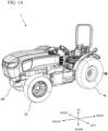
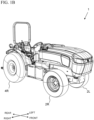
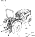
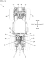
- Fig. 1A to 1I show an electric work vehicle 1 according to a preferred embodiment of the present invention.
- Fig. 1A and 1B show perspective views from left and right front ends of the vehicle 1, respectively.
- Fig. 1C shows an isometric view from a left rear end of the vehicle 1.
- Fig. 1D shows an isometric view from a right rear end of the vehicle 1.
- Fig. 1E shows a front view of the vehicle 1.
- Fig. 1F and 1G are side views of the vehicle 1.
- Fig. 1H and 1I are top and bottom views of the vehicle 1, respectively.
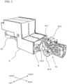
- the vehicle 1 includes an intermediate frame 6, a battery housing 8 attached to a front portion of the intermediate frame 6, a front frame 10 attached to the battery housing 8, and a rear housing 12 attached a rear portion of the intermediate frame 6, as shown in Fig. 2 , for example.
- a front axle 3 connected to the left front wheel 2L and a right front wheel 2R is connected to and supports the front frame 10
- a rear axle 5 connected to the left rear wheel 4L and the right rear wheel 4R is connected to and supported by the rear housing 12, as shown in Fig. 11 , for example.
- the front axle 3 includes a left axle housing 3L and a right axle housing 3R, as shown in Fig. 1I .
- the left axle housing 3L houses a first electric motor 14 (a left-front-wheel electric motor) that is connected to a first gearing 15 to drive the left front wheel 2L
- the right axle housing 3R houses a second electric motor 16 (a right-front-wheel electric motor) that is connected to a second gearing 17 to drive the right front wheel 2R.
- the first electric motor 14, the second electric motor 16, the first gearing 15, and the second gearing 17 are shown, for example, in Fig. 1J in which the left axle housing 3L and the right axle housing 3R have been removed for illustrative purposes.
- the rear housing 12 includes a first motor housing portion 12-1 to house a third electric motor 18 (a left-rear-wheel electric motor) that is connected to a third gearing 19 to drive the left rear wheel 4L, and a second motor housing portion 12-2 to house a fourth electric motor 20 (a right-rear-wheel electric motor) that is connected to a fourth gearing 21 to drive the right rear wheel 4R.
- a third electric motor 18 a left-rear-wheel electric motor
- a second motor housing portion 12-2 to house a fourth electric motor 20 (a right-rear-wheel electric motor) that is connected to a fourth gearing 21 to drive the right rear wheel 4R.
- the rear housing 12 also includes a third motor housing portion 12-3 to house a fifth electric motor 22 that is connected to a fifth gearing 23 to drive a first electric work vehicle component (e.g., a power take-off (PTO)), and a fourth motor housing portion 12-4 to house a sixth electric motor 24 that is connected to a sixth gearing 25 to drive a second electric work vehicle component (e.g., a hydraulic system), as shown in Figs. 1J and 2 , for example.
- the third electric motor 18, the fourth electric motor 20, the fifth electric motor 22, and the sixth electric motor 24 are shown, for example, in Fig. 1J in which elements including the rear housing 12 have been removed for illustrative purposes. In the bottom view of Fig. 11 , the sixth electric motor 24 overlaps the third electric motor 18.
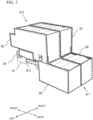
- the battery housing 8 includes a first battery housing portion 26, a second battery housing portion 28, a third battery housing portion 30, a fourth battery housing portion 32, and a fifth battery housing portion 34, each of which is shown in Fig. 3 using dashed lines.
- the first battery housing portion 26 and the second battery housing portion 28 are adjacent to each other in a width direction of the vehicle
- the third battery housing portion 30 and the fourth battery housing portion 32 are adjacent to each other in a width direction of the vehicle.
- a width of each of the first battery housing portion 26, the second battery housing portion 28, the third battery housing portion 30, the fourth battery housing portion 32, and the fifth battery housing portion 34 width direction of the vehicle is equal or substantially equal.
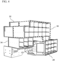
- Figs. 4 , 5A, and 5B show the battery housing 8 with the battery housing portion covers removed for illustrative purposes.
- the first battery housing portion 26 and the second battery housing portion 28 are included in a first battery housing section 8-1 (a rear battery housing section), the third battery housing portion 30 and the fourth battery housing portion 32 are included in a second battery housing section 8-2 (a forward-upper battery housing section), and the fifth battery housing portion 34 is included in a third battery housing section 8-3 (a forward-lower battery housing section), as shown in Fig. 3 , for example.
- a width of the first battery housing section 8-1 is equal or substantially equal to a width of the second battery housing section 8-2
- a width of the third battery housing section 8-3 is less than a width of the first battery housing section 8-1 and a width of the second battery housing section 8-2.
- each of the first battery housing portion 26, the second battery housing portion 28, the third battery housing portion 30, the fourth battery housing portion 32, and the fifth battery housing portion 34 includes a plurality of battery housing module compartments, which are each to receive a battery module.
- each of the third battery housing portion 30 and the fourth battery housing portion 32 includes more battery housing module compartments than each of the first battery housing portion 26 and the second battery housing portion 28.
- the fifth battery housing portion 34 includes less battery housing module compartments than each of the first battery housing portion 26 and the second battery housing portion 28.
- one or more inverters 13 are connected to, attached on, or supported by the battery housing 8.
- the one or more inverters 13 can include a first inverter 13-1, a second inverter 13-2, a third inverter 13-3, a fourth inverter 13-4, a fifth inverter 13-5, a sixth inverter 13-6, and a seventh inverter 13-7.
- the first inverter 13-1, the third inverter 13-3, the sixth inverter 13-6, and the seventh inverter 13-7 are located on a left side of the battery housing 8.
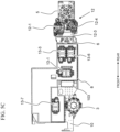
- the second inverter 13-2, the fourth inverter 13-4, and the fifth inverter 13-5 are located on a right side of the battery housing 8. More specifically, as shown in Figs. 5C and 5D , the seventh inverter 13-7 can be attached to a left side cover of the fifth battery housing portion 34, each of the first inverter 13-1, the third inverter 13-3, and the sixth inverter 13-6 can be attached to a left side cover of the second battery housing portion 28, and each of the second inverter 13-2, the fourth inverter 13-4, and the fifth inverter 13-5 can be attached to a right side cover of the first battery housing portion 26.
- the total number of the inverters 13 is not limited, and the inverters 13 may be provided at other locations within the vehicle 1.
- the first inverter 13-1 can provide electric power to the first electric motor 14, the second inverter 13-2 can provide electric power to the second electric motor 16, the third inverter 13-3 can provide electric power to the third electric motor 18, the fourth inverter 13-4 can provide electric power to the fourth electric motor 20, the fifth inverter 13-5 can provide electric power to the fifth electric motor 22, and the sixth inverter 13-6 can provide electric power to the sixth electric motor 24.
- the seventh inverter 13-7 can provide electric power to other components of the electric work vehicle 1, for example, a cooling structure such as a radiator/condenser fan.
- a front portion of the rear housing 12 is connected to a rear portion of the intermediate frame 6 and a front portion of the intermediate frame 6 is connected to a rear portion of the battery housing 8.
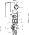
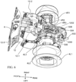
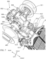
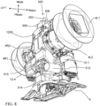
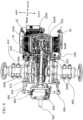
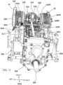
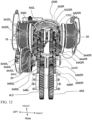
- Figs. 6-8 show components which are affixed to and housed within the rear housing 12.
- the components affixed to and housed within the rear housing 12 preferably include, for example, a left hub and casing 4L2, a right hub and casing 4R2, the third through sixth electric motors 18, 20, 22, and 24, the third through sixth gearings 19, 21, 23, and 25, a Power Take-Off (PTO) 500, a hydraulic pump 510, a parking assembly 520, a gear shifting assembly 530, and a rear driving gear assembly 540 including components from and interacting with the third through sixth gearings 19, 21, 23, and 25.
- PTO Power Take-Off
- the left hub and casing 4L2 and the right hub and casing 4R2 are respectively connected to a left rear rim 4L1 which supports the left rear wheel 4L and a right rear rim 4R1 which supports the right rear wheel 4R.
- Inner ends of the left hub and casing 4L2 and the right hub and casing 4R2 are respectively connected to left and right sides of a gear casing 1200 of the rear housing 12.
- the gear casing 1200 preferably includes wheel hub access openings 1208 which permit driveshafts to extend from an inside of the gear casing 1200 into the left hub and casing 4L2 and the right hub and casing 4R2.
- the third electric motor 18 and the fourth electric motor 20 are structured to respectively drive the left rear wheel 4L and the right rear wheel 4R.
- the third electric motor 18 and the fourth electric motor 20 are respectively housed/located in a first motor housing portion 12-1 and a second motor housing portion 12-2 adjacent to a front of the rear housing 12.
- the sixth electric motor 24 which is preferably structured to drive a hydraulic pump 510 (discussed later), is located in a fourth motor housing portion 12-4 which is below one of the third electric motor 18 and the fourth electric motor 20 in an up-down direction of the electrical vehicle such that the sixth electric motor 24 is located closer to the one of the third electric motor 18 and the fourth electric motor 20 than it is to the other one of the third electric motor 18 and the fourth electric motor 20.
- the fifth electric motor 22 is structured to drive the PTO 500.
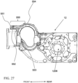
- the fifth electric motor 22 is preferably mounted in the third motor housing portion 12-3 located at the front of the rear housing 12. As shown, for example, in Fig. 26 , the fifth electric motor 22 transmits rotational energy to the PTO 500 through the fifth gearing 23.
- the fifth gearing 23 preferably includes a PTO motor gear 2302 which is driven by an output shaft of the fifth electric motor 22 and a PTO input shaft gear 2300 which is driven by the PTO motor gear 2302.
- the fifth electric motor 22 is preferably larger and has a greater torque output and power rating than each of the third electric motor 18, the fourth electric motor 20, and the sixth electric motor 24.
- a central axis of the fifth electric motor 22 is preferably located below central axes of the third electric motor 18 and the fourth electric motor 20 as shown, for example, in Figs. 10-12 .
- the central axis of the fifth electric motor 22 preferably extends perpendicularly or substantially perpendicularly to the central axes of the third electric motor 18 and the fourth electric motor 20 as shown, for example, in Figs. 10-13C .
- a central axis of the sixth electric motor 24 preferably extends in parallel or substantially in parallel with the central axes of the third electric motor 18 and the fourth electric motor 20 as shown, for example, in Figs. 10-12 .
- the central axes of the third electric motor 18 and the fourth electric motor 20 are preferably aligned and colinear with one another as shown, for example, in Figs. 10-12 .
- Central axes of the fifth electric motor 22 and the sixth electric motor 24 are preferably located below the third electric motor 18 and the fourth electric motor 20 in the up-down direction of the electrical vehicle as shown, for example, in Figs. 10-12 .
- the PTO 500 preferably includes a PTO input shaft 504 which is fixed to the PTO input shaft gear 2300.
- the PTO input shaft 504 extends in a front-back direction of the electric work vehicle and engages with a PTO output shaft 502 which is supported by a PTO housing 508.
- the PTO input shaft 504 preferably includes a rotation transferring portion 5041 which engages with a rotation transferring portion 5021 of the PTO output shaft 502.
- the rotation transferring portions 5021 and 5041 are preferably gear-shaped portions (the gear teeth of the rotation transferring portions 5021 and 5041 are omitted from Figs.
- the PTO output shaft 502 is structured to be able to engage with and operate standard PTO agricultural accessories.
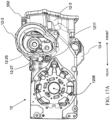
- the PTO housing 508 is preferably connected to a rear end of the gear casing 1200, with a PTO opening 1210 being defined in the gear casing 1200 to permit the PTO input shaft 504 to extend from the PTO input shaft gear 2300 to an outside of the gear casing 1200, as shown in Fig. 17B .
- the PTO housing 508 is preferably supported by the rear end of the gear casing 1200 and PTO supporting brackets 506 provided on left and right sides of the electrical vehicle, as shown in Fig. 9 .
- the PTO supporting brackets 506 preferably contact both a portion of the PTO housing 508 and portions of respective ones of the left hub and casing 4L2 and the right hub and casing 4R2.
- the third gearing 19 preferably includes a left motor driven pinion gear 542L, a left motor transmission gear 544L, a left driving ratio gear 546L, and a left wheel driving gear 4L3.
- the fourth gearing 21 preferably includes a right motor driven pinion gear 542R, a right motor transmission gear 544R, a right driving ratio gear 546R, and a right wheel driving gear 4R3.
- the left motor driven pinion gear 542L and the right motor driven pinion gear 542R are preferably directly connected to rotating shafts of the third electric motor 18 and the fourth electric motor 20, respectively.
- the left motor driven pinion gear 542L includes different diameter portions including low speed gear teeth 5420L and high speed gear teeth 5422L which are provided on two ends of, and selectively engageable by, a dog clutch through a dog ring 5362 which is controlled by a shift fork 536 (discussed in detail later).
- the right motor driven pinion gear 542R includes different diameter portions including low speed gear teeth 5420R and high speed gear teeth 5422R which are provided on two ends of dog rings 5362L and 5362R controlled by respective shift forks 536L and 536R.
- the left motor transmission gear 544L and the right motor transmission gear 544R are arranged to respectively engage with the left motor driven pinion gear 542L and the right motor driven pinion gear 542R.
- the left motor transmission gear 544L preferably includes different diameter portions with low speed gear teeth 5440L which engage with the low speed gear teeth 5420L, high speed gear teeth 5442L which engage with the high speed gear teeth 5422L, and driving teeth 5444L which engage with the left driving ratio gear 546L.
- the left driving ratio gear 546L and the right driving ratio gear 546R are arranged to respectively engage with the left wheel driving gear 4L3 and the right wheel driving gear 4R3.
- the left driving ratio gear 546L includes different diameter portions with input teeth 5460L which engage with the driving teeth 5444L and output teeth 5462L which engage with the left wheel driving gear 4L3.
- the right driving ratio gear 546R includes different diameter portions with input teeth 5460R which engage with the driving teeth 5444R and output teeth 5462R which engage with the right wheel driving gear 4R3.
- the left wheel driving gear 4L3 and the right wheel driving gear 4R3 are preferably located such that their central axes are between (i) the third electric motor 18 and the fourth electric motor 20 and (ii) the sixth electric motor 24 in the up-down direction of the electric work vehicle.
- a laterally outermost portion of the third gearing 19 is located inward from the third electric motor 18 in the left-right direction of the electric work vehicle
- a laterally outermost portion of the fourth gearing 21 is located inward from the fourth electric motor 20 in the left-right direction of the electric work vehicle.
- At least highest portions of the third gearing 19 and the fourth gearing 21 are preferably located above an axis of the fifth electric motor 22, or the central axis of the fifth electric motor 22, in the up-down direction of the electric work vehicle.
- Preferably all portions of the third gearing 19, the fourth gearing 21, the fifth gearing 23, and the sixth gearing 25 are located between the third electric motor 18 and the fourth electric motor 20 in the left-right direction of the electric work vehicle.
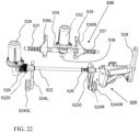
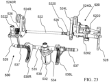
- the electric work vehicle preferably includes a parking assembly (e.g., a locking assembly) 520 which is structured to keep the electric work vehicle stationary when it is not being actively driven by a user, as shown in Figs. 10 , 11 , and 22-24 .
- the parking assembly 520 preferably includes a parking shaft 522 which is able to be actuated in the left-right direction of the electric work vehicle to engage left and right parking pawls 524L and 524R.
- the left and right parking pawls 524L and 524R are able to contact portions of the third gearing 19 and the fourth gearing 21 to thereby fix the rotational positions of the third gearing 19 and the fourth gearing 21 such that the third electric motor 18 and the fourth electric motor 20 are not able to drive the left rear wheel 4L and the right rear wheel 4R. Further, when the left and right parking pawls 524L and 524R fix the rotational positions of the third gearing 19 and the fourth gearing 21, the wheels of the electric work vehicle are prevented from rotating in response to externally applied forces (e.g., a slope or incline of the ground on which the electric work vehicle may be located, pushing/pulling force applied by another vehicle, pushing/pulling force applied by humans or animals, etc.).
- externally applied forces e.g., a slope or incline of the ground on which the electric work vehicle may be located, pushing/pulling force applied by another vehicle, pushing/pulling force applied by humans or animals, etc.
- the left and right parking pawls 524L and 524R are preferably rotationally supported by left and right parking pawl rotary supports 5240L and 5240R which allow the left and right parking pawls 524L and 524R to be selectively tilted towards and away from the left motor transmission gear 544L and the right motor transmission gear 544R in response to lateral movement by the parking shaft 522.
- the parking pawls 524L and 524R are preferably provide a biasing force which acts on the left and right parking pawls 524L and 524R to pull them away from the left motor transmission gear 544L and the right motor transmission gear 544R.
- the parking shaft 522 is preferably biased, for example, in the right direction by bias springs 526, and includes two actuating protrusions 5220 and a flange 5222.
- the actuating protrusions 5220 are respectively provided one for each of the left and right parking pawls 524L and 524R.
- the actuating protrusions 5220 include angled engaging surfaces which press the parking pawls 524L and 524R to engage with an outermost gear of the left motor transmission gear 544L and an outermost gear of the right motor transmission gear 544R when the parking shaft 522 is moved, for example, in the right direction of the electric work vehicle.
- the equilibrium state of the parking assembly 520 is preferably a parked position with the left and right parking pawls 524L and 524R engaged with the left motor transmission gear 544L and the right motor transmission gear 544R.
- the left and right parking pawls 524L and 524R are preferably structured to engage with and lock the low speed gear teeth 5440L and 5440R of the left motor transmission gear 544L and the right motor transmission gear 544R simultaneously.
- the parking shaft 522 preferably includes flanges 5222 provided on each terminating end of the parking shaft 522, as shown in Fig. 23 , for example.
- One of the flanges 5222 which may extend to a location outside of the rear housing 12 due to the parking shaft 522 extending though a parking shaft opening 1211 in the rear housing 12, is arranged to be engaged by a linkage 528 through a pulling fork 5282.
- the linkage 528 is connected to a parking lever 5284 (shown in Figs. 1D , 1F , and 1H ) which is able to be manually actuated by the driver of the electric work vehicle to pull on the parking shaft 522 through the engagement between the flange 5222 and the pulling fork 5282.
- the driver of the electric work vehicle is able to engage and disengage the parking assembly 520 manually through the actuation of the linkage 528.
- the other of the flanges 5222 is arranged to be engaged by a parking actuator 529 which is affixed to a parking actuator retaining portion 1204 defined in the rear housing 12.
- the parking actuator 529 is shown, for example, in Fig. 23 .
- the parking actuator 529 preferably includes a motor (e.g., a servo motor, a stepper motor, etc.) and a rotating cam affixed to an output shaft of the motor, and can be controlled by a controller (e.g., a CPU, a vehicle ECU, a driving controller, etc.).
- the output shaft of the parking actuator 529 preferably intersects an extending direction of the parking shaft 522.
- the parking actuator 529 is preferably located inward of the third electric motor 18 and the fourth electric motor 20 in the left-right direction of the electric work vehicle and is provided on an opposite side of the electric work vehicle from the linkage 528 in the left-right direction of the electric work vehicle, as shown in Fig. 9 , for example.
- the parking actuator 529 is preferably located on a left side of the rear housing 12 and the parking shaft 522 while the linkage 528 is provided on a right side of the rear housing 12 and the parking shaft 522.
- the rotating cam is structured to press on or release pressure from the flange 5222 to thereby actuate the parking shaft 522 in the left-right direction of the electric work vehicle.
- the operation of the parking actuator 529 may be controlled by a driving computer configured or programmed to control the motor, by a button on a dashboard of the electric work vehicle, and by any other desirable manner.
- the engagement and disengagement of the parking assembly 520 may be performed using either or both of the linkage 528 and the parking actuator 529.
- the operation of the parking actuator 529 may be performed without affecting the positioning of the linkage 528 and the parking lever 5284.
- the third gearing 19 and the fourth gearing 21 each preferably include/define both of a high gear transmission path and a lower gear transmission path which may be selectively engaged through the use of a gear shifting assembly 530, as shown in Figs. 10 , 11 , and 22-24 .
- the high gear transmission paths are respectively defined by the high speed gear teeth 5422L and 5442L and the high speed gear teeth 5422R and 5442R.
- the low gear transmission paths are respectively defined by the low speed gear teeth 5420L and 5440L and the low speed gear teeth 5420R and 5440R.
- the gear shifting assembly 530 preferably includes a shifting actuator 532 which is able to be energized to produce pressing forces which move a first shift rod 534 and a second shift rod 535 in opposing vectors within the left-right direction of the electric work vehicle.
- the first shift rod 534 and the second shift rod 535 are connected to respective shift forks 536 which engage with the dog rings 5362 of the left motor driven pinion gear 542L and the right motor driven pinion gear 542R.
- the shift forks 536 are moved laterally outward in the left-right direction of the electric work vehicle, the low speed gear teeth 5420L and 5420R are engaged to be rotated by the third electric motor 18 and the fourth electric motor 20.
- the shift forks 536 are moved laterally inward in the left-right direction of the electric work vehicle, the high speed gear teeth 5422L and 5422R are engaged to be rotated by the third electric motor 18 and the fourth electric motor 20.
- the first shift rod 534 and a second shift rod 535 are preferably biased inward towards a center of the electric work vehicle in the left-right direction of the electric work vehicle by shift rod biasing springs 537.
- the shifting actuator 532 is preferably mounted to a gear actuator retaining portion 1206 of the rear housing 12 such that a portion of the shifting actuator 532 is located outside of the rear housing 12.
- the shifting actuator 532 preferably includes a shifting cam 538 which moves from a first cam position to a second cam position to applies the pressing forces that move the first shift rod 534 and the second shift rod 535.
- the shifting cam 538 preferably has point symmetry about a rotational axis of the shifting cam 538.
- the shifting cam 538 may be an S-shaped cam.
- the shifting actuator 532 is preferably arranged to rotate the shifting cam 538 between the first cam position and the second cam position to change between high range and low range gearing.
- the first shift rod 534 and second shift rod 535 are preferably inwardly biased into the shifting cam 538.
- the first cam position causes the high speed gear teeth 5422L and 5422R to be engaged to be rotated by the third electric motor 18 and the fourth electric motor 20 while the second cam position causes the low speed gear teeth 5420L and 5420R to be engaged to be rotated by the third electric motor 18 and the fourth electric motor 20.
- Position sensors and/or encoders are preferably provided for ends of the first shift rod 534 and the second shift rod 535 and the shifting actuator 532 to determine when the shifting actuator 532 has pushed the first shift rod 534 and the second shift rod 535 far enough to reach the second cam position to thereby engage the low gears.
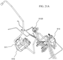
- Figs. 21A and 21B shows a preferred embodiment of a hydraulic assembly of an electric work vehicle according to a preferred embodiment of the present invention.
- Control lever(s) 509 and linkage 599 to control the hydraulic assembly is preferably located to a right side of the electric work vehicle, as shown in Figs. 1B , 1D , and 1H .
- the hydraulic assembly preferably includes a hydraulic pump 510 which is driven by the sixth electric motor 24 through a hydraulic motor driven gear 518 which meshes with a hydraulic pump input gear 516 of the hydraulic pump 510.
- the hydraulic pump 510 is preferably affixed to a lower surface of the rear housing 12, as shown in Fig. 8 , for example.
- the hydraulic pump 510 is preferably connected to a hydraulic pump coupling 511 which is connected to hydraulic lines (unlabeled) of the electric work vehicle.
- the hydraulic lines connect the hydraulic pump 510 to a hydraulic filter 512, as shown in Fig. 13A .
- the hydraulic filter 512 preferably includes a filter base 5120 which is further connected to a collection tube 519 which is structured to collect lubricating oil/hydraulic fluid from an inside of the rear housing 12.
- the filter base 5120 is preferably connected to the hydraulic pump 510 through a hydraulic connection tube 514, as shown in Figs. 7 , 8 , and 13A .
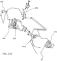
- a power steering controller 570, a brake master cylinder 580, and a heat exchanger 590 are also connected to the hydraulic lines of the hydraulic assembly, as shown in Fig. 21B , for example.
- the power steering controller is preferably electrically connected to a control computer of the electric work vehicle, or is mechanically operated in response to a driver's operating of a steering wheel.
- the power steering controller 570 is connected to and controls a steering cylinder 572 which is able to turn the left front wheel 2L and the right front wheel 2R.
- the heat exchanger 590 is structured to remove heat from the lubricating oil/hydraulic fluid which travels through the hydraulic assembly.
- Fig. 25 shows a cross sectional view of components located/retained within a rear housing 12 of an electric work vehicle according to a preferred embodiment of the present invention.
- the PTO input shaft 504 preferably extends between the gears of the third gearing 19 and the fourth gearing 21 in the left-right direction of the electric work vehicle. Further, the PTO input shaft 504 is preferably located above central axes of the left motor driven pinion gear 542L and the left motor driven pinion gear 542R in the up-down direction of the electric work vehicle.
- Fig. 26 shows that a PTO motor gear 2302 is preferably located below the PTO input shaft 504 and the PTO input shaft gear 2300 of the PTO input shaft 504 in the up-down direction of the electric work vehicle.
- a diameter of the PTO input shaft gear 2300 is preferably smaller than a diameter of the fifth electric motor 22.
- the axis of the fifth electric motor 22 is preferably offset from an axis of the PTO input shaft 504 in the left-right direction of the electric work vehicle when the electric work vehicle is viewed from above. Further, and axis of the PTO output shaft 502 is preferably located below the axis of the PTO input shaft 504 in the up-down direction of the electric work vehicle.
- the rear housing 12 preferably contains lubrication oil which, when at rest, includes an oil upper surface.
- the collection tube 519 and the hydraulic filter 512 are located under the oil upper surface in the up-down direction of the electric work vehicle, as shown in Figs. 13A and 25 , for example.
- the oil upper surface is preferably located at or above a lower portion of the PTO motor gear 2302 and at or below a lower portion of the PTO input shaft 504 in the up-down direction of the electric work vehicle.
- the oil upper surface is at least as high as the axis of the PTO output shaft 502 in the up-down direction of the electric work vehicle.
- the lubrication oil could be, for example, gear oil, transmission fluid, hydraulic oil, etc.
- the PTO motor gear 2302 is preferably located below the upper surface of the oil, and/or below the PTO output shaft 502, in the up-down direction of the electric work vehicle.
- at least two of the third gearing through the sixth gearing 19, 21, 23, and 25 include gear teeth which rotate under the upper surface of the oil to provide lubrication for gears of the third gearing through the sixth gearing 19, 21, 23, and 25.
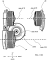
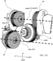
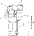
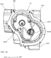
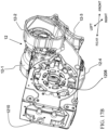
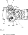
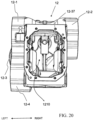
- FIG. 14-20 A preferred embodiment of a rear housing 12 of an electric work vehicle corresponding to the present invention is shown in Figs. 14-20 .
- the rear housing 12 preferably has a T-shape when viewed from above.
- the T-shape is preferably asymmetrical in a left-right direction of the electric work vehicle.
- An upper portion of the rear housing 12 preferably includes a depression portion in which the gear actuator retaining portion 1206 is defined.
- the gear actuator retaining portion 1206 is structured to support the shifting actuator 532.
- the first motor housing portion 12-1 preferably includes a motor shaft passage 12-15 which permits a shaft of the third electric motor 18 to pass into a central portion of the rear housing 12, and a gear shaft support 12-17 which supports the left motor driven pinion gear 542L.
- the second motor housing portion 12-2 preferably includes a motor shaft passage 12-25 which permits a shaft of the fourth electric motor 20 to pass into the central portion of the rear housing 12, and a gear shaft support 12-27 which supports the right motor driven pinion gear 542R.
- the third motor housing portion 12-3 preferably includes a motor shaft passage 12-35 which permits a shaft of the fifth electric motor 22 to pass into the central portion of the rear housing 12 and a PTO input shaft support 12-37 which supports the PTO input shaft gear 2300 and the PTO input shaft 504.
- the fourth motor housing portion 12-4 preferably includes a motor shaft passage 12-45 which permits a shaft of the sixth electric motor 24 to pass into the central portion of the rear housing 12 and a pump support 12-47 which supports the hydraulic pump 510.
- a portion of an upper surface of the rear frame adjacent to the fourth motor housing portion 12-4 preferably includes a parking actuator retaining portion 1204 which is structured to support the parking actuator 529.
- a rear portion of the rear housing 12 preferably defines a gear casing 1200 which houses the third gearing 19 and the fourth gearing 21.
- An upper portion of the gear casing 1200 preferably includes a gear access opening 1202 and a rear portion of the gear casing 1200 preferably includes the PTO opening 1210.
- the rear housing 12 preferably includes at least a first oil path 550 and a second oil path 560 which pass through the rear housing 12 to permit oil to be circulated back into the rear housing 12 through, for example, hydraulic/oil lines.
- the first oil path 550 is preferably provided on a right side of the rear housing 12 adjacent to the second motor housing portion 12-2.
- the first oil path 550 preferably includes a front inlet opening 551, a side inlet opening 552, a first channel 553, and a first outlet opening 554.
- the front inlet opening 551 is preferably defined in a front surface of the rear housing 12 between the second motor housing portion 12-2 and the third motor housing portion 12-3.
- the side inlet opening 552 is preferably defined is a right side surface of the rear housing 12 adjacent to the second motor housing portion 12-2.
- the first channel 553 preferably extends horizontally in the front-rear direction of the electrical vehicle.
- the front inlet opening 551 and the side inlet opening 552 preferably extend in perpendicular directions and are connected to a first channel 553 which extends in a front-rear direction of the electrical vehicle.
- the front inlet opening 551 is preferably connected to an oil return from the brake master cylinder 580 while the side inlet opening 552 is preferably connected to a main oil return line.
- the first outlet opening 554 is preferably provided at a rear end of the first channel 553 and deposits the oil into a central reservoir of the rear housing 12.
- the first outlet opening 554 is preferably located above the right motor driven pinion gear 542R, and most preferably is structured to drop oil onto the low speed gear teeth 5420R.
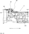
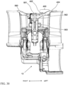
- the second oil path 560 preferably includes a top inlet opening 561, a second channel 562, and a second outlet 563, as shown in Figs. 14 and 28-31 , for example.
- the second oil path 560 preferably lubricates third and fourth shafts 1802 and 2002 of the third electric motor 18 and the fourth electric motor 20 which are connected to the left and right motor driven pinion gears 542L and 542R.
- the third and fourth shafts 1802 and 2002 are preferably at least partially hollow.
- the top inlet opening 561 is preferably provided on a central portion of an upper surface of the rear housing 12 and is connected to a low pressure oil supply.
- the second channel 562 preferably extends vertically downward from the top inlet opening 561 to a central portion of the rear housing 12.
- the second outlet 563 is provided at an axial bottom of the second channel 562 and directs the oil input into the top inlet opening 561 to components within the rear housing 12.
- the front inlet opening 551, the side inlet opening 552, and the top inlet opening 561 are preferably located forward of the third and fourth shafts 1802 and 2002 of the third electric motor 18 and the fourth electric motor 20 in the front-rear direction of the electric work vehicle.
- the oil output from the first oil path 550 is preferably introduced above the fourth shaft 2002 and oil output from the second oil path 560 is preferably introduced to a location inside of or between the third and fourth shafts 1802 and 2002, as shown in Fig. 31 .
- the rear housing 12 preferably includes a tank breather 400 which allows air to exit from an inside of the rear housing 12 to an outside of the rear housing 12.
- the tank breather 400 preferably includes a first opening 402 and a second opening 404.
- the first opening 402 preferably opens upwards out of an upper surface of the rear housing 12.
- the second opening 404 preferably opens inwards into an inner portion of the rear housing 12, to permit air to flow from the inside of the rear housing 12 into the second opening 404 and then out of the first opening 402.
- the tank breather 400 is preferably located on an opposite side of the rear housing 12 with respect to the first oil path 550 in the left-right direction of the electric work vehicle.
Landscapes
- Engineering & Computer Science (AREA)
- Mechanical Engineering (AREA)
- Transportation (AREA)
- Life Sciences & Earth Sciences (AREA)
- General Engineering & Computer Science (AREA)
- Power Engineering (AREA)
- Sustainable Energy (AREA)
- Environmental Sciences (AREA)
- Sustainable Development (AREA)
- Chemical & Material Sciences (AREA)
- Combustion & Propulsion (AREA)
- Arrangement Or Mounting Of Propulsion Units For Vehicles (AREA)
- Auxiliary Drives, Propulsion Controls, And Safety Devices (AREA)
- Arrangement Of Transmissions (AREA)
- Motor Power Transmission Devices (AREA)
- Arrangement And Driving Of Transmission Devices (AREA)
- Transmission Of Braking Force In Braking Systems (AREA)
- Connection Of Motors, Electrical Generators, Mechanical Devices, And The Like (AREA)
Applications Claiming Priority (2)
| Application Number | Priority Date | Filing Date | Title |
|---|---|---|---|
| US202363546282P | 2023-10-30 | 2023-10-30 | |
| US18/532,100 US20250133994A1 (en) | 2023-10-30 | 2023-12-07 | Electric work vehicle |
Publications (1)
| Publication Number | Publication Date |
|---|---|
| EP4549210A1 true EP4549210A1 (de) | 2025-05-07 |
Family
ID=93154357
Family Applications (1)
| Application Number | Title | Priority Date | Filing Date |
|---|---|---|---|
| EP24207251.0A Pending EP4549210A1 (de) | 2023-10-30 | 2024-10-17 | Elektrisches arbeitsfahrzeug |
Country Status (3)
| Country | Link |
|---|---|
| US (1) | US20250133994A1 (de) |
| EP (1) | EP4549210A1 (de) |
| JP (1) | JP2025078598A (de) |
Citations (3)
| Publication number | Priority date | Publication date | Assignee | Title |
|---|---|---|---|---|
| US20080264026A1 (en) * | 2007-04-24 | 2008-10-30 | Kanzaki Kokyukoki Manufacturing Co., Ltd. | Riding lawnmower vehicle |
| US9242544B2 (en) * | 2011-09-23 | 2016-01-26 | Kanzaki Kokyukoki Mfg. Co., Ltd. | Vehicle with electric transaxle |
| JP6433367B2 (ja) * | 2015-04-08 | 2018-12-05 | 株式会社クボタ | 電動作業車両 |
Family Cites Families (8)
| Publication number | Priority date | Publication date | Assignee | Title |
|---|---|---|---|---|
| US5924504A (en) * | 1997-02-18 | 1999-07-20 | Meritor Heavy Vehicle Systems, Llc | Suspension drive unit assembly for an electrically driven vehicle |
| DE10248173A1 (de) * | 2002-10-16 | 2004-05-13 | Zf Friedrichshafen Ag | Fahrzeug mit elektrischen Einzelradantrieben |
| US8701806B2 (en) * | 2009-03-18 | 2014-04-22 | Kanzaki Kokyukoki Mfg. Co., Ltd. | Electric transaxle unit |
| DE102009033531A1 (de) * | 2009-07-10 | 2011-01-20 | Dr. Ing. H.C. F. Porsche Aktiengesellschaft | Antriebsvorrichtung für ein Kraftfahrzeug mit einer elektrische Maschinen aufweisenden Portalachse |
| JP6436841B2 (ja) * | 2015-04-09 | 2018-12-12 | 株式会社クボタ | 電動作業車両 |
| US10742094B1 (en) * | 2017-02-03 | 2020-08-11 | Wrightspeed, Inc. | Temperature monitoring of magnets in permanent magnet motors used in vehicle drivetrains |
| US11639092B1 (en) * | 2022-03-25 | 2023-05-02 | Dimaag-Ai, Inc. | Controlling stability of electric vehicles |
| US11878693B1 (en) * | 2023-06-09 | 2024-01-23 | Dimaag-Ai, Inc. | Electrical vehicles comprising power distribution systems and methods of operating thereof |
-
2023
- 2023-12-07 US US18/532,100 patent/US20250133994A1/en active Pending
-
2024
- 2024-10-17 EP EP24207251.0A patent/EP4549210A1/de active Pending
- 2024-10-23 JP JP2024186349A patent/JP2025078598A/ja active Pending
Patent Citations (3)
| Publication number | Priority date | Publication date | Assignee | Title |
|---|---|---|---|---|
| US20080264026A1 (en) * | 2007-04-24 | 2008-10-30 | Kanzaki Kokyukoki Manufacturing Co., Ltd. | Riding lawnmower vehicle |
| US9242544B2 (en) * | 2011-09-23 | 2016-01-26 | Kanzaki Kokyukoki Mfg. Co., Ltd. | Vehicle with electric transaxle |
| JP6433367B2 (ja) * | 2015-04-08 | 2018-12-05 | 株式会社クボタ | 電動作業車両 |
Also Published As
| Publication number | Publication date |
|---|---|
| US20250133994A1 (en) | 2025-05-01 |
| JP2025078598A (ja) | 2025-05-20 |
Similar Documents
| Publication | Publication Date | Title |
|---|---|---|
| EP4549193A1 (de) | Elektrisches arbeitsfahrzeug | |
| EP4549210A1 (de) | Elektrisches arbeitsfahrzeug | |
| EP4574496A1 (de) | Elektrisches arbeitsfahrzeug | |
| EP4549214A1 (de) | Elektrisches arbeitsfahrzeug | |
| EP4549213A1 (de) | Elektrisches arbeitsfahrzeug | |
| EP4549666A1 (de) | Elektrisches arbeitsfahrzeug | |
| EP4552879A1 (de) | Elektrisches arbeitsfahrzeug | |
| EP4556274A1 (de) | Elektrisches arbeitsfahrzeug | |
| EP4552880A1 (de) | Elektrisches arbeitsfahrzeug | |
| EP4570548A1 (de) | Elektrisches arbeitsfahrzeug | |
| EP4549195A2 (de) | Elektrisches arbeitsfahrzeug | |
| EP4549194A1 (de) | Elektrisches arbeitsfahrzeug | |
| EP4556276A1 (de) | Elektrisches arbeitsfahrzeug | |
| EP4549196A2 (de) | Elektrisches arbeitsfahrzeug | |
| US12617258B2 (en) | Electric work vehicle | |
| US12358574B2 (en) | Electric work vehicle | |
| US20250133993A1 (en) | Electric work vehicle | |
| EP4549212A1 (de) | Elektrisches arbeitsfahrzeug |
Legal Events
| Date | Code | Title | Description |
|---|---|---|---|
| PUAI | Public reference made under article 153(3) epc to a published international application that has entered the european phase |
Free format text: ORIGINAL CODE: 0009012 |
|
| STAA | Information on the status of an ep patent application or granted ep patent |
Free format text: STATUS: THE APPLICATION HAS BEEN PUBLISHED |
|
| AK | Designated contracting states |
Kind code of ref document: A1 Designated state(s): AL AT BE BG CH CY CZ DE DK EE ES FI FR GB GR HR HU IE IS IT LI LT LU LV MC ME MK MT NL NO PL PT RO RS SE SI SK SM TR |
|
| STAA | Information on the status of an ep patent application or granted ep patent |
Free format text: STATUS: REQUEST FOR EXAMINATION WAS MADE |
|
| 17P | Request for examination filed |
Effective date: 20251104 |
|
| GRAP | Despatch of communication of intention to grant a patent |
Free format text: ORIGINAL CODE: EPIDOSNIGR1 |
|
| STAA | Information on the status of an ep patent application or granted ep patent |
Free format text: STATUS: GRANT OF PATENT IS INTENDED |
|
| RIC1 | Information provided on ipc code assigned before grant |
Ipc: B60K 7/00 20060101AFI20260302BHEP Ipc: B60K 1/02 20060101ALI20260302BHEP Ipc: B60K 17/04 20060101ALI20260302BHEP Ipc: B60K 17/356 20060101ALI20260302BHEP Ipc: F16H 1/20 20060101ALI20260302BHEP Ipc: F16H 57/04 20100101ALI20260302BHEP Ipc: B60L 1/00 20060101ALI20260302BHEP Ipc: B60L 50/51 20190101ALI20260302BHEP Ipc: B60L 50/64 20190101ALI20260302BHEP Ipc: B60L 50/60 20190101ALI20260302BHEP Ipc: B60L 58/21 20190101ALI20260302BHEP Ipc: B60K 1/04 20190101ALN20260302BHEP Ipc: F16H 57/02 20120101ALN20260302BHEP |
|
| INTG | Intention to grant announced |
Effective date: 20260316 |
|
| RIC1 | Information provided on ipc code assigned before grant |
Ipc: B60K 7/00 20060101AFI20260306BHEP Ipc: B60K 1/02 20060101ALI20260306BHEP Ipc: B60K 17/04 20060101ALI20260306BHEP Ipc: B60K 17/356 20060101ALI20260306BHEP Ipc: F16H 1/20 20060101ALI20260306BHEP Ipc: F16H 57/04 20100101ALI20260306BHEP Ipc: B60L 1/00 20060101ALI20260306BHEP Ipc: B60L 50/51 20190101ALI20260306BHEP Ipc: B60L 50/64 20190101ALI20260306BHEP Ipc: B60L 50/60 20190101ALI20260306BHEP Ipc: B60L 58/21 20190101ALI20260306BHEP Ipc: B60K 1/04 20190101ALN20260306BHEP Ipc: F16H 57/02 20120101ALN20260306BHEP |
|
| GRAS | Grant fee paid |
Free format text: ORIGINAL CODE: EPIDOSNIGR3 |
|
| GRAA | (expected) grant |
Free format text: ORIGINAL CODE: 0009210 |
|
| STAA | Information on the status of an ep patent application or granted ep patent |
Free format text: STATUS: THE PATENT HAS BEEN GRANTED |