EP4549366A1 - Procédé pour exécuter une fonction - Google Patents
Procédé pour exécuter une fonction Download PDFInfo
- Publication number
- EP4549366A1 EP4549366A1 EP23206953.4A EP23206953A EP4549366A1 EP 4549366 A1 EP4549366 A1 EP 4549366A1 EP 23206953 A EP23206953 A EP 23206953A EP 4549366 A1 EP4549366 A1 EP 4549366A1
- Authority
- EP
- European Patent Office
- Prior art keywords
- lifting device
- arm system
- load
- movement
- predetermined
- Prior art date
- Legal status (The legal status is an assumption and is not a legal conclusion. Google has not performed a legal analysis and makes no representation as to the accuracy of the status listed.)
- Pending
Links
Images




Classifications
-
- B—PERFORMING OPERATIONS; TRANSPORTING
- B66—HOISTING; LIFTING; HAULING
- B66C—CRANES; LOAD-ENGAGING ELEMENTS OR DEVICES FOR CRANES, CAPSTANS, WINCHES, OR TACKLES
- B66C23/00—Cranes comprising essentially a beam, boom, or triangular structure acting as a cantilever and mounted for translatory of swinging movements in vertical or horizontal planes or a combination of such movements, e.g. jib-cranes, derricks, tower cranes
- B66C23/54—Cranes comprising essentially a beam, boom, or triangular structure acting as a cantilever and mounted for translatory of swinging movements in vertical or horizontal planes or a combination of such movements, e.g. jib-cranes, derricks, tower cranes with pneumatic or hydraulic motors, e.g. for actuating jib-cranes on tractors
-
- B—PERFORMING OPERATIONS; TRANSPORTING
- B66—HOISTING; LIFTING; HAULING
- B66C—CRANES; LOAD-ENGAGING ELEMENTS OR DEVICES FOR CRANES, CAPSTANS, WINCHES, OR TACKLES
- B66C13/00—Other constructional features or details
- B66C13/16—Applications of indicating, registering, or weighing devices
-
- B—PERFORMING OPERATIONS; TRANSPORTING
- B66—HOISTING; LIFTING; HAULING
- B66C—CRANES; LOAD-ENGAGING ELEMENTS OR DEVICES FOR CRANES, CAPSTANS, WINCHES, OR TACKLES
- B66C23/00—Cranes comprising essentially a beam, boom, or triangular structure acting as a cantilever and mounted for translatory of swinging movements in vertical or horizontal planes or a combination of such movements, e.g. jib-cranes, derricks, tower cranes
- B66C23/62—Constructional features or details
- B66C23/64—Jibs
- B66C23/70—Jibs constructed of sections adapted to be assembled to form jibs or various lengths
- B66C23/701—Jibs constructed of sections adapted to be assembled to form jibs or various lengths telescopic
-
- B—PERFORMING OPERATIONS; TRANSPORTING
- B66—HOISTING; LIFTING; HAULING
- B66C—CRANES; LOAD-ENGAGING ELEMENTS OR DEVICES FOR CRANES, CAPSTANS, WINCHES, OR TACKLES
- B66C23/00—Cranes comprising essentially a beam, boom, or triangular structure acting as a cantilever and mounted for translatory of swinging movements in vertical or horizontal planes or a combination of such movements, e.g. jib-cranes, derricks, tower cranes
- B66C23/88—Safety gear
- B66C23/90—Devices for indicating or limiting lifting moment
- B66C23/905—Devices for indicating or limiting lifting moment electrical
Definitions
- the invention relates to a method for carrying out a predetermined or predeterminable function of a lifting device according to the preamble of claim 1, a control for a lifting device for carrying out such a method and a lifting device with such a control.
- Methods for performing a predetermined or predeterminable function of a lifting device are known in the prior art, in which the lifting device must be brought into a predetermined position of an arm system of the lifting device. Methods are also known in which a predetermined or predeterminable function is performed in a state of the lifting device in which the lifting device is at a standstill.
- the methods known in the prior art pose additional requirements for a user, since the lifting device must be brought into a predetermined position of the arm system in order to perform a predetermined or predeterminable function, or the movement and thus the work with the lifting device must be interrupted because the lifting device must be at a standstill in order to perform a predetermined or predeterminable function. This is disadvantageously associated with increased demands on the operation of a lifting device and increased time expenditure for carrying out a lifting operation.
- the object of the invention is to provide an improved method for carrying out a predetermined or predeterminable function of a lifting device, a control for a lifting device for carrying out such a method and a lifting device with such a control.
- This object is achieved by a method for carrying out a predetermined or predeterminable function of a lifting device having the features of claim 1, a control for a lifting device for carrying out such a method and a lifting device having such a control.
- a method according to the invention can execute a predetermined or predeterminable function of a lifting device depending on at least one trigger interface.
- the method can preferably execute a predetermined or predeterminable function of a hydraulic lifting device.
- a lifting device may comprise an arm system with arms having a variable geometry, wherein, during a movement of the lifting device, the arms of the arm system can be moved relative to one another by at least one actuator along at least one degree of freedom.
- the arm system may, for example, be a crane column, a lifting arm, an articulated arm with at least one crane extension arm, at least one knuckle arm extension with at least one crane extension arm and/or a boom extension.
- a movement along a degree of freedom can be achieved by an actuator corresponding to the degree of freedom.
- an actuator corresponding to the degree of freedom.
- two pivotally mounted arms can be pivoted relative to each other by an actuator.
- Two displaceably mounted arms can be displaced relative to each other by an actuator, for example.
- Actuators for moving the lifting device and/or an arm system of the lifting device can be electrical and/or hydraulic.
- the degrees of freedom of the arm system can generally include angles between the arms of the arm system and the lengths of adjustable arms.
- the arm system can exhibit a degree of freedom of rotation through a rotatable mounting in a base.
- Values of degrees of freedom of movement can be detected by suitable sensors, such as angle sensors, position sensors for lengths of length-adjustable arms and/or length-adjustable actuators, and can be fed to a control of the lifting device in the form of at least one sensor signal.
- suitable sensors such as angle sensors, position sensors for lengths of length-adjustable arms and/or length-adjustable actuators
- the lifting device can be controlled by controlling actuators through control commands issued by the controller. Actuators of the lifting device can be specifically controlled based on operating commands from a user through corresponding control commands issued by the controller.
- the controller can have a suitable user interface or human-machine interface for issuing operating commands by a user.
- the controller can be remotely controlled using a remote control, which can have at least one user interface for issuing operating commands by a user. Based on the operating commands, the controller can generate control commands for controlling the lifting device.
- the controller can generally have at least one processing unit and at least one memory unit.
- the processing unit can be connected to the memory unit or can be connected to it.
- a user interface of a control and/or a remote control can be menu-driven and/or with an input mask in the form of user guidance with a graphical, character-oriented, or voice-oriented user interface.
- a specification of at least one parameter for a relative position of the at least one trigger interface relative to the lifting device can be done via the user interface, in particular input devices.
- the lifting device can have at least one working device that can be arranged on an arm system.
- a working device can basically be understood as an attachment that can be arranged on the arm system for manipulating objects or items, for example a load to be lifted.
- the arm system and the working device preferably the at least one movable part of the working device, can be controlled separately or jointly by appropriate control commands.
- the working device can be designed as a gripper with two or more gripper jaws or gripper shells that can be moved relative to one another.
- One working device can be designed in the form of a rotator for moving another working device relative to the arm system. The movements of the at least one working device can be driven by appropriate actuators.
- a movement of the lifting device can be effected by a substantially free control of actuators by issuing operating commands by a user, preferably via a suitable user interface or human-machine interface of a control system.
- individual actuators of the lifting device can be specifically controlled based on operating commands from a user by corresponding control commands, for example issued by a control system.
- a movement of the lifting device can also be effected in the form of a coordinate control (also called " boom tip control " ) of the The individual actuators of the arm system are controlled by the controller in such a way that the user controls the behavior of a crane tip of the arm system, instead of controlling the individual actuators themselves as usual.
- At least one parameter for a relative position of the at least one trigger interface relative to the lifting device can be specified.
- a specification can be made by at least one sensor signal from a sensor of the lifting device that is in data communication with a controller of the lifting device.
- a specification can be made by a user via at least one user interface of a controller of the lifting device.
- the at least one trigger interface can be created.
- At least one predetermined or predeterminable function of the lifting device can be executed.
- at least one predetermined or predeterminable function of the lifting device when a predetermined or predeterminable point of an arm system of the lifting device approaches the at least one trigger interface, at least one predetermined or predeterminable function of the lifting device can be executed.
- a predetermined or predeterminable point of an arm system of the lifting device passes through the at least one trigger interface, at least one predetermined or predeterminable function of the lifting device.
- the at least one trigger interface can be created by a control system of the lifting device.
- the approach and/or passage can be detected by the control system of the lifting device.
- at least one parameter for a relative position of the at least one trigger interface relative to the lifting device can be stored in a memory unit.
- the approach and/or passage can be detected using values of degrees of freedom of the movement of the arm system of the lifting device supplied to the control system.
- the at least one predetermined or predeterminable function of the lifting device can be executed by a controller of the lifting device. For example, upon detecting an approach of a person and/or a stepping through, a computing unit of the controller can execute commands that cause the controller to execute the at least one predetermined or predeterminable function.
- a predetermined or predeterminable point of an arm system of the lifting device can correspond to a tip of the arm system, a position of a working device arranged on the lifting device, in particular on the arm system, or an essentially freely selectable point of the arm system.
- Execution of at least one predetermined or predeterminable function of the lifting device upon approach of a predetermined or predeterminable point of an arm system of the lifting device to the at least one trigger interface and/or upon passage of a predetermined or predeterminable point of an arm system of the lifting device through the at least one trigger interface can be repeated essentially as often as desired.
- the execution can be repeated upon repeated loading of loads, preferably upon repeated loading of loads onto or from a loading space.
- a trigger interface can, in principle, be an essentially two-dimensional subset of three-dimensional space, a two-dimensional geometric figure, or a boundary surface of a three-dimensional body.
- a trigger interface can be at least partially flat and/or at least partially curved.
- a trigger interface can be limited in at least one spatial direction.
- a trigger interface can be limited in a vertical extension, a longitudinal extension, and/or a radius.
- a user of a lifting device By executing a function depending on a trigger interface, a user of a lifting device does not have to place it in a predetermined position of an arm system or interrupt the movement and thus the work with the lifting device.
- a position of an arm system of the lifting device and/or movement of the lifting device that is at least partially identical or approximate within a range can be approached and/or passed through with each repetition.
- a range can be related to an interval or intervals of values of the degrees of freedom of the movement of the arm system.
- a user of the lifting device does not have to move to a predetermined position of an arm system or interrupt the movement and thus the work with the lifting device when executing the function, as well as for a repeated execution of the function, but only has to approach a predetermined or predeterminable point of an arm system of the lifting device to the at least one trigger interface and/or pass through the at least one trigger interface with a predetermined or predeterminable point of an arm system of the lifting device.
- an interface between at least a part of an interior region of a loading area of the lifting device and at least a part of an exterior region of the loading area of the lifting device can be created
- at least one parameter for a relative position of the at least one trigger interface relative to the lifting device can be predetermined as a function of a position of a loading area of the lifting device provided for depositing loads lifted by the lifting device.
- a loading area of the lifting device can, for example, correspond to a loading area of a carrier vehicle of the lifting device and/or a loading area of at least one trailer.
- the at least one trailer can be positionable relative to the lifting device.
- a loading area can have a longitudinal extension along a longitudinal axis.
- a loading area can have a transverse extension along a transverse axis.
- a parameter for a relative position of the at least one trigger interface relative to the lifting device can be specified, for example, in the form of an angular position of a longitudinal axis of a loading area and/or a transverse axis of a loading area relative to a predetermined or predeterminable spatial direction.
- a predetermined or The predefined spatial direction can be related to the lifting device.
- a predefined spatial direction can correspond to a longitudinal axis of a carrier vehicle of the lifting device or be related to it.
- At least one parameter for a relative position of the at least one trigger interface relative to the lifting device can be specified as a function of the position of a loading area by at least one sensor signal from a sensor of the lifting device that is in data communication with a controller of the lifting device.
- An angular position of a longitudinal axis of a loading area and/or a transverse axis of a loading area relative to a predetermined or predeterminable spatial direction can be detected.
- an angular position of a longitudinal axis of a loading area relative to a longitudinal axis of a carrier vehicle of the lifting device can be detected and specified as a parameter.
- a parameter can be specified as a function of the position of a loading area by a user via at least one user interface of a controller of the lifting device.
- An angular position of a longitudinal axis of a loading area relative to a longitudinal axis of a carrier vehicle of the lifting device can be specified by a user via at least one user interface of a controller of the lifting device, for example, by entering an angular position into an input mask of the user interface.
- a function for determining at least one load value of a load lifted by the hydraulic lifting device can be carried out during the approach and/or the passage.
- a load value may be a unit value for the mass of a load lifted by the hydraulic lifting device.
- a load value determined using the method can be displayed to a user.
- the display can be in the form of a user-perceptible, particularly visual and/or acoustic, indication of the at least one load value for the lifted load.
- determining at least one load value for example, the sum of a load lifted during operation of a lifting device can be determined.
- Determining at least one load value can generally be performed continuously, for example, at a certain clock frequency.
- a clock frequency can specify how often a determination is made within a certain time interval.
- Assigning a load value to a lifted load can be done by executing the function upon approach and/or passing through.
- a function in the form of determining at least one load value of a load lifted by the hydraulic lifting device as a function of approaching and/or passing through a trigger interface advantageous states of a position and/or movement of the lifting device for determining at least one load value can be created.
- a function when approaching and/or passing through a predetermined or predeterminable point of an arm system of the lifting device to and/or through the at least one trigger interface, a The position of an arm system of the lifting device and/or movement of the lifting device can be approached and/or passed through.
- a user of the lifting device does not have to move to a predetermined position of an arm system or interrupt the movement and thus the work with the lifting device, but only has to approach a predetermined or predeterminable point of an arm system of the lifting device to the at least one trigger interface and/or pass through the at least one trigger interface with a predetermined or predeterminable point of an arm system of the lifting device.
- a predetermined or predeterminable point of an arm system of the lifting device can be repeatedly approached and/or passed through the at least one triggering interface.
- a position of an arm system of the lifting device and/or movement of the lifting device that is at least partially identical or approximate within a range can be approached and/or passed through.
- the at least one load value determined during each repetition can thus be determined for positions of an arm system of the lifting device and/or movements of an arm system of the lifting device that are at least partially identical or approximate within a range.
- a movement of an arm system of the hydraulic lifting device can take place along at least one degree of freedom of movement of the arm system with a lifted load.
- an essentially freely selectable movement can occur along at least one degree of freedom of the movement of the arm system.
- At least one determination of the dynamic load moments of the arms of the arm system prevailing during the movement can be carried out, whereby at least one load value for the lifted load can be determined by taking into account the dynamic load moments.
- Dynamic load moments can be caused by loads on the arms of the arm system occurring during a movement of the arm system due to their inherent masses and their outsourcing, as well as by the mass or masses of a lifted load and their outsourcing.
- a bearing arrangement can be provided, for example, by a horizontal or radial distance from a vertical axis of an arm system, preferably a vertical pivot axis of a bearing arrangement of an arm system.
- bearing friction of bearing points of arms of an arm system can have a lesser influence on the determination of dynamic load moments than with a static measurement at standstill.
- At least one determination of the dynamic load moments prevailing during the movement due to the dead masses of the arms of the arm system is carried out, whereby at least one load value can be determined by taking the dynamic load moments into account.
- a load value can be determined as a reference value for an unloaded lifting device.
- the at least one load value can be recorded in a load value sequence.
- a repeated determination of at least one load value of a load lifted by the hydraulic lifting device can be carried out, where the repeatedly determined load value can be recorded in a load value sequence.
- the load value sequence can correspond to a chronologically ordered set of recorded load values.
- a recording of at least one load value in a load value sequence can be performed continuously, for example, at a certain clock frequency.
- a clock frequency can specify how often a recording occurs within a certain time interval.
- a recording of at least one load value in a load value sequence can be performed during a movement of the lifting device with a lifted load.
- a recording of at least one load value in a load value sequence can be performed during a movement of the lifting device with the lifting device unloaded.
- a determination of the at least one load value and a recording of the at least one load value in a load value sequence can in principle take place during the entire operation of a lifting device.
- a determination of the at least one load value and a recording of the at least one load value in a load value sequence can be carried out continuously during substantially the entire duration of a movement of an arm system.
- At least one recorded load value can be selected from the load value sequence.
- At least one load value that was determined during the approach and/or passage can be selected from the load value sequence.
- a selection may be made of at least one recorded load value from the load value sequence which was determined within a time interval before, after or around the approach and/or the passage.
- the load value attributable to a load lifted by the hydraulic lifting device can be determined from the at least one selected load value.
- load values can be included in the determination which were determined for positions of an arm system of the lifting device and/or movements of an arm system of the lifting device which are at least partially identical or approximate within a range.
- load values can be selected, for example, which were determined during approach and/or passing through.
- the load value can be determined from an arithmetic mean of the at least one selected load value.
- the load value can be determined from a weighted arithmetic mean, wherein weighting can be performed according to at least one specific selection criterion.
- a movement of an arm system of the hydraulic lifting device can take place along at least one degree of freedom of the movement of the arm system, wherein in at least one time interval during the movement of the arm system at least one detection of the values prevailing in the at least one time interval of at least one of the degrees of freedom of the movement of the arm system and at least one detection of at least one force acting on the arm system in the at least one time interval can take place.
- Suitable sensors can be provided to detect at least one force.
- a recording of prevailing values of at least one of the degrees of freedom of the movement of the arm system and a recording of at least one force acting on the arm system can be carried out in order to determine the dynamic loading moments of the arms of the arm system prevailing during the movement.
- a selection of at least one recorded load value from the load value sequence and/or a weighting may include at least one of the following selection criteria: A selection can be made depending on a minimum duration and/or a maximum duration for at least one time interval.
- a selection can be made depending on a specification of a time interval through an interaction by a user, for example via at least one user interface of a control of the lifting device.
- a selection can be made depending on a minimum value and/or a maximum value and/or an interval for the recorded values of at least one of the degrees of freedom of movement of the arm system. This allows load values to be selected that are at least partially identical or approximate within a range for positions of an arm system of the lifting device and/or movements of an arm system of the lifting device.
- a selection can be made based on a minimum value and/or a maximum value and/or an interval for the at least one detected force. This allows load values to be selected that were determined when the lifting device was loaded. Load values that lie within technically plausible limits can also be selected, for example, to rule out false signals from sensors.
- a selection can be made depending on a minimum value and/or a maximum value and/or an interval for a rate of change of the detected values of at least one of the degrees of freedom of the arm system's movement. This allows load values to be selected that were determined during a movement along at least one degree of freedom of the arm system that is at least partially substantially uniform.
- a selection can be made depending on a minimum value and/or a maximum value and/or an interval for a rate of change of the at least one detected force. This allows load values to be selected that were determined during a substantially uniform movement along at least one degree of freedom of the arm system, at least in sections.
- the at least one parameter can be specified via at least one user interface of the control system of the lifting device by issuing operating commands for a movement of an arm system having a plurality of degrees of freedom of movement with a plurality of arms along at least one of the degrees of freedom.
- at least one point of the at least one trigger interface can be specified by a user by positioning a predetermined or predefinable point of the arm system of the lifting device by issuing operating commands for a movement of the arm system.
- at least a height, a longitudinal extent, an inclination, a center point or a spatial coordinate of a point of the at least one trigger interface can be specified.
- Several parameters of the at least one trigger interface can be specified.
- the at least one parameter can be specified via at least one user interface of the control system of the lifting device by a user entering at least one distance value and/or an angle value for a relative position of the at least one trigger interface relative to the lifting device.
- At least one height, a longitudinal extent, an inclination, a center point, or a spatial coordinate of a point of the at least one trigger interface can also be specified. Multiple parameters of the at least one trigger interface can be specified.
- the specification of the at least one parameter is carried out by issuing operating commands, a determination of at least one value of the at least one parameter that can be processed by the controller and at least one sensor signal that can be detected by a controller of the lifting device from at least one sensor arranged or that can be arranged on the lifting device can be carried out.
- Sensors arranged or arrangeable on the lifting device may generally include angle sensors, length sensors, position sensors, and/or optical sensors such as infrared sensors, ultrasonic sensors, and/or a camera.
- Execution of the at least one predetermined or predeterminable function of the lifting device upon approaching the at least one triggering interface can occur within a predetermined or predeterminable distance from a predetermined or predeterminable point of the arm system of the lifting device.
- a specification can be made via at least one user interface of the control system of the lifting device, for example, by entering at least one distance value.
- Protection is also sought for a control system for a lifting device which comprises means for carrying out the method described above.
- the control can be configured to specify at least one parameter for a relative position of the at least one trigger interface relative to the lifting device by at least one sensor signal of a sensor of the lifting device that is in data communication with a control of the lifting device and/or via at least one user interface of a control of the lifting device by a user.
- the controller may be configured to create the at least one trigger interface depending on the at least one parameter.
- the controller can be configured to execute at least one predetermined or predeterminable function of the lifting device when a predetermined or predeterminable point of an arm system of the lifting device approaches the at least one trigger interface and/or when a predetermined or predeterminable point of an arm system of the lifting device passes through the at least one trigger interface.
- a computer program product may comprise instructions which cause the previously described controller configured to carry out the method, optionally in an arrangement with a lifting device preferably equipped with corresponding sensors, to carry out a method as described above.
- Instructions of a computer program product can, for example, be stored in at least one memory unit of the controller and executed by at least one computing unit of the controller.
- the lifting device can be designed as a loading crane or a timber crane.
- the lifting device can be designed as a hydraulic crane.
- the lifting device can be arranged on a carrier vehicle to form a vehicle with a lifting device.
- the carrier vehicle can have a loading area for cargo.
- the carrier vehicle can be arranged with at least one trailer having a loading area, which can be positioned relative to the lifting device.
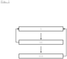
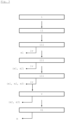
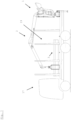
- FIGS. 1 to 3 show schematically embodiments of a process for executing a predetermined or predeterminable function.
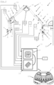
- Figure 4 shows an embodiment of a lifting device 1 with a controller 11 having a user interface 21 and a lifted load 3, wherein the degrees of freedom w, k1, k2, s1, s2, a of the movement of the arm system 2 having a plurality of arms 4, 5, 6, 7, 8, 9 and a trigger interface 20 positioned relative to the lifting device are illustrated.
- Figure 5 shows a further schematic representation of a lifting device 1.
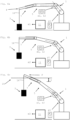
- the Figures 6a to 6c show a schematic representation of a movement of a lifting device 1.
- Figure 7 shows an embodiment of a vehicle 17 with a rear-mounted lifting device 1 with a loading area 19.
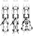
- the Figures 8a and 8b show schematic views of different arrangements of a vehicle 17 with a Lifting device 1 and a trailer 23 with a specification of at least one parameter for a trigger interface 20.
- the Figures 9a and 9b show schematic views of different arrangements of a vehicle 17 with a lifting device 1 and a trailer 23 with a specification of at least one parameter for a trigger interface 20.
- the Figures 10a to 10c schematic views of user interface options 21.
- Figure 1 shows schematically a sequence of an embodiment of a method for carrying out a predetermined or predeterminable function of a lifting device 1 in dependence on at least one trigger interface 20.
- a specification i of at least one parameter for a relative position of the at least one trigger interface 20 relative to the lifting device 1 can be made by at least one sensor signal of a sensor of the lifting device 1 that is in data communication with a controller 11 of the lifting device 1 and/or a specification via at least one user interface 21 of a controller 11 of the lifting device 1 by a user.
- At least one trigger interface 20 can be created.
- the specification of at least one parameter and the corresponding creation of at least one, optionally additional, trigger interface 20 can be repeated. Multiple trigger interfaces 20 can also be created using parameters.
- FIG. 2 an embodiment of the method is shown in which, during the approach and/or the passing through, a function for determining at least one load value m1, m2, m3 of a load 3 lifted by the hydraulic lifting device 1 is carried out.
- a movement of an arm system 2 of the hydraulic lifting device 1 can take place along at least one degree of freedom w, k1, k2, s1, s2, a of the movement of the arm system 2 with a lifted load e, wherein during the movement of the arm system 2 at least one determination of the dynamic load moments of the arms 4, 5, 6, 7, 8, 9 of the arm system 2 prevailing during the movement takes place, wherein taking into account the dynamic load moments at least one load value m1, m2, m3 for the lifted load 3 can be determined.
- At least one load value m1, m2, m3 can be continuously determined for the lifted load 3.
- a load value m1, m2, m3 can be assigned to a lifted load 3 by executing the function iii.
- a recording iv of the at least one load value m1, m2, m3 in a load value sequence (m1, m2, m3) can be carried out.
- a selection v of at least one recorded load value m1, m2, m3 from the load value sequence (m2, m3) can be carried out and an adjusted load value m can be determined vi from the at least one selected load value m1, m2, m3.
- FIG 4 an embodiment of a lifting device 1 with a controller 11 and sensors arranged on the arm system 2 of the lifting device 1 is shown.
- the arm system 2 of the lifting device 1 comprises a crane column 5 pivotably mounted in a base 4, a lifting arm 6 pivotably mounted thereon, and an articulated arm 7 pivotably mounted thereon.
- the lifting arm 6 is arranged at a first articulation angle k1 on the crane column 5, and the articulated arm 7 is arranged at a second articulation angle k2 on the lifting arm 6.
- Actuators 14, 15 are provided for pivoting the lifting arm 6 and the articulated arm 7. provided.
- the articulated boom 7 has two extension arms 8, 9, by means of which the length of the articulated boom 7 can be changed.
- a freely suspended working device 10 in the form of a grab is arranged at the crane tip, which in the embodiment shown is formed by the free end of the articulated boom 7.
- the tip 18 of the articulated arm 7 is specified as a point P of the arm system 2 related to the approach to and/or passage through the trigger interface 20.
- a point on the working device 10 or a point along the arm system 2 can also be specified.
- the sensor system of the lifting device 1 comprises a sensor d4 for detecting a pivoting position w of the crane column 5 relative to the base 4, a sensor d1 for detecting the first articulation angle k1, a sensor d2 for detecting the second articulation angle k2, a thrust position sensor 11 for detecting the thrust position s1 of the first thrust arm 8 and a second thrust position sensor 12 for detecting the thrust position s2 of the second thrust arm 9.
- the working device 3 arranged on the lifting device 1 and designed as a gripper has a sensor d3 for detecting the opening angle a.
- Suitable sensors p1, p2, such as pressure sensors or power sensors, can be provided to detect at least one operating parameter of the actuators 14, 15, with which forces acting on the actuators can be detected.
- the sensors installed on the lifting device 1 can detect the geometry of the arm system 2.
- the controller 11 can have signal inputs for supplying sensor signals via signal lines of the sensors and signal outputs for outputting control commands at least to the actuators 14, 15.
- the controller 11 has a computing unit 11 and a memory unit 13.
- the controller has a user interface 21, which is suitable for specifying at least one parameter for a relative position of the at least one trigger interface 20 relative to the lifting device 1.
- the user interface 21 can be connected to the controller 11 and/or a remote control 22 of the controller 11 and can be menu-driven and/or have an input mask in the form of user guidance with a graphical, character-oriented, or voice-oriented user interface.
- a specification of at least one parameter for a relative position of the at least one trigger interface 20 relative to the lifting device 1 can be made via the user interface 21, in particular input means.
- a specification i of at least one parameter via at least one user interface 21 of the control 11 of the lifting device 1 can in this embodiment be carried out by entering at least one distance value D and/or a Angle value N for a relative position of the at least one trigger interface 20 relative to the lifting device 1.
- a specification i of at least one parameter of the at least one trigger interface 20 can also be carried out as in the Figures 8a, 8b , 9a, 9b shown.
- Execution iii of the at least one predetermined or predeterminable function of the lifting device 1 upon approach to the at least one trigger interface 20 can take place within a predetermined or predeterminable distance x of a predetermined or predeterminable point P of the arm system 2 of the lifting device 1.
- a predetermined or predeterminable distance x is shown by way of example in the Figures 4 , 6c , 9a and 9b shown.
- FIG 5 A further schematic representation of a lifting device 1 is shown.
- the design essentially corresponds to that of the Figure 4 , wherein the articulated arm 7 is formed from two push arms 7, 8 for simplified representation.
- Load moments acting on the arm system 2 can be caused by loads on the arms 4, 5, 6, 7, 8, 9 of the arm system 2 due to their inherent masses and their outsourcing, as well as by the mass or masses of a lifted load 3 and their outsourcing.
- the loads can be added by the inherent masses and the outsourcing of the arms 4, 5, 6, 7, 8, 9 of the arm system 2 by the masses of the centers of gravity SP6, SP8, SP9 of the arms 4, 5, 6, 7, 8, 9, 6, 8, 9 and their offsets r6, r8, r9 contribute to the load.
- the dead masses of the centers of gravity SP15, SP10 of an actuator 15 and a work tool 10 and their offsets r15, r10 can be added to the load.
- the mass of the center of gravity SP3 of load 3 and its offset r3 can contribute to the load.
- an offset r3, r6, r8, r9, r10, r15 can be given by a horizontal or radial distance from a vertical pivot axis of a bearing of an arm system 2 and can be determined, for example, trigonometrically from known dimensions of arms 4, 5, 6, 7, 8, 9 of the arm system 2 and sensors installed on the lifting device 2.
- the pivot axis of a bearing can run through the crane column 5.
- FIG. 6a, 6b, 6c is a schematic representation of a lifting movement of a lifting device 1 with a load 3 attached to it by a load rope 16.
- the design of the lifting device 1 can essentially be that of the Figures 4 or 5 are equivalent to.
- an exemplary movement i of the arm system 2 takes place along a degree of freedom w, k1, k2, s1, s2, a of the bending angle k2.
- a function for determining at least one load value m1, m2, m3 of a load 3 lifted by the hydraulic lifting device 1 can be executed.
- at least one load value m1, m2, m3 can be continuously determined for the lifted load 3, and upon approaching and/or passing through, a load value m1, m2, m3 can be assigned to a lifted load 3 by executing the function.
- a recording iv of the recorded load values m1, m2, m3 can be carried out in a load value sequence and, depending on at least one predetermined or predeterminable selection criterion, a selection v of at least one recorded load value m2, m3 from the load value sequence can be carried out.
- Figure 6c a selection v of at least one recorded load value m3 from the load value sequence.
- Figure 6a a force detected by sensor p1 is below a minimum value. This can be used to detect, for example, that load 3 has not yet been lifted and the Figure 6a certain load value m1 is not representative of the load mass.
- An adjusted load value m can subsequently be determined vi from the selected load values m2, m3.
- the determination vi of the adjusted load value m can be carried out from a weighted arithmetic mean, in which the load value m3 selected depending on the approach and/or penetration is given greater weight.
- FIG. 7 An embodiment of a vehicle 17 is shown with a lifting device 1 arranged at the rear along a longitudinal axis of the vehicle 17, with an arm system 2.
- the vehicle 17 with the lifting device 1 can be arranged as shown schematically in the Figures 8a and 8b shown with at least one trailer 23 having a loading area 19, wherein the trailer 23 can be positioned relative to the lifting device 1 as shown.
- the lifting device 1 can have a sensor d5.
- an interface when creating a trigger interface 20, an interface can be created between at least part of an interior region of a loading area 19 of the lifting device 1 and at least part of an exterior region of the loading area 19 of the lifting device 1.
- At least one parameter for a relative position of the at least one trigger interface 20 relative to the lifting device 1 can be specified as a function of a position of a loading area 19 of the lifting device 1.
- a specification i of at least one parameter for a relative position of the at least one trigger interface 20 relative to the lifting device 1 can be Figure 8a by a sensor d5 for detecting an angular position of a trailer 23 relative to the vehicle 17.
- This can be done by moving the arm system 2.
- trigger boundary surface 20 for a loading area 19 of the lifting device 1 and a trigger boundary surface 20 for a loading area 19 of a trailer 23 can be specified by a movement of the arm system 2, wherein the positions of the arm system 2 used for this purpose are shown superimposed.
- FIG. 9a and 9b illustrates a specification i of a parameter depending on the position of a loading area 19 via at least one user interface of a controller 11 of the lifting device 1 by a user.
- a center point M and a radius R of a circular, in particular circular-cylindrical, trigger boundary surface 20 for a loading area 19 of a trailer 23 can be specified by a movement of the arm system 2, wherein the positions of the arm system 2 used for this purpose are shown superimposed.
- a movement of the arm system 2 an angle value N of a
- the angular position of a trigger interface 20 for a loading area 19 of a trailer 23 can be specified.
- Parameters that can be processed by the controller 2 for the relative position of the at least one trigger interface 20 relative to the lifting device 1 can be provided by sensors of the lifting device 1.
- a user interface 21 of a controller 11 and/or a remote control 22 of the controller 11 can be designed character-oriented.
- the representations in the Figures 10a, 10b and 10c may represent selection options on a display of the user interface 21 that a user can select in the case of a substantially rectilinear arrangement of a vehicle 17 with a lifting device 1 and a trailer 23 having a loading area 19, in the absence of a trailer 23, or in an arrangement deviating from a rectilinear arrangement.
Landscapes
- Engineering & Computer Science (AREA)
- Mechanical Engineering (AREA)
- Control And Safety Of Cranes (AREA)
- Forklifts And Lifting Vehicles (AREA)
Priority Applications (2)
| Application Number | Priority Date | Filing Date | Title |
|---|---|---|---|
| EP23206953.4A EP4549366A1 (fr) | 2023-10-31 | 2023-10-31 | Procédé pour exécuter une fonction |
| JP2024190769A JP7692522B2 (ja) | 2023-10-31 | 2024-10-30 | 機能を実施するための方法 |
Applications Claiming Priority (1)
| Application Number | Priority Date | Filing Date | Title |
|---|---|---|---|
| EP23206953.4A EP4549366A1 (fr) | 2023-10-31 | 2023-10-31 | Procédé pour exécuter une fonction |
Publications (1)
| Publication Number | Publication Date |
|---|---|
| EP4549366A1 true EP4549366A1 (fr) | 2025-05-07 |
Family
ID=88647502
Family Applications (1)
| Application Number | Title | Priority Date | Filing Date |
|---|---|---|---|
| EP23206953.4A Pending EP4549366A1 (fr) | 2023-10-31 | 2023-10-31 | Procédé pour exécuter une fonction |
Country Status (2)
| Country | Link |
|---|---|
| EP (1) | EP4549366A1 (fr) |
| JP (1) | JP7692522B2 (fr) |
Citations (2)
| Publication number | Priority date | Publication date | Assignee | Title |
|---|---|---|---|---|
| WO2015162096A1 (fr) * | 2014-04-22 | 2015-10-29 | Terex Cranes Germany Gmbh | Procédé et dispositif pour faire fonctionner une grue mobile et grue mobile |
| EP4257755A1 (fr) * | 2020-12-07 | 2023-10-11 | Sumitomo Heavy Industries, LTD. | Engin de chantier et dispositif de commande d'un engin de chantier |
Family Cites Families (4)
| Publication number | Priority date | Publication date | Assignee | Title |
|---|---|---|---|---|
| JP2004130945A (ja) | 2002-10-10 | 2004-04-30 | Tadano Ltd | 旋回式作業車の走行ブレーキ装置 |
| JP2004332890A (ja) | 2003-05-12 | 2004-11-25 | Mitsui Eng & Shipbuild Co Ltd | 上下動補償機能付巻上げ装置 |
| DE102010025022A1 (de) | 2010-06-24 | 2011-12-29 | Hirschmann Automation And Control Gmbh | Verfahren zur Lastmomentbegrenzung eines Arbeitsfahrzeuges mit einem Ausleger |
| JP5953031B2 (ja) | 2011-11-09 | 2016-07-13 | 古河ユニック株式会社 | クレーンの連動作動制御装置 |
-
2023
- 2023-10-31 EP EP23206953.4A patent/EP4549366A1/fr active Pending
-
2024
- 2024-10-30 JP JP2024190769A patent/JP7692522B2/ja active Active
Patent Citations (2)
| Publication number | Priority date | Publication date | Assignee | Title |
|---|---|---|---|---|
| WO2015162096A1 (fr) * | 2014-04-22 | 2015-10-29 | Terex Cranes Germany Gmbh | Procédé et dispositif pour faire fonctionner une grue mobile et grue mobile |
| EP4257755A1 (fr) * | 2020-12-07 | 2023-10-11 | Sumitomo Heavy Industries, LTD. | Engin de chantier et dispositif de commande d'un engin de chantier |
Also Published As
| Publication number | Publication date |
|---|---|
| JP7692522B2 (ja) | 2025-06-13 |
| JP2025076396A (ja) | 2025-05-15 |
Similar Documents
| Publication | Publication Date | Title |
|---|---|---|
| EP3362400B1 (fr) | Arrangement d'un dispositif de commande et un module de commande mobile | |
| DE102017128543B4 (de) | Störbereich-einstellvorrichtung für einen mobilen roboter | |
| DE102009037880B4 (de) | Mobile Arbeitsmaschine mit einer Regelvorrichtung mit einem Arbeitsarm und Verfahren zur Arbeitspunktregelung eines Arbeitsarms einer mobilen Arbeitsmaschine | |
| EP2422018B1 (fr) | Engin de chantier mobile équipé d'un dispositif de régulation de position d'un bras de travail et procédé pour réguler la position d'un bras de travail d'un engin de chantier mobile | |
| EP3440273B1 (fr) | Procédé de commande de déplacement d'un porte-flexible articulé d'une drague suceuse | |
| EP3854943B1 (fr) | Engin de génie civil | |
| DE102017109939A1 (de) | Identifikation des Betriebs einer Arbeitsmaschine | |
| EP1537282A1 (fr) | Dispositif pour faire fonctionner une fleche articulee | |
| EP2736833B1 (fr) | Système de commande | |
| EP2137503A1 (fr) | Procédé de détermination de centres de gravité de masse de structures de grande taille | |
| EP4130394B1 (fr) | Procédé de surveillance et/ou de mise en uvre d'un déplacement d'un appareil de travail, ainsi qu'appareil de travail et produit programme informatique | |
| EP3737632A1 (fr) | Dispositif de levage | |
| DE112011104025T5 (de) | Hubarm-und Werkzeugsteuersystem | |
| DE102022120687A1 (de) | Arbeitsfahrzeuggabelausrichtungssystem und -verfahren | |
| DE102016004466A1 (de) | Verfahren zum Bewegen des letzten Gliedes einer kinematischen Kette sowie Vorrichtung und Arbeitsmaschine zum Durchführen des Verfahrens | |
| EP4522546B1 (fr) | Procédé de déplacement d'un dispositif de levage | |
| EP3417685B1 (fr) | Procédé de détermination d'une grandeur physique d'un bras supérieur | |
| EP4549366A1 (fr) | Procédé pour exécuter une fonction | |
| DE102007042247A1 (de) | Vorrichtung zum handgeführten Bewegen von Lasten in lateraler Richtung | |
| EP4298047B1 (fr) | Procédé de détermination d'un frottement de palier | |
| EP4549365A1 (fr) | Procédé de détermination d'une charge | |
| EP0062657B1 (fr) | Telecommande de systemes de manipulation mecaniques et systemes de manipulation mecaniques pourvus d'une telle telecommande | |
| EP1459855A2 (fr) | Méthode et dispositif pour améliorer la précision de positionnement d'un robot d'usinage | |
| EP1416095B1 (fr) | Véhicule de travail, en particulier une pelle rétro et/ou un véhicule avec un chargeur frontal | |
| DE102016110877A1 (de) | Verfahren zum Befestigen einer mobilen Werkzeugmaschine und mobile Werkzeugmaschine |
Legal Events
| Date | Code | Title | Description |
|---|---|---|---|
| PUAI | Public reference made under article 153(3) epc to a published international application that has entered the european phase |
Free format text: ORIGINAL CODE: 0009012 |
|
| STAA | Information on the status of an ep patent application or granted ep patent |
Free format text: STATUS: THE APPLICATION HAS BEEN PUBLISHED |
|
| AK | Designated contracting states |
Kind code of ref document: A1 Designated state(s): AL AT BE BG CH CY CZ DE DK EE ES FI FR GB GR HR HU IE IS IT LI LT LU LV MC ME MK MT NL NO PL PT RO RS SE SI SK SM TR |
|
| STAA | Information on the status of an ep patent application or granted ep patent |
Free format text: STATUS: REQUEST FOR EXAMINATION WAS MADE |
|
| 17P | Request for examination filed |
Effective date: 20251107 |