EP4549632A2 - Séparateur gaz-liquide, procédé de séparation gaz-liquide, dispositif d'électrolyse et procédé d'électrolyse - Google Patents
Séparateur gaz-liquide, procédé de séparation gaz-liquide, dispositif d'électrolyse et procédé d'électrolyse Download PDFInfo
- Publication number
- EP4549632A2 EP4549632A2 EP25159244.0A EP25159244A EP4549632A2 EP 4549632 A2 EP4549632 A2 EP 4549632A2 EP 25159244 A EP25159244 A EP 25159244A EP 4549632 A2 EP4549632 A2 EP 4549632A2
- Authority
- EP
- European Patent Office
- Prior art keywords
- gas
- liquid
- hydrophobic membrane
- membrane
- electrolysis
- Prior art date
- Legal status (The legal status is an assumption and is not a legal conclusion. Google has not performed a legal analysis and makes no representation as to the accuracy of the status listed.)
- Pending
Links
Images





Classifications
-
- B—PERFORMING OPERATIONS; TRANSPORTING
- B01—PHYSICAL OR CHEMICAL PROCESSES OR APPARATUS IN GENERAL
- B01D—SEPARATION
- B01D19/00—Degasification of liquids
- B01D19/0031—Degasification of liquids by filtration
-
- B—PERFORMING OPERATIONS; TRANSPORTING
- B01—PHYSICAL OR CHEMICAL PROCESSES OR APPARATUS IN GENERAL
- B01D—SEPARATION
- B01D63/00—Apparatus in general for separation processes using semi-permeable membranes
- B01D63/08—Flat membrane modules
-
- B—PERFORMING OPERATIONS; TRANSPORTING
- B01—PHYSICAL OR CHEMICAL PROCESSES OR APPARATUS IN GENERAL
- B01D—SEPARATION
- B01D63/00—Apparatus in general for separation processes using semi-permeable membranes
- B01D63/08—Flat membrane modules
- B01D63/082—Flat membrane modules comprising a stack of flat membranes
- B01D63/084—Flat membrane modules comprising a stack of flat membranes at least one flow duct intersecting the membranes
- B01D63/085—Flat membrane modules comprising a stack of flat membranes at least one flow duct intersecting the membranes specially adapted for two fluids in mass exchange flow
-
- C—CHEMISTRY; METALLURGY
- C25—ELECTROLYTIC OR ELECTROPHORETIC PROCESSES; APPARATUS THEREFOR
- C25B—ELECTROLYTIC OR ELECTROPHORETIC PROCESSES FOR THE PRODUCTION OF COMPOUNDS OR NON-METALS; APPARATUS THEREFOR
- C25B1/00—Electrolytic production of inorganic compounds or non-metals
- C25B1/01—Products
- C25B1/02—Hydrogen or oxygen
- C25B1/04—Hydrogen or oxygen by electrolysis of water
-
- C—CHEMISTRY; METALLURGY
- C25—ELECTROLYTIC OR ELECTROPHORETIC PROCESSES; APPARATUS THEREFOR
- C25B—ELECTROLYTIC OR ELECTROPHORETIC PROCESSES FOR THE PRODUCTION OF COMPOUNDS OR NON-METALS; APPARATUS THEREFOR
- C25B15/00—Operating or servicing cells
- C25B15/08—Supplying or removing reactants or electrolytes; Regeneration of electrolytes
-
- C—CHEMISTRY; METALLURGY
- C25—ELECTROLYTIC OR ELECTROPHORETIC PROCESSES; APPARATUS THEREFOR
- C25B—ELECTROLYTIC OR ELECTROPHORETIC PROCESSES FOR THE PRODUCTION OF COMPOUNDS OR NON-METALS; APPARATUS THEREFOR
- C25B15/00—Operating or servicing cells
- C25B15/08—Supplying or removing reactants or electrolytes; Regeneration of electrolytes
- C25B15/083—Separating products
-
- C—CHEMISTRY; METALLURGY
- C25—ELECTROLYTIC OR ELECTROPHORETIC PROCESSES; APPARATUS THEREFOR
- C25B—ELECTROLYTIC OR ELECTROPHORETIC PROCESSES FOR THE PRODUCTION OF COMPOUNDS OR NON-METALS; APPARATUS THEREFOR
- C25B9/00—Cells or assemblies of cells; Constructional parts of cells; Assemblies of constructional parts, e.g. electrode-diaphragm assemblies; Process-related cell features
- C25B9/17—Cells comprising dimensionally-stable non-movable electrodes; Assemblies of constructional parts thereof
- C25B9/19—Cells comprising dimensionally-stable non-movable electrodes; Assemblies of constructional parts thereof with diaphragms
- C25B9/23—Cells comprising dimensionally-stable non-movable electrodes; Assemblies of constructional parts thereof with diaphragms comprising ion-exchange membranes in or on which electrode material is embedded
-
- C—CHEMISTRY; METALLURGY
- C25—ELECTROLYTIC OR ELECTROPHORETIC PROCESSES; APPARATUS THEREFOR
- C25B—ELECTROLYTIC OR ELECTROPHORETIC PROCESSES FOR THE PRODUCTION OF COMPOUNDS OR NON-METALS; APPARATUS THEREFOR
- C25B9/00—Cells or assemblies of cells; Constructional parts of cells; Assemblies of constructional parts, e.g. electrode-diaphragm assemblies; Process-related cell features
- C25B9/60—Constructional parts of cells
-
- B—PERFORMING OPERATIONS; TRANSPORTING
- B01—PHYSICAL OR CHEMICAL PROCESSES OR APPARATUS IN GENERAL
- B01D—SEPARATION
- B01D2315/00—Details relating to the membrane module operation
- B01D2315/22—Membrane contactor
-
- B—PERFORMING OPERATIONS; TRANSPORTING
- B01—PHYSICAL OR CHEMICAL PROCESSES OR APPARATUS IN GENERAL
- B01D—SEPARATION
- B01D2319/00—Membrane assemblies within one housing
- B01D2319/06—Use of membranes of different materials or properties within one module
Definitions
- Embodiments of the present invention relate to a technology for separating gas and liquid from a multiphase fluid.
- the gas-liquid separator shown in Patent Literature 1 below is known as a gas-liquid separator for separating gas and liquid from a multiphase fluid of gas and liquid.
- swirl blades are disposed in a toroidal space defined by a casing and an exhaust pipe, and the upper part of the toroidal space is connected to an inlet, and the exhaust pipe is connected to the outlet at the upper part through its inner space.
- a swirl chamber is provided below the toroidal space, a liquid reservoir is provided below the swirl chamber, and a gap for liquid passage is provided between the outer edge of a partition member and the inner circumference wall of the casing.
- a multiphase fluid entering from the inlet is swirled by the swirl blades, and the liquid is separated and driven outward by the effect of centrifugal force, and flows down along the inner circumferential wall surface of the casing and through the gap into the liquid reservoir.
- the gas passes through the lower end of the exhaust pipe and flows out through the outlet.
- Patent document 1 JP2002-028422
- gas-liquid separators described above have the problem of increasing the size of the apparatus because they require a toroidal space with swirl blades, a swirl chamber, a liquid reservoir, etc.
- the problem solved by the present invention is to realize a technology that can provide apparatus in smaller sizes.
- An aspect of the present invention that solves the above-mentioned problem is a gas-liquid separator that separates liquid and gas from a gas-liquid multiphase fluid comprising a hydrophobic separation wall member for the multiphase fluid formed by a hydrophobic membrane that allows only the gas in the multiphase fluid to pass through, and a supply channel that supplies the multiphase fluid to the hydrophobic separation wall member.
- Another aspect of the present invention is an electrolysis device that generates a gas by electrolyzing a liquid supplied to an electrolyte membrane between an anode-side electrode section and a cathode-side electrode section, comprising a liquid supply chamber in which the cathode-side electrode section is located and to which the liquid is supplied, a hydrophobic membrane that forms a part of the walls of the liquid supply chamber and that allows only a gas generated by the electrolysis on the cathode side of the electrolyte membrane to pass therethrough, and a discharge channel that discharges the gas that has passed through the hydrophobic membrane to the outside.
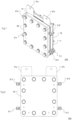
- the gas-liquid separator 1 has a liquid-side plate 20 located at the front side of the device, a gas-side plate 30 located at the rear side of the device, and a gas-liquid mixture plate 40 located between and connected to these plates, each of which is formed in a generally disk shape.
- the plates are stacked and integrally joined by fasteners such as bolts and nuts. Since the plates are integrally joined, channels are defined between the plates into each of which the multiphase fluid, the liquid separated from the multiphase fluid, and the gas separated from the multiphase fluid flow separately. Details of the channels will be described later.
- the liquid-side plate 20 has two inlet/outlet ports 41a and 41b, a liquid outlet port 21, and a gas outlet port 31 at the periphery of its flat front surface, as shown in FIGS. 1 and 2 .
- Each port has a generally cylindrical shape projecting outwardly from the surface of the liquid-side plate 20, and in this embodiment, they are arranged at equal intervals clockwise in the circumferential direction of the liquid-side plate 20 in the order of the inlet/outlet port 41a, the gas outlet port 31, the inlet/outlet port 41b, and the liquid outlet port 21.
- the gas-side plate 30 has two inlet/outlet ports 41a and 41b, a liquid outlet port 21, and a gas outlet port 31 at the periphery of its flat rear surface, as shown in FIGS. 3 and 4 .
- These ports are of the same type as the ports on the liquid-side plate 20 and are arranged on the opposite side with respect to the ports on the liquid-side plate 20.
- the same type of ports at corresponding positions on the front and rear sides of the gas-liquid separator 1, i.e., on the liquid-side plate 20 and the gas-side plate 30, may be used in pairs or only either one of them may be used.
- Each of the pair of inlet/outlet ports 41a and 41b communicates with a fluid flow channel 400 described below (see FIG. 5 ) to supply and discharge multiphase fluid to and from the device.
- the ports are connected, for example, to an unshown pump that delivers a multiphase fluid.
- the multiphase fluid is supplied through both the inlet/outlet ports 41a and 41b, and separated into gas and liquid within the device.
- the multiphase fluid may be discharged from the inlet/outlet port 41b and recirculated, or the inlet and the outlet may be reversed.
- the multiphase fluid may be supplied through either one of inlet/outlet ports 41a or 41b and the other port may be closed.
- Each of the pair of liquid outlet ports 21 communicates with a liquid flow channel 200, described below (see FIG. 5 ), located within the gas-liquid separator 1 to discharge the liquid separated from the multiphase fluid to the outside of the device.
- Each of the pair of gas outlet ports 31 communicates with a gas flow channel 300, described below (see FIG. 5 ), located within the gas-liquid separator 1 to discharge the gas separated from the multiphase fluid to the outside of the device.
- the discharged liquid and gas are each collected in a container or the like provided outside the gas-liquid separator 1.
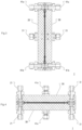
- FIG. 5 is a schematic diagram describing the internal configuration of the gas-liquid separator and the fluid flow.
- the direction of the front side of the gas-liquid separator 1 is referred to as the forward direction
- the direction of the rear side is referred to as the backward direction.
- a pair of partitions 401a and 401b formed in the shape of disks and spaced parallel to each other are provided within the gas-liquid mixture plate 40.
- a fluid flow channel 400 is defined between the pair of partitions 401a and 401b.
- the pair of partitions 401a and 401b are provided with a plurality of unshown through-holes through which the multiphase fluid may pass.
- Inflow chambers 402 and 403 into which the multiphase fluid can flow through the through-holes are defined between the partition 401a and the liquid-side plate 20 and between the partition 401b and the gas-side plate 30, respectively.
- the inflow chamber 402 is in contact at its front side with one of the surfaces of a hydrophilic membrane 52 formed in a disk-shape, that is fixed by a separator or the like, not shown in the figure, between the liquid-side plate 20 and the gas-liquid mixture plate 40.
- the inflow chamber 402 together with the fluid flow channel 400, functions as a supply channel for supplying the multiphase fluid to the hydrophilic membrane 52.
- the hydrophilic membrane 52 is a porous thin film made of a highly hydrophilic material that forms a wall of the inflow chamber 402, thereby forming a hydrophilic separation wall member for the multiphase fluid. Therefore, in this embodiment, when wetted, the hydrophilic membrane 52 allows only the liquid in the multiphase fluid to permeate and pass through. Any known material may be used for the hydrophilic membrane 52 for passing only liquids as described above.
- a liquid flow channel 200 is formed to allow the liquid that has passed through the hydrophilic membrane 52, i.e., after the gas has been separated from the multiphase fluid, to flow in and to discharge the liquid to the outside.
- the hydrophilic membrane 52 forms one of the walls of the liquid flow channel 200.
- the inflow chamber 403 is in contact at its rear side with one of the surfaces of a hydrophobic membrane 53 formed in a disk-shaped sheet, which is fixed by a separator or the like, not shown in the figure, between the gas-side plate 30 and the gas-liquid mixture plate 40.
- the inflow chamber 403, together with the fluid flow channel 400, functions as a supply channel for supplying the multiphase fluid to the hydrophobic membrane 53.
- the hydrophobic membrane 53 is a porous thin film with gas permeability that forms one of the walls of the inflow chamber 403, thereby forming a hydrophobic separation wall member for the multiphase fluid. This means that, in this embodiment, the hydrophobic membrane 53 allows only gases contained in the multiphase fluid to pass through without allowing liquids to pass through.
- Any known hydrophobic material may be used for the hydrophobic membrane 53 described above.
- An example is Gore-Tex (registered trademark) manufactured by WL Gore & Associates, Inc. from ePTFE (expanded polytetrafluoroethylene).
- the type of hydrophobic membrane 53 may be selected according to the environment in which it will be used, and may be either an organic or inorganic membrane.
- inorganic membranes include ceramic membranes such as zeolite, silica, alumina, zirconia, and titania membranes, and carbon membranes.
- organic membranes include fluoropolymer membranes such as PTFE (polytetrafluoroethylene) and PVDF (polyvinylidene fluoride) membranes, polyamide, cellulose acetate, polyimide, and polyethylene membranes.
- PTFE polytetrafluoroethylene
- PVDF polyvinylidene fluoride
- a porous material that has been made waterrepellent may be used as a hydrophobic membrane.
- a gas flow channel 300 is formed to allow the gas that has passed through the hydrophobic membrane 53, i.e., after the liquid has been separated from the multiphase fluid, to flow in and discharge the gas to the outside.
- the hydrophilic membrane 52 and the hydrophobic membrane 53 are made in the form of sheets and are arranged facing each other and separated from each other.
- the separation distance should be less than a predetermined distance.
- the separation distance may be a distance based on the size of the bubbles in the multiphase fluid. By setting the separation distance smaller than the bubble size, the gas bubbles contained in the multiphase fluid can come into contact with both the hydrophilic membrane 52 and the hydrophobic membrane 53, allowing the gas to rapidly pass into the gas flow channel 300.
- the distance should be about 1 mm to allow the multiphase fluid and the bubbles to contact the hydrophobic membrane 53.
- the fluid flow channel 400 may be formed only by the hydrophilic membrane 52 and the hydrophobic membrane 53 by removing the aforementioned partitions 401a and 401b. That is, the front wall forming the fluid flow channel 400 is the hydrophilic membrane 52 and the rear wall is the hydrophobic membrane 53.
- the multiphase fluid mainly consists of gas and is mixed, in a multiphase manner, with droplets such as water droplets, it is preferable to set the separation distance based on the droplet size in the multiphase fluid. By setting the separation distance smaller than the droplet size, the droplets contained in the multiphase fluid can come into contact with both the hydrophilic membrane 52 and the hydrophobic membrane 53, allowing the liquid to pass rapidly into the liquid flow channel 200.
- the pore diameter and the number of pores per unit area of the hydrophilic membrane 52 and the hydrophobic membrane 53 should preferably be adjusted according to the type of gas and liquid to be separated and the supply pressure of the multiphase fluid.
- the operation of the gas-liquid separator 1 of this embodiment is described below.
- the following example shows a case where a multiphase fluid is supplied to each of the paired inlet/outlet ports 41a and 41b.
- the multiphase fluid flows into the fluid flow channel 400 communicating with the inlet/outlet port 41a.
- the hatched arrow with the sign F1 in FIG. 5 indicates the flow direction of the multiphase fluid.
- the multiphase fluid that has flowed into the fluid flow channel 400 flows into the inflow chambers 402 and 403 through the through-holes in the partitions 401a and 401b.
- the multiphase fluid flowing into the inflow chambers 402 and 403 contacts both the hydrophilic membrane 52 and the hydrophobic membrane 53. At this time, the multiphase fluid flows into each membrane surface from the fluid flow channel 400 generally perpendicular to the surface, and the multiphase fluid contacts each membrane surface uniformly. Particularly for the hydrophilic membrane 52, it is preferable for the surface to be in uniform contact with the multiphase fluid because if there were dry and wet areas, gas could leak through the dry areas.
- the liquid in the multiphase fluid passes through the hydrophilic membrane 52 and flows into the liquid flow channel 200.
- the hatched arrow with the sign L in FIG. 5 indicates the direction of flow of the liquid passing through the hydrophilic membrane 52.
- the liquid flowing into the liquid flow channel 200 is discharged to the outside of the device through the pair of liquid outlet ports 21 communicating with the liquid flow channel 200.
- the gas in the multiphase fluid passes through the hydrophobic membrane 53 and flows into the gas flow channel 300.
- the hatched arrow with the sign G in FIG. 5 indicates the direction of flow of the gas passing through the hydrophobic membrane 53.
- the gas flowing into the gas flow channel 300 is discharged to the outside of the device through the pair of gas outlet ports 31 communicating with the gas flow channel 300.
- the configuration of the device may be made extremely simple and the size of the device may be reduced compared to conventional devices.
- a sheet-shaped hydrophilic membrane 52 and a hydrophobic membrane 53 are arranged to sandwich the fluid flow channel 400, wherein the liquid flow channel 200 is formed adjacent to the hydrophilic membrane 52 and the gas flow channel 300 is formed adjacent to the hydrophobic membrane 53.
- the gas-liquid separator 1 may be formed into a flat plate shape as shown in FIG.
- gas-liquid separator 1 so that it can be installed in a small space, such as a gap between apparatuses or structures, and may also be easily transported.
- a compact gas-liquid separator 1 is extremely useful in environments such as space stations, where gas-liquid separators are essential but installation space is limited, because it can operate even in a microgravity field.
- the simple configuration allows for easy maintenance and low cost.
- the gas-liquid separator of the present embodiment is easy to work with because it only requires a pump or other device to be connected to each port.
- the multiphase fluid to be separated in the gas-liquid separation was assumed to be a two-phase fluid of gas and liquid, but the multiphase fluid is not limited to such. Gas-liquid separation can even be performed for multiphase fluids having a higher phase, as long as the fluid is a liquid containing a gas.
- the gas-liquid separator of the first embodiment may be integrated into a water electrolyzer that produces hydrogen gas and oxygen gas by electrolyzing water.
- the second embodiment which is a water electrolyzer with an integrated gas-liquid separator, is described below.
- FIG. 6 is a perspective view illustrating the water electrolyzer of this embodiment.
- the water electrolyzer 1A of this embodiment is a stacked-cell type device having a plurality of electrolytic cells 10A fastened to each other with bolts and nuts, and a plurality of heat transfer pipes (heat transfer device) 12A inserted between the electrolytic cells 10A.
- the heat transfer pipes 12A are so-called heat pipes in which a heat-exchange medium flows inside to exchange heat with the outside, and when inserted between the electrolytic cells 10A, heat of the electrolytic cells in contact with the heat transfer pipes can be effectively removed.
- the number of heat transfer pipes 12A should be selected appropriately according to the size of the equipment. It should be noted that in this embodiment three electrolytic cells 10A are combined, but it is not limited thereto and two or four or more may be combined.
- the water electrolyzer 1A of this embodiment electrolyzes water into oxygen gas and hydrogen gas by means of a plurality of electrolytic cells 10A, and the configuration and operation of each electrolytic cell 10A are equivalent. Therefore, the configuration and operation of one electrolytic cell 10A will be described hereafter.
- FIGS. 7 through 10 are a perspective view, a front view, a right side view, and a left side view, respectively, illustrating the electrolytic cell of this embodiment.
- the electrolytic cell 10A comprises an end plate 60, an intermediate plate 61, an end plate 70, an intermediate plate 71, and current collector plates 81a and 81b.
- the end plates 60 and 70 are formed as square flat plates and form the front and rear walls of the electrolytic cell 10A.
- the electrolytic cell 10A is integrally formed into a generally rectangular shape by interposing the intermediate plate 61, the current collector plates 81a and 81b, and the intermediate plate 71 between the end plates 60 and 70, and fastening the end plates 60 and 70 with bolts and nuts.
- a plurality of electrolytic cells comprising intermediate plates 61 and 71 may be interposed between a pair of end plates 60 and 70.
- the intermediate plates 61 and 71 are shaped like the end plates 60 and 70, but are thicker.
- a water supply pipe 611 On the side of the intermediate plate 61 are a water supply pipe 611, a drain pipe 612 and two hydrogen discharge pipes 613.
- a water supply channel 614 Inside the intermediate plate 61 are a water supply channel 614, a drain channel 615, and a hydrogen discharge channel 616 (see FIG. 12 ), which are described in detail below.
- the water supply pipe 611 is located at the bottom of the left surface in FIG. 8 and communicates with the water supply channel 614, which supplies water to the inside of the electrolytic cell 10A.
- the drain pipe 612 is located at the top of the right surface in FIG. 8 and communicates with the drain channel 615, which discharges the water in the electrolytic cell 10A for recirculation.
- the two hydrogen discharge pipes 613 are located at the bottom of the right surface and the top of the left surface in FIG. 8 , respectively, and communicate with the hydrogen discharge channel 616.
- the two hydrogen discharge pipes 613 discharge hydrogen gas produced by electrolysis in the electrolytic cell 10A to the outside of the electrolytic cell 10A.
- Oxygen discharge pipes 711 are disposed at the bottom of the right surface and at the top of the left surface of the intermediate plate 71, as shown in FIGS. 9 and 10 .
- the oxygen discharge pipes 711 communicate with the oxygen discharge channel 712 (see FIG. 12 ), which will be described in detail later, and discharges the oxygen gas produced by electrolysis in the electrolytic cell 10A to the outside of the electrolytic cell 10A.
- FIG. 11 is an exploded side view of the electrolytic cell.
- the electrolytic cell 10A is shown disassembled in a front-to-back direction, and the O-rings 62 and 72 and the gaskets 65 and 82 are partially shown in cross-section for explanation.
- electrolytic cell 10A has, in order from the left side in FIG. 11 , that is, from the front side of the cell, end plate 60, intermediate plate 61, O-ring 62, separator 63, carbon paper 64, gasket 65, hydrophobic membrane 53, gasket 65, carbon paper 64, current collector plate 81a, gasket 82, MEA (Membrane and Electrode Assembly) 80, current collector plate 81b, O-ring 72, intermediate plate 71, and end plate 70.
- the left side with respect to MEA 80 is the hydrogen side where water is supplied and hydrogen gas is produced
- the right side with respect to MEA 80 is the oxygen side where oxygen gas is produced.
- the MEA 80 is a generally rectangular plate-shaped member formed by sandwiching and bonding a solid polymer electrolyte membrane (hereinafter referred to as the electrolyte membrane), one side of which is a hydrogen side and the other side of which is an oxygen side, between gas diffusion electrode layers from the front and rear directions. It is preferable to use proton (H+) conducting porous electrolyte membranes, such as inorganic ceramics containing titanium hydroxide nanoparticles and proton-conducting Nafion (registered trademark).
- H+ proton conducting porous electrolyte membranes
- the MEA 80 is sandwiched or fixed between the current collector plates 81a and 81b via frame-shaped gaskets 82, which are located on both sides of the MEA 80 and connected to its peripheries.
- the current collector plates 81a and 81b are plate-shaped members for electrical connection to an external power supply for supplying voltage to the MEA 80, and in FIG. 8 tabs for connection to the external power supply protrude from the top.
- each of the current collector plates 81a and 81b is configured integrally with a separator.
- a plurality of penetrating grooves, or slits, are provided through the separator of the current collector plate 81a, and in the assembled state of the electrolytic cell 10A, a water channel 811 (see FIG.
- the water channel 811 functions as a liquid supply chamber where the cathode-side electrode section is located, and water is supplied to the MEA 80.
- the water channel 811 should be shaped so that the water supplied to the MEA 80 reaches the entire electrolyte membrane surface.
- the water channel 811 communicates with the water supply pipe 611 through the water supply channel 614 formed in the intermediate plate 61, and communicates with the drain pipe 612 through the drain channel 615.
- a plurality of slits are also provided on the separator of the current collector plate 81b, and in the assembled state of the electrolytic cell 10A, an oxygen flow channel 713 (see FIG. 12 ) is formed by the plurality of slits, into which oxygen gas produced by electrolysis flows.
- the oxygen flow channel 713 is connected to the oxygen discharge channel 712 formed in the adjacent intermediate plate 71, which in turn communicates with the oxygen discharge pipe 711.
- the separator of the current collector plate 81b and the intermediate plate 71 are hermetically connected with the O-ring 72, which is an elastic member, interposed therebetween.
- a square-shaped hydrophobic membrane 53 is arranged on the front side of the current collector plate 81a.
- the hydrophobic membrane 53 is arranged facing and separated from the MEA 80, and forms a part of the wall of the liquid supply chamber formed by the water channel 811.
- the functional description of the hydrophobic membrane 53 is omitted here, as it is equivalent to that described in the first embodiment.
- the hydrophobic membrane 53 is fixed to the current collector plate 81a and the separator across the frame-shaped gaskets 65 arranged on the periphery of both sides of the hydrophobic membrane 53.
- the carbon paper 64 having gas permeability for diffusing gas and water is interposed between the hydrophobic membrane 53 and the current collector plate 81a, and through the carbon paper 64, the hydrophobic membrane 53 can contact water and hydrogen gas which is in a bubbled state in the water.
- the distance from the hydrophobic membrane 53 to the electrolyte membrane of the MEA 80, or more specifically to the catalyst layer on the cathode side is made equivalent to the separation distance described in the first embodiment.
- the separation distance is based on the bubble size of the gas produced, and should preferably be a distance at which the bubbles contact the hydrophobic membrane 53 before breaking away from the catalyst layer.
- the separation distance may preferably be about 1 mm, where both water and bubbles can contact the hydrophobic membrane 53.
- the separator 63 which is located on the front side of the hydrophobic membrane 53, is provided with a plurality of slits forming hydrogen flow channel 631 (see FIG. 12 ) through which flows hydrogen gas that has passed through the hydrophobic membrane 53.
- the hydrogen flow channel 631 of the separator 63 is connected across an O-ring 62 to the hydrogen discharge channel 616 formed in the adjacent intermediate plate 61, and through which it communicates with the hydrogen discharge pipes 613.
- Slits different from the slits forming the hydrogen flow channel 631 are formed on the separator 63, and the said slits function as water channels and connect the water flow channel formed by the water channel 811 of the separator on the current collector plate 81a to the water supply channel 614 formed on the intermediate plate 61.
- the separator 63 and the intermediate plate 61 are hermetically connected with the O-ring 62, which is an elastic member, interposed therebetween.
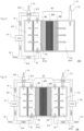
- FIG. 12 is a schematic diagram describing the internal configuration of the electrolytic cell and the flow of the fluid therein.
- the chain double-dashed lines shown in the figure illustrate the joints of the flow channels.
- the sign P1 indicates a pump, H1 indicates hydrogen gas flow direction, H2 indicates hydrogen gas bubbles, and O1 indicates oxygen gas flow direction.
- the pump P1 is connected to the water supply pipe 611 and the drain pipe 612, and supplies water to the water supply pipe 611 and receives water from the drain pipe 612 to circulate and supply water to the electrolytic cell 10A.
- the electrolytic cell 10A shall be continuously replenished with the amount of water consumed by electrolysis from an external water supply.
- water supplied through the water supply pipe 611 flows into the water channel 811 through the water supply channel 614, and the water flowing into the water channel 811 reaches the entire membrane surface of the electrolyte membrane 800 of the MEA 80.
- the water is then electrolyzed by applying a voltage to the current collector plates 81a and 81b from an external power supply connected to them.
- the hydrogen gas generated by the electrolysis at the interface between the cathode-side gas diffusion electrode layer 801 and the electrolyte membrane 800 of the MEA 80, i.e., the catalyst layer contacts the hydrophobic membrane 53 in the water channel 811 and passes therethrough to enter the hydrogen flow channel 631.
- the generated hydrogen gas passes through the gas diffusion electrode layer while diffusing through the inside of the gas diffusion electrode layer, passes through the separator and the carbon paper 64 of the current collector plate 81a, and contacts the hydrophobic membrane 53.
- the hydrogen gas in the hydrogen flow channel 631 that has passed through the hydrophobic membrane 53 is discharged from the hydrogen discharge pipe 613 through the hydrogen discharge channel 616 to the outside of the electrolytic cell 10A and collected in a collecting container or the like.
- the water in the water channel 811 that has not been electrolyzed is discharged through the drain pipe 612 to the pump P1 through the drain channel 615 and is returned to the electrolytic cell 10A.
- the hydrogen gas generated by electrolysis at the interface between the anode-side gas diffusion electrode layer 802 and the electrolyte membrane 800 of the MEA 80 flows into the oxygen flow channel 713 and is discharged from the oxygen discharge pipe 711 through the oxygen discharge channel 712 to the outside of the electrolytic cell 10A and collected in a collecting container or the like.
- the water electrolyzer 1A of this embodiment described above since the hydrophobic membrane 53 is disposed in the water channel 811, which is the cathode-side cathode chamber, the water circulates through the water channel 811, that is, between the hydrophobic membrane 53 and the MEA 80, to ensure gas-liquid separation along with electrolysis. In particular, hydrogen gas can be recovered in a good dry condition. Therefore, since the electrolytic cell is combined with a gas-liquid separation function, there is no need to prepare a separate gas-liquid separation device, and the device can be made much smaller than a water electrolyzer connected to a separate gas-liquid separator. The device can be installed in a small space, such as a gap between other devices or structures, and can also be easily transported. Such a compact water electrolyzer 1A is extremely useful in environments such as space stations, where water electrolyzers are essential but installation space is limited, because it can operate even in a microgravity field.
- the hydrogen gas generated by the MEA 80 immediately passes through the hydrophobic membrane 53 and is vented, resulting in the volume buffering effect, a situation in which only one side is pressurized as a result of gas generation can be avoided. Therefore, since there is no need to use a volume buffer device, the cost can be reduced and the size can be made smaller. In addition, since only the cathode side needs to be supplied with water, only one pump P1 is required, and the cost can be reduced and the size can be made smaller.
- the electrolytic cell 10A combined with a Sabatier reactor that produces methane (CH 4 ) and water (H 2 O) from carbon dioxide (CO 2 ) and oxygen (O 2 ) can be made into an air regenerator.
- Air regeneration is the process of recovering O 2 from CO 2 exhaled by astronauts. Specifically, the CO 2 emitted by organisms in an enclosed space is separated, concentrated, and fed into the Sabatier reactor.
- the Sabatier reaction (CO 2 + 4H 2 ⁇ CH 4 +2H 2 O) takes place, producing CH 4 and H 2 O.
- the amount of hydrogen and oxygen gases produced can be increased compared to the case of only one electrolytic cell 10A.
- the water circulation supply paths (the water supply pipe 611 and the drain pipe 612) to and from the pump P1 are connected by a manifold so as to be shared by a plurality of electrolytic cells 10A.
- the hydrogen and oxygen gas discharge paths (hydrogen discharge pipe 613 and oxygen discharge pipe 711).
- FIG. 13 is a schematic diagram describing the internal configuration and fluid flow of the electrolytic cell of the first variant embodiment.
- the sign P2 indicates a pump that is the same as P1.
- O2 indicates oxygen gas bubbles.
- the electrolytic cell 10B of FIG. 13 differs from the electrolytic cell 10A of the second embodiment in that another hydrophobic membrane 53' is also disposed on the anode side, and a water channel 812 as a second liquid supply chamber is formed between the hydrophobic membrane 53' and the MEA 80, in which an anode-side electrode section is disposed and to which water is supplied, and the pump P2 circulates water to the water channel 812.
- the hydrophobic membrane 53' is identical to the hydrophobic membrane 53, but differs in that it forms a part of a wall of the water channel 812 and passes only the oxygen gas generated by electrolysis on the anode side of the electrolyte membrane 800.
- the electrolytic cell 10B can be constructed arranging, in a mirrorsymmetrical manner with respect to the MEA 80, an intermediate plate 61, an O-ring 62, a separator 63, a carbon paper 64, a gasket 65, a hydrophobic membrane 53, another gasket 65, another carbon paper 64, and a current collector plate 81a in place of the current collector plate 81b, the O-ring 72, and the intermediate plate 71 of FIG. 11 .
- oxygen gas flows into the flow channel associated with hydrogen gas and constructed with the mirror-symmetrically arranged components. In other words, water is circulated and supplied to the anode side, and the oxygen gas that has passed through the hydrophobic membrane 53 is discharged by the mirror-symmetrically arranged components.
- the hydrophobic membrane 53' By placing the hydrophobic membrane 53' on the anode side, the same effect as on the cathode side can be obtained on the anode side, and good dry oxygen gas can be recovered. In addition, since water is supplied from both sides of the MEA 80, the heat generated in the cell by electrolysis can be dissipated more efficiently.
- FIG. 14 is a schematic diagram describing the internal configuration and fluid flow of the electrolytic cell of the second variant embodiment.
- the electrolytic cell 10C shown in FIG. 14 differs from the electrolytic cell 1A of the second embodiment in that the drain channel 615 is not provided. Therefore, the electrolytic cell 10C is a dead-end type in which the water circulation function is eliminated and all the water flowing into the water channel 811 is electrolyzed.
- the amount of water required to produce oxygen for one person by electrolysis is small, about 0. 5 grams per minute.
- conventional water electrolysis methods require pumps to circulate several liters of water to remove air bubbles from the electrodes and dissipate the heat generated there, a gas-liquid separator, and electricity to run the equipment.
- only a small amount of water e.g., 0.5 grams per minute is required for water electrolysis, and all of the supplied water can be electrolyzed.
- the pump P1 for circulating and supplying water and the gas-liquid separator device can be eliminated, and the oxygen gas generation system can be made much simpler, resulting in a more compact, lightweight and energy-saving system, as well as improved system reliability.
- the electrolytic cell 10C can be integrated with the Sabatier reactor described in the first embodiment.
- the temperature of the cells and of the Sabatier reactor was lost due to the circulation of the water.
- the reaction can be continued without lowering the temperature of the integrated Sabatier reactor.
- the heat generated in the Sabatier reactor can also be used to heat the water electrolytic cell, reducing the voltage required for electrolysis.
- the heat transfer pipes 12A may be provided in one of the intermediate plates 61 and 71 of the electrolytic cell 10C, or between the cells if the electrolytic cells 10C are stacked.
Landscapes
- Chemical & Material Sciences (AREA)
- Chemical Kinetics & Catalysis (AREA)
- Engineering & Computer Science (AREA)
- Electrochemistry (AREA)
- Materials Engineering (AREA)
- Metallurgy (AREA)
- Organic Chemistry (AREA)
- Inorganic Chemistry (AREA)
- Electrolytic Production Of Non-Metals, Compounds, Apparatuses Therefor (AREA)
- Separation Using Semi-Permeable Membranes (AREA)
- Degasification And Air Bubble Elimination (AREA)
Applications Claiming Priority (3)
| Application Number | Priority Date | Filing Date | Title |
|---|---|---|---|
| JP2021033479A JP7756389B2 (ja) | 2021-03-03 | 2021-03-03 | 気液分離装置、気液分離方法 |
| EP22763344.3A EP4260925A4 (fr) | 2021-03-03 | 2022-03-02 | Dispositif de séparation gaz-liquide, procédé de séparation gaz-liquide, dispositif d'électrolyse et procédé d'électrolyse |
| PCT/JP2022/008941 WO2022186291A1 (fr) | 2021-03-03 | 2022-03-02 | Dispositif de séparation gaz-liquide, procédé de séparation gaz-liquide, dispositif d'électrolyse et procédé d'électrolyse |
Related Parent Applications (1)
| Application Number | Title | Priority Date | Filing Date |
|---|---|---|---|
| EP22763344.3A Division EP4260925A4 (fr) | 2021-03-03 | 2022-03-02 | Dispositif de séparation gaz-liquide, procédé de séparation gaz-liquide, dispositif d'électrolyse et procédé d'électrolyse |
Publications (2)
| Publication Number | Publication Date |
|---|---|
| EP4549632A2 true EP4549632A2 (fr) | 2025-05-07 |
| EP4549632A3 EP4549632A3 (fr) | 2025-07-02 |
Family
ID=83154612
Family Applications (2)
| Application Number | Title | Priority Date | Filing Date |
|---|---|---|---|
| EP25159244.0A Pending EP4549632A3 (fr) | 2021-03-03 | 2022-03-02 | Séparateur gaz-liquide, procédé de séparation gaz-liquide, dispositif d'électrolyse et procédé d'électrolyse |
| EP22763344.3A Pending EP4260925A4 (fr) | 2021-03-03 | 2022-03-02 | Dispositif de séparation gaz-liquide, procédé de séparation gaz-liquide, dispositif d'électrolyse et procédé d'électrolyse |
Family Applications After (1)
| Application Number | Title | Priority Date | Filing Date |
|---|---|---|---|
| EP22763344.3A Pending EP4260925A4 (fr) | 2021-03-03 | 2022-03-02 | Dispositif de séparation gaz-liquide, procédé de séparation gaz-liquide, dispositif d'électrolyse et procédé d'électrolyse |
Country Status (5)
| Country | Link |
|---|---|
| US (1) | US20240011164A1 (fr) |
| EP (2) | EP4549632A3 (fr) |
| JP (2) | JP7756389B2 (fr) |
| CN (1) | CN116806278A (fr) |
| WO (1) | WO2022186291A1 (fr) |
Families Citing this family (4)
| Publication number | Priority date | Publication date | Assignee | Title |
|---|---|---|---|---|
| JP2023147271A (ja) * | 2022-03-29 | 2023-10-12 | クレイトン・ポリマーズ・ネーデルラント・ベー・フェー | 選択的透過性バリア層を有する膜電極アセンブリ |
| CN119838330B (zh) * | 2023-10-18 | 2026-01-27 | 中国石油化工股份有限公司 | 气液分离组件、气液分离装置及应用和二甲基乙烯酮的制备方法 |
| CN118223052B (zh) * | 2024-03-27 | 2024-11-19 | 清华大学 | 具有多相流直接生成功能的二氧化碳电还原反应装置 |
| JP2026007496A (ja) * | 2024-07-03 | 2026-01-16 | 三菱重工業株式会社 | 水電解セル |
Citations (1)
| Publication number | Priority date | Publication date | Assignee | Title |
|---|---|---|---|---|
| JP2002028422A (ja) | 2000-07-14 | 2002-01-29 | Tlv Co Ltd | 気液分離器 |
Family Cites Families (11)
| Publication number | Priority date | Publication date | Assignee | Title |
|---|---|---|---|---|
| JPS4636315B1 (fr) * | 1969-10-28 | 1971-10-25 | ||
| US4190426A (en) * | 1977-11-30 | 1980-02-26 | Baxter Travenol Laboratories, Inc. | Gas separating and venting filter |
| US4515606A (en) * | 1981-03-19 | 1985-05-07 | Brunswick Corporation | Gas separating and venting filter |
| US4525182A (en) * | 1983-08-29 | 1985-06-25 | Millipore Corporation | I.V. Filter apparatus |
| DE19620591B4 (de) * | 1996-05-22 | 2004-08-26 | Fresenius Medical Care Deutschland Gmbh | Vorrichtung zum Entfernen von Gasen aus Flüssigkeiten |
| US6287431B1 (en) * | 1997-03-21 | 2001-09-11 | Lynntech International, Ltd. | Integrated ozone generator system |
| US5989318A (en) * | 1998-05-19 | 1999-11-23 | International Fuel Cells Corporation | Apparatus for separating water from a two-phase stream |
| DE102009012347A1 (de) * | 2009-03-09 | 2010-09-16 | Fraunhofer-Gesellschaft zur Förderung der angewandten Forschung e.V. | Filteranordnung und ein Verfahren zur Herstellung einer Filteranordnung |
| JP2016027261A (ja) * | 2014-06-30 | 2016-02-18 | シナノケンシ株式会社 | 作動装置およびこれを用いたポンプ |
| JP3202182U (ja) * | 2015-11-06 | 2016-01-21 | 有限会社ターナープロセス | ガス生成装置 |
| CN109680290B (zh) * | 2018-12-28 | 2021-03-02 | 同济大学 | 耦合式生物电化学产氢及收集装置、系统和产氢方法 |
-
2021
- 2021-03-03 JP JP2021033479A patent/JP7756389B2/ja active Active
-
2022
- 2022-03-02 EP EP25159244.0A patent/EP4549632A3/fr active Pending
- 2022-03-02 CN CN202280008615.1A patent/CN116806278A/zh active Pending
- 2022-03-02 EP EP22763344.3A patent/EP4260925A4/fr active Pending
- 2022-03-02 WO PCT/JP2022/008941 patent/WO2022186291A1/fr not_active Ceased
- 2022-03-02 US US18/267,183 patent/US20240011164A1/en active Pending
-
2024
- 2024-12-24 JP JP2024228071A patent/JP2025036528A/ja active Pending
Patent Citations (1)
| Publication number | Priority date | Publication date | Assignee | Title |
|---|---|---|---|---|
| JP2002028422A (ja) | 2000-07-14 | 2002-01-29 | Tlv Co Ltd | 気液分離器 |
Also Published As
| Publication number | Publication date |
|---|---|
| EP4260925A1 (fr) | 2023-10-18 |
| JP7756389B2 (ja) | 2025-10-20 |
| EP4549632A3 (fr) | 2025-07-02 |
| CN116806278A (zh) | 2023-09-26 |
| JP2022134386A (ja) | 2022-09-15 |
| JP2025036528A (ja) | 2025-03-14 |
| WO2022186291A1 (fr) | 2022-09-09 |
| EP4260925A4 (fr) | 2024-08-28 |
| US20240011164A1 (en) | 2024-01-11 |
Similar Documents
| Publication | Publication Date | Title |
|---|---|---|
| EP4549632A2 (fr) | Séparateur gaz-liquide, procédé de séparation gaz-liquide, dispositif d'électrolyse et procédé d'électrolyse | |
| CN102597326B (zh) | 质子交换膜水电解槽电池模块设计 | |
| EP2300640B1 (fr) | Module électrolyseur | |
| JP2022519575A (ja) | 閉じ込められた電解質を有する電気化学システム | |
| US4729932A (en) | Fuel cell with integrated cooling water/static water removal means | |
| ES2663802T3 (es) | Disposición de células electroquímicas | |
| US20130140171A1 (en) | Electrolyser module | |
| US20230028509A1 (en) | Electrolyzer assembly comprising an insulating layer | |
| CA2819103A1 (fr) | Procede d'electrolyse et cellules d'electrolyse | |
| CN107112556B (zh) | 用于电化学电池堆的中间模块 | |
| CN119365634A (zh) | COx电解器槽流场和气体扩散层 | |
| US8864962B2 (en) | Electrolyser module | |
| JP5314273B2 (ja) | 電気分解装置及びこれを利用する燃料電池発電システム | |
| WO2009041289A2 (fr) | Système et procédé de production d'énergie de pile à combustible et procédé de fabrication correspondant | |
| CN116670871A (zh) | 用于燃料电池的加湿器的筒体和用于燃料电池的加湿器 | |
| JP2012511634A (ja) | 可燃性ガスを生成及び分離するための方法及び装置 | |
| JPH09266007A (ja) | 燃料電池 | |
| TWI917685B (zh) | 以可變電流密度及液壓差控制進行水電解之方法及電解槽 | |
| CN117926297A (zh) | 电解设备 | |
| JP2026506532A (ja) | モジュール式スタックセル構造を有する電気化学装置 | |
| HK1165511A (en) | Method and apparatus for producing and separating combustible gasses |
Legal Events
| Date | Code | Title | Description |
|---|---|---|---|
| PUAI | Public reference made under article 153(3) epc to a published international application that has entered the european phase |
Free format text: ORIGINAL CODE: 0009012 |
|
| STAA | Information on the status of an ep patent application or granted ep patent |
Free format text: STATUS: REQUEST FOR EXAMINATION WAS MADE |
|
| 17P | Request for examination filed |
Effective date: 20250320 |
|
| AC | Divisional application: reference to earlier application |
Ref document number: 4260925 Country of ref document: EP Kind code of ref document: P |
|
| AK | Designated contracting states |
Kind code of ref document: A2 Designated state(s): AL AT BE BG CH CY CZ DE DK EE ES FI FR GB GR HR HU IE IS IT LI LT LU LV MC MK MT NL NO PL PT RO RS SE SI SK SM TR |
|
| REG | Reference to a national code |
Ref country code: DE Ref legal event code: R079 Free format text: PREVIOUS MAIN CLASS: C25B0015080000 Ipc: B01D0019000000 |
|
| PUAL | Search report despatched |
Free format text: ORIGINAL CODE: 0009013 |
|
| AK | Designated contracting states |
Kind code of ref document: A3 Designated state(s): AL AT BE BG CH CY CZ DE DK EE ES FI FR GB GR HR HU IE IS IT LI LT LU LV MC MK MT NL NO PL PT RO RS SE SI SK SM TR |
|
| RIC1 | Information provided on ipc code assigned before grant |
Ipc: C25B 15/08 20060101ALI20250523BHEP Ipc: C25B 9/60 20210101ALI20250523BHEP Ipc: C25B 9/23 20210101ALI20250523BHEP Ipc: B01D 63/08 20060101ALI20250523BHEP Ipc: B01D 61/00 20060101ALI20250523BHEP Ipc: C25B 1/04 20210101ALI20250523BHEP Ipc: C25B 9/00 20210101ALI20250523BHEP Ipc: B01D 19/00 20060101AFI20250523BHEP |
|
| STAA | Information on the status of an ep patent application or granted ep patent |
Free format text: STATUS: EXAMINATION IS IN PROGRESS |
|
| 17Q | First examination report despatched |
Effective date: 20260316 |