EP4549710A1 - Elément de tuyauterie de véhicule automobile pour conduites de fluide - Google Patents
Elément de tuyauterie de véhicule automobile pour conduites de fluide Download PDFInfo
- Publication number
- EP4549710A1 EP4549710A1 EP24208189.1A EP24208189A EP4549710A1 EP 4549710 A1 EP4549710 A1 EP 4549710A1 EP 24208189 A EP24208189 A EP 24208189A EP 4549710 A1 EP4549710 A1 EP 4549710A1
- Authority
- EP
- European Patent Office
- Prior art keywords
- motor vehicle
- pipe
- outlet opening
- section
- vehicle pipeline
- Prior art date
- Legal status (The legal status is an assumption and is not a legal conclusion. Google has not performed a legal analysis and makes no representation as to the accuracy of the status listed.)
- Pending
Links
Images

Classifications
-
- F—MECHANICAL ENGINEERING; LIGHTING; HEATING; WEAPONS; BLASTING
- F01—MACHINES OR ENGINES IN GENERAL; ENGINE PLANTS IN GENERAL; STEAM ENGINES
- F01N—GAS-FLOW SILENCERS OR EXHAUST APPARATUS FOR MACHINES OR ENGINES IN GENERAL; GAS-FLOW SILENCERS OR EXHAUST APPARATUS FOR INTERNAL-COMBUSTION ENGINES
- F01N3/00—Exhaust or silencing apparatus having means for purifying, rendering innocuous, or otherwise treating exhaust
- F01N3/08—Exhaust or silencing apparatus having means for purifying, rendering innocuous, or otherwise treating exhaust for rendering innocuous
- F01N3/10—Exhaust or silencing apparatus having means for purifying, rendering innocuous, or otherwise treating exhaust for rendering innocuous by thermal or catalytic conversion of noxious components of exhaust
- F01N3/18—Exhaust or silencing apparatus having means for purifying, rendering innocuous, or otherwise treating exhaust for rendering innocuous by thermal or catalytic conversion of noxious components of exhaust characterised by methods of operation; Control
- F01N3/20—Exhaust or silencing apparatus having means for purifying, rendering innocuous, or otherwise treating exhaust for rendering innocuous by thermal or catalytic conversion of noxious components of exhaust characterised by methods of operation; Control specially adapted for catalytic conversion
- F01N3/206—Adding periodically or continuously substances to exhaust gases for promoting purification, e.g. catalytic material in liquid form, NOx reducing agents
- F01N3/2066—Selective catalytic reduction [SCR]
-
- F—MECHANICAL ENGINEERING; LIGHTING; HEATING; WEAPONS; BLASTING
- F16—ENGINEERING ELEMENTS AND UNITS; GENERAL MEASURES FOR PRODUCING AND MAINTAINING EFFECTIVE FUNCTIONING OF MACHINES OR INSTALLATIONS; THERMAL INSULATION IN GENERAL
- F16L—PIPES; JOINTS OR FITTINGS FOR PIPES; SUPPORTS FOR PIPES, CABLES OR PROTECTIVE TUBING; MEANS FOR THERMAL INSULATION IN GENERAL
- F16L43/00—Bends; Siphons
-
- F—MECHANICAL ENGINEERING; LIGHTING; HEATING; WEAPONS; BLASTING
- F01—MACHINES OR ENGINES IN GENERAL; ENGINE PLANTS IN GENERAL; STEAM ENGINES
- F01N—GAS-FLOW SILENCERS OR EXHAUST APPARATUS FOR MACHINES OR ENGINES IN GENERAL; GAS-FLOW SILENCERS OR EXHAUST APPARATUS FOR INTERNAL-COMBUSTION ENGINES
- F01N2610/00—Adding substances to exhaust gases
- F01N2610/02—Adding substances to exhaust gases the substance being ammonia or urea
-
- F—MECHANICAL ENGINEERING; LIGHTING; HEATING; WEAPONS; BLASTING
- F01—MACHINES OR ENGINES IN GENERAL; ENGINE PLANTS IN GENERAL; STEAM ENGINES
- F01N—GAS-FLOW SILENCERS OR EXHAUST APPARATUS FOR MACHINES OR ENGINES IN GENERAL; GAS-FLOW SILENCERS OR EXHAUST APPARATUS FOR INTERNAL-COMBUSTION ENGINES
- F01N2610/00—Adding substances to exhaust gases
- F01N2610/14—Arrangements for the supply of substances, e.g. conduits
-
- F—MECHANICAL ENGINEERING; LIGHTING; HEATING; WEAPONS; BLASTING
- F16—ENGINEERING ELEMENTS AND UNITS; GENERAL MEASURES FOR PRODUCING AND MAINTAINING EFFECTIVE FUNCTIONING OF MACHINES OR INSTALLATIONS; THERMAL INSULATION IN GENERAL
- F16L—PIPES; JOINTS OR FITTINGS FOR PIPES; SUPPORTS FOR PIPES, CABLES OR PROTECTIVE TUBING; MEANS FOR THERMAL INSULATION IN GENERAL
- F16L9/00—Rigid pipes
- F16L9/22—Pipes composed of a plurality of segments
Definitions
- Motor vehicle piping elements of the type mentioned above are used, for example, in the automotive sector to connect a fluid reservoir filled with a reducing agent, e.g., a urea such as AdBlue, to a supply unit designed to supply a motor vehicle exhaust tract with the urea as needed.
- a reducing agent e.g., a urea such as AdBlue
- the motor vehicle piping element as a component of a fluid line, then offers, for example, the option of arranging a supply hose and is also designed for connection to a motor vehicle exhaust tract.
- the motor vehicle piping element can also be used in any other fluid-carrying systems of a motor vehicle as a component of the fluid lines.
- both the flow behavior and the volume flow are determined by the internal cross-section of the automotive piping element.
- the volume resulting from the internal cross-section also determines, in the case of the automotive piping element being used to supply reducing agents in the vehicle, how much reducing agent remains in the motor vehicle piping element after a shutdown process.
- the reducing agent remaining in the motor vehicle piping element must be sucked out of the motor vehicle piping element after the motor vehicle is switched off.
- the known design of the motor vehicle piping elements results in a reduction of the internal volume of the motor vehicle piping element provided by the outer pipe by inserting the inner pipe body into the outer pipe, whereby at the same time, by maintaining the inner cross-section of the outer pipe in the area of the buffer section, a sufficiently large storage space is created, which is suitable for keeping a required amount of liquid, e.g. a reducing agent, on demand.
- the invention is based on the object of providing a motor vehicle pipeline element of the type mentioned at the outset with a bending section which enables reliable use.
- the inventive design of the motor vehicle pipe element with an at least two-part inner pipe body makes it possible to provide the motor vehicle pipe element with a desired bending section in the region of the two pipe body elements after an arrangement of the inner pipe body comprising at least two pipe body elements, without this resulting in a structural weakening of the outer pipe in the form of bulges or tapering of the outer pipe, which promote crack formation and can lead to failure of the motor vehicle pipe element.
- the inventive division of the inner pipe body into at least two pipe body elements ensures, compared to the one-piece inner pipe bodies known from the prior art, that during the manufacture of the bending section, no damaging influences from the inner pipe body act on the outer pipe body when the motor vehicle pipe element is bent.
- the motor vehicle pipeline element according to the invention is thus characterized in that, while maintaining the inner cross-section of the outer pipe in some sections to form a buffer section and using an inner pipe body to reduce the internal volume, the motor vehicle pipeline element has sufficient stability even when producing a bent section. Failure of the motor vehicle pipeline element during operation due to structural weaknesses in the area of the bent section is thus effectively prevented.
- the inner pipe body has two pipe body elements which, after the creation of a bend in the motor vehicle pipe element, are arranged with mutually facing end faces in the region of the bent section.
- This embodiment of the invention ensures in a particularly reliable manner that the pipe body elements do not exert any effects on the outer pipe that could weaken the structure of the motor vehicle pipe element during the production of the bent section.
- Corresponding negative influences are prevented by the fact that the mutually facing end faces of the first and second pipe body elements can change their distance from one another during the production of the bent section, wherein after the production of the bent section, the distance between the end faces from one another - viewed transversely to the longitudinal axis direction of the pipe body element - varies.
- the first pipe body element has a second end face facing the second pipe body element and a first end face facing the outlet opening, wherein the first end face is oriented perpendicular to the inner wall of the inner pipe. Due to this embodiment of the invention, the first end face of the first pipe body element forms a surface extending perpendicular to the inner wall, whereby the size of the buffer storage can be determined and fixed in a particularly simple manner. Furthermore, this embodiment of the invention ensures the formation of a substantially cylindrical buffer storage, which particularly reliably ensures a sufficient supply of liquid arranged in the buffer storage when needed.
- the inner pipe body is inserted into a cylindrical, bent pipe before the bend is made and placed at a predetermined location.
- the first and second end faces of the first tubular body element and/or the third and fourth end faces of the second tubular body element are aligned perpendicular to the inner wall of the inner tube before the bent section is produced.
- This embodiment of the invention enables particularly precise positioning and alignment of the tubular body elements relative to one another and within the outer tube.
- the second end face of the first tubular body element and the third end face of the second tubular body element facing the first tubular body element are arranged at a distance from one another before the production of the bent section. This particularly advantageously ensures that the first tubular body element and the second tubular body element are arranged at a distance from one another during the production of the bent section and also after the production of the bent section, so that they do not exert any structurally damaging effects on the outer tube, possibly due to interaction.
- the motor vehicle pipeline element is fundamentally suitable for being connected as a component of a liquid conveying line with other elements of the liquid conveying line.
- the motor vehicle pipeline element can be designed with suitable connecting elements that enable a liquid-tight connection with corresponding connecting elements.
- the pipeline element can also be used to be connected to a section of a hose line, wherein the hose line is guided over the outer pipe for this purpose.
- the outer pipe has a taper in the area of the inlet opening and/or in the area of the The outlet opening has a circumferential flange.
- the outer tube has a bead running around its outside, which is particularly preferably formed by plastic deformation of the outer tube, in particular by upsetting the outer tube.
- a bead running around its outside enables a particularly reliable arrangement of a hose element, which can be positively locked behind the bead, in particular in the sliding direction of the hose element.
- the bead thus makes the connection of a hose element to a motor vehicle pipeline element particularly reliable, and the bead can, in principle, be produced in any desired manner.
- the bead can be formed by applying material to the outer surface of the outer tube.
- the bead is formed by plastic deformation of the outer tube, in particular by upsetting the outer tube. This offers the advantage that a connection of a separate bead element to the outer tube can be dispensed with. Upsetting also represents a particularly simple and cost-effective manufacturing process.
- a possible disadvantage of the upsetting process which leads to a constriction in the corresponding area on the inside of the outer tube due to the deformation, is also avoided in the motor vehicle pipeline element according to the invention in that, with a suitable design of the inner tube body, the constriction has no effect on the flow channel if the upsetting is arranged in the area of the connecting section of the outer tube.
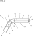
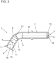
- Figure 1 shows a motor vehicle pipeline element 1 before the formation of a bending section 8 (cf. Figure 2 ) and the final formation of a flange 15 in the area of an outlet opening 4 (cf. Figure 3 ) for providing a motor vehicle pipeline element 1 adapted to the intended use.
- the motor vehicle pipeline element 1 is formed from an outer pipe 2, which extends from an inlet opening 3 to an outlet opening 4, and an inner pipe body 5 formed from a first pipe body element 9 and a second pipe body element 10.
- the first pipe body element 9 and the second pipe body element 10 are inserted into the outer pipe 2 and are in the Figure 1 shown, which has no bending section, are arranged at a distance from one another, so that the inner tube body 5 has a gap in the area between a second end face 12 of the first tube body element 9 and a third end face 13 of the second tube body element 10.
- the motor vehicle pipeline element 1 To adapt the motor vehicle pipeline element 1 to its intended use, it is bent to produce a bent section 8, with the first pipe body element 9 and the second pipe body element 10 being arranged in sections in the region of the bent section 8. Due to the spacing of the first pipe body element 9 and the second pipe body element 10 in the region of the bent section 8, these do not exert any influences on the outer pipe 2 that could weaken the structure of the outer pipe 2 during the production of the bent section 8.
- a flange 15 is formed in the region of the outlet opening of the outer pipe 2, so that the motor vehicle pipeline element 1 can be reliably arranged on a component to be connected by means of the flange 15.
- the outer tube 2 has a taper 16, which allows the arrangement of a hose (not shown here), so that liquid passes through the inlet opening 3 into an inlet opening 6 of the second tubular body element 10, which has its fourth end face 14 arranged in the area of the outlet opening 4.
- the liquid flows through the inner tube body 5 and exits from the inner tube body 5 in the area of the first end face 11 through the outlet opening 7. Due to the spaced arrangement of the first end face 11, the liquid passes from the outlet opening 4 into a buffer storage 18, which has a larger cross-section than the inner tube body 5, namely formed by the inner wall of the outer tube 2.
- the outer pipe 2 further comprises a bead 17 formed by compression, to which a hose can be fixed to the motor vehicle pipe element 1.
Landscapes
- Engineering & Computer Science (AREA)
- General Engineering & Computer Science (AREA)
- Chemical & Material Sciences (AREA)
- Mechanical Engineering (AREA)
- Chemical Kinetics & Catalysis (AREA)
- Health & Medical Sciences (AREA)
- Toxicology (AREA)
- Combustion & Propulsion (AREA)
- Rigid Pipes And Flexible Pipes (AREA)
Applications Claiming Priority (1)
| Application Number | Priority Date | Filing Date | Title |
|---|---|---|---|
| DE102023130098.9A DE102023130098B3 (de) | 2023-10-31 | 2023-10-31 | Kraftfahrzeugrohrleitungselement für Flüssigkeitsleitungen |
Publications (1)
| Publication Number | Publication Date |
|---|---|
| EP4549710A1 true EP4549710A1 (fr) | 2025-05-07 |
Family
ID=92422716
Family Applications (1)
| Application Number | Title | Priority Date | Filing Date |
|---|---|---|---|
| EP24208189.1A Pending EP4549710A1 (fr) | 2023-10-31 | 2024-10-22 | Elément de tuyauterie de véhicule automobile pour conduites de fluide |
Country Status (2)
| Country | Link |
|---|---|
| EP (1) | EP4549710A1 (fr) |
| DE (1) | DE102023130098B3 (fr) |
Citations (3)
| Publication number | Priority date | Publication date | Assignee | Title |
|---|---|---|---|---|
| EP0681131A1 (fr) * | 1994-05-04 | 1995-11-08 | Continental Aktiengesellschaft | Section courbée d'un tuyau souple |
| US20050241714A1 (en) * | 2004-04-30 | 2005-11-03 | Barnhouse James P | Apparatus and method for shaping hose |
| DE102017127305A1 (de) * | 2017-11-20 | 2019-05-23 | AT-Tec Attendorner Tube-Tec GmbH | Rohrleitungselement für Flüssigkeitsleitungen |
Family Cites Families (1)
| Publication number | Priority date | Publication date | Assignee | Title |
|---|---|---|---|---|
| JP2007040474A (ja) | 2005-08-04 | 2007-02-15 | Nissan Motor Co Ltd | 脈動吸収装置 |
-
2023
- 2023-10-31 DE DE102023130098.9A patent/DE102023130098B3/de active Active
-
2024
- 2024-10-22 EP EP24208189.1A patent/EP4549710A1/fr active Pending
Patent Citations (3)
| Publication number | Priority date | Publication date | Assignee | Title |
|---|---|---|---|---|
| EP0681131A1 (fr) * | 1994-05-04 | 1995-11-08 | Continental Aktiengesellschaft | Section courbée d'un tuyau souple |
| US20050241714A1 (en) * | 2004-04-30 | 2005-11-03 | Barnhouse James P | Apparatus and method for shaping hose |
| DE102017127305A1 (de) * | 2017-11-20 | 2019-05-23 | AT-Tec Attendorner Tube-Tec GmbH | Rohrleitungselement für Flüssigkeitsleitungen |
Also Published As
| Publication number | Publication date |
|---|---|
| DE102023130098B3 (de) | 2024-09-05 |
Similar Documents
| Publication | Publication Date | Title |
|---|---|---|
| EP2281138B1 (fr) | Coude tubulaire à écoulement optimisé | |
| DE2417640A1 (de) | Rohranschlussverbindung | |
| DE3602499A1 (de) | Kupplungsnippel | |
| EP2412964A1 (fr) | Tube ondulé d'une conduite de carburant | |
| EP3921551B1 (fr) | Équerre de liaison par communication fluidique de conduits de fluide d'un véhicule | |
| DE10143511B4 (de) | Speichereinspritzsystem mit Drosseleinrichtung | |
| EP2304305B1 (fr) | Raccord réducteur de tube en un matériau plastique | |
| DE69707379T2 (de) | Dampfauslassanordnung | |
| DE102010014573A1 (de) | Verfahren zur Herstellung eines Fahrzeugschalldämpfers und Fahrzeugschalldämpfer | |
| DE102023130098B3 (de) | Kraftfahrzeugrohrleitungselement für Flüssigkeitsleitungen | |
| WO2017193224A1 (fr) | Conduite haute pression | |
| DE102009001564B4 (de) | Drosselelement | |
| DE8226854U1 (de) | Schlauchfoermiges, verformbares verbindungselement | |
| DE102024105606A1 (de) | Rohrkörper | |
| EP3486539B1 (fr) | Élément de tuyauterie de carburant pour conduites du liquide | |
| DE102018102934A1 (de) | Axialkugelzapfen | |
| AT3651U1 (de) | Füllrohr für den kraftstofftank eines kraftfahrzeuges | |
| DE112020006247T5 (de) | Harzanschlussstück, Kanalblock und Fluidsteuervorrichtung | |
| DE10143805B4 (de) | Bolzenführungseinheit für eine Schwimmsattel-Scheibenbremse | |
| DE69809823T3 (de) | Verfahren zum Verbinden eines Schlauches mit einem Rohr, Kupplung und Befestigungsring zum Durchführen dieses Verfahrens | |
| DE102018115689A1 (de) | Mischvorrichtung zur Einmischung eines Fluids in einen Abgasmassenstrom | |
| DE29608289U1 (de) | Vorrichtung zum Mischen von Strömungsmedien | |
| DE102019133972B3 (de) | Schlauch-konnektor-verbindung | |
| DE102021112375A1 (de) | Vorrichtung zur Injektion von Kraftstoff, die einen Düseneinsatz beinhaltet | |
| DE102023117145A1 (de) | Sprühdüse, Anordnung mit einer Sprühdüse und Verfahren zum Herstellen einer Sprühdüse |
Legal Events
| Date | Code | Title | Description |
|---|---|---|---|
| PUAI | Public reference made under article 153(3) epc to a published international application that has entered the european phase |
Free format text: ORIGINAL CODE: 0009012 |
|
| STAA | Information on the status of an ep patent application or granted ep patent |
Free format text: STATUS: REQUEST FOR EXAMINATION WAS MADE |
|
| 17P | Request for examination filed |
Effective date: 20250401 |
|
| AK | Designated contracting states |
Kind code of ref document: A1 Designated state(s): AL AT BE BG CH CY CZ DE DK EE ES FI FR GB GR HR HU IE IS IT LI LT LU LV MC ME MK MT NL NO PL PT RO RS SE SI SK SM TR |