EP4549822A1 - Procédé de fonctionnement d'une installation de chauffage, installation de chauffage et programme informatique - Google Patents
Procédé de fonctionnement d'une installation de chauffage, installation de chauffage et programme informatique Download PDFInfo
- Publication number
- EP4549822A1 EP4549822A1 EP24210458.6A EP24210458A EP4549822A1 EP 4549822 A1 EP4549822 A1 EP 4549822A1 EP 24210458 A EP24210458 A EP 24210458A EP 4549822 A1 EP4549822 A1 EP 4549822A1
- Authority
- EP
- European Patent Office
- Prior art keywords
- circuit
- heating
- volume flow
- heat generator
- heating circuit
- Prior art date
- Legal status (The legal status is an assumption and is not a legal conclusion. Google has not performed a legal analysis and makes no representation as to the accuracy of the status listed.)
- Pending
Links
Images

Classifications
-
- F—MECHANICAL ENGINEERING; LIGHTING; HEATING; WEAPONS; BLASTING
- F24—HEATING; RANGES; VENTILATING
- F24D—DOMESTIC- OR SPACE-HEATING SYSTEMS, e.g. CENTRAL HEATING SYSTEMS; DOMESTIC HOT-WATER SUPPLY SYSTEMS; ELEMENTS OR COMPONENTS THEREFOR
- F24D19/00—Details
- F24D19/10—Arrangement or mounting of control or safety devices
- F24D19/1006—Arrangement or mounting of control or safety devices for water heating systems
- F24D19/1009—Arrangement or mounting of control or safety devices for water heating systems for central heating
- F24D19/1015—Arrangement or mounting of control or safety devices for water heating systems for central heating using a valve or valves
-
- F—MECHANICAL ENGINEERING; LIGHTING; HEATING; WEAPONS; BLASTING
- F24—HEATING; RANGES; VENTILATING
- F24D—DOMESTIC- OR SPACE-HEATING SYSTEMS, e.g. CENTRAL HEATING SYSTEMS; DOMESTIC HOT-WATER SUPPLY SYSTEMS; ELEMENTS OR COMPONENTS THEREFOR
- F24D19/00—Details
- F24D19/10—Arrangement or mounting of control or safety devices
- F24D19/1006—Arrangement or mounting of control or safety devices for water heating systems
- F24D19/1009—Arrangement or mounting of control or safety devices for water heating systems for central heating
- F24D19/1012—Arrangement or mounting of control or safety devices for water heating systems for central heating by regulating the speed of a pump
-
- F—MECHANICAL ENGINEERING; LIGHTING; HEATING; WEAPONS; BLASTING
- F24—HEATING; RANGES; VENTILATING
- F24D—DOMESTIC- OR SPACE-HEATING SYSTEMS, e.g. CENTRAL HEATING SYSTEMS; DOMESTIC HOT-WATER SUPPLY SYSTEMS; ELEMENTS OR COMPONENTS THEREFOR
- F24D19/00—Details
- F24D19/10—Arrangement or mounting of control or safety devices
- F24D19/1006—Arrangement or mounting of control or safety devices for water heating systems
- F24D19/1009—Arrangement or mounting of control or safety devices for water heating systems for central heating
- F24D19/1015—Arrangement or mounting of control or safety devices for water heating systems for central heating using a valve or valves
- F24D19/1036—Having differential pressure measurement facilities
-
- F—MECHANICAL ENGINEERING; LIGHTING; HEATING; WEAPONS; BLASTING
- F24—HEATING; RANGES; VENTILATING
- F24D—DOMESTIC- OR SPACE-HEATING SYSTEMS, e.g. CENTRAL HEATING SYSTEMS; DOMESTIC HOT-WATER SUPPLY SYSTEMS; ELEMENTS OR COMPONENTS THEREFOR
- F24D3/00—Hot-water central heating systems
- F24D3/18—Hot-water central heating systems using heat pumps
-
- F—MECHANICAL ENGINEERING; LIGHTING; HEATING; WEAPONS; BLASTING
- F24—HEATING; RANGES; VENTILATING
- F24H—FLUID HEATERS, e.g. WATER OR AIR HEATERS, HAVING HEAT-GENERATING MEANS, e.g. HEAT PUMPS, IN GENERAL
- F24H15/00—Control of fluid heaters
- F24H15/20—Control of fluid heaters characterised by control inputs
- F24H15/242—Pressure
Definitions
- the invention relates to a method for operating a heating system, a heating system and a computer program.
- Heating systems typically have one or more heating circuits to heat or cool the rooms they supply.
- Various options are available for implementing multiple heating circuits within a heating system.
- the appropriate heat transfer medium flow rate can be set independently and separately for each heating circuit.
- hydraulic decoupling is complex; for example, a system with one heat generator circuit and two heating circuits requires a hydraulic separator, three circulation pumps, and at least one flow rate sensor.
- a heating system with two heating circuits and one heat generator circuit requires only one overflow valve, two circulation pumps, and two flow rate sensors. Hydraulic balancing in such systems can be achieved using the overflow valve. Two dedicated flow rate sensors are required for status detection, i.e., the distribution of heat transfer fluid flow rates between the two heating circuits, because the heating circuits influence each other.
- an overflow valve is a mechanical and statically adjustable component that cannot respond to dynamic, variable heat demand. Furthermore, an overflow valve must be manually adjusted and thus positioned within the heater so that it is accessible from the outside, which limits the design freedom of a heater. Last but not least, an overflow valve can become clogged or fail, which is associated with high (maintenance) costs.
- the invention should not increase the complexity of a heating system and require only minor structural changes, and possibly also reduce the necessary installation work for a heating system.
- steps a) and b) are carried out at least once in the specified order.
- Step a) can be carried out at least once after commissioning of the heating system and serves to determine the required differential pressure for the design case.
- Step a) can also be repeated periodically or as needed.
- Step b) is used to adjust/find a first setting position of the balancing valve, in which the volume flow delivered by the first circulation pump is distributed between the first and second heating circuits according to the design state.
- the proposed method serves for a particularly precise and energy-efficient operation of a heating system according to the generic term.
- the heating system can heat or cool a building.
- the heating system can be connected to a heating circuit in which a heat transfer medium can circulate.
- the heat transfer medium can, in particular, be heating water.
- the heating system can include a heat generator that can transfer heat to or extract heat from a heat generator circuit.
- the heat generator may, in particular, be a heat pump capable of heating or cooling the heat carrier circulating in the heat generator circuit.
- the heat generator may also be a heating device designed to Combustion of a fuel.
- the fuel to be burned can be, for example, natural gas or hydrogen.
- the heat generator circuit of the heating system can have a first circulation pump that can pump the heat transfer medium.
- a volume flow sensor can also be present to measure the volume flow of heat transfer medium pumped in the heat generator circuit.
- the flow of the heat generator circuit can be connected to a flow of a first heating circuit and to the flow of a second heating circuit.
- the return of the heat generator circuit can be connected to a return of the first heating circuit and a return of the second heating circuit.
- the first heating circuit and the second heating circuit are two heating circuits arranged in parallel.
- Heat consumers such as radiators or surface heating systems can be arranged in the first and second heating circuits.
- one or more radiators controlled by a thermostatic valve can be arranged in the first heating circuit, which can also be referred to as a direct heating circuit.
- at least one surface heating system can be present in the second heating circuit, which can also be referred to as a mixed heating circuit.
- the first heating circuit can exclusively contain radiators controlled by a thermostatic valve, and the second heating circuit can exclusively contain one or more surface heating systems.
- the second heating circuit also contains a balancing valve that can be controlled electrically or electronically and moved by an actuator into a setting position of the balancing valve, which ranges, in particular continuously, from complete closing to complete opening of the balancing valve.
- the electrically controllable balancing valve can be connected to a process-executing device, such as a control and regulation device.
- the second heating circuit also includes a three-way mixing valve that can flow through a bypass located between the flow and return of the second heating circuit.
- the three-way mixing valve can therefore set a flow temperature of the second heating circuit.
- the three-way mixing valve can also be electrically or electronically controlled and connected to a process-executing device such as a control unit.
- the second heating circuit includes a temperature sensor for detecting a flow temperature of the second heating circuit, which enables the flow temperature set by the three-way mixing valve to be detected.
- the second heating circuit can include a second circulation pump configured to circulate the heat transfer medium in the second heating circuit.
- the balancing valve can be arranged upstream of the three-way mixing valve, and the three-way mixing valve can be arranged upstream of the temperature sensor for measuring the flow temperature.
- the second circulation pump can be arranged downstream of the three-way mixing valve in the flow direction.
- the first and/or second circulation pump can, in particular, be a controllable circulation pump, which can also be connected to the control unit as a process-executing device.
- the first circulation pump can be configured to output a generated differential pressure, for example, via a data transmission connection.
- the transmission can, for example, be made to a control unit that executes the process.
- the heating system is therefore a system without hydraulic decoupling with two parallel heating circuits, which is underdetermined in terms of measurement technology.
- a necessary first differential pressure can be determined, which is required to operate the first heating circuit in the design state.
- the first differential pressure indicates a differential pressure (a residual head) that is necessary to operate the first heating circuit in the design state.
- a first setting position of the balancing valve corresponding to the first differential pressure this results in a volume flow in the first heating circuit corresponding to the design state, which, with a specified temperature spread between the supply and return lines, can transfer the heat flow required for supply and thus meet the heating requirement in the first heating circuit.
- the volume flow in the second heating circuit can be adjusted by the dedicated second circulation pump (circulation pump) and the three-way mixing valve or bypass, independently of the volume flow flowing through the balancing valve.
- the volume flow flowing through the balancing valve must be at least large enough to provide a sufficient heat flow in the design state with the three-way mixing valve fully open (and thus the bypass closed).
- the required heat flows and the associated required volume flows may have been determined in advance as part of a heating load calculation.
- the balancing valve in particular, may be completely closed.
- design state refers to a state in which the heating system must transfer maximum heat and, therefore, all consumers are fully open.
- the required flow rates in the first and second heating circuits should be set when performing steps a) and b) by adjusting the balancing valve and thus by dividing the flow rate of the heat generator circuit between the first and second heating circuits.
- a heating system When planning a heating system, it should be designed to ensure that the heating system is sufficiently dimensioned to supply a building. This usually involves taking into account data relating to the specific climatic conditions at the location and the structural requirements of the specific building/the specific rooms to be supplied. During the design process, for example, a nominal output of a heat generator and the size of a consumer (convector, radiator, underfloor heating, etc.) for each room to be supplied can be determined in order to ensure a reliable supply of the building by the heating system. Based on the design of the heating system (in particular its dimensions, equipment and/or operating mode), a specified heating and/or cooling output can be set or ensured under the predetermined conditions.
- a (maximum) output of a heat generator can be determined and the consumers to be connected via a heating circuit (radiators, convectors, surface heating (underfloor or wall heating elements)) can be dimensioned in order to ensure a reliable heat supply under the specific climatic conditions at the location and the structural characteristics of the building to be supplied (particularly its thermal insulation).
- a heating circuit radiatators, convectors, surface heating (underfloor or wall heating elements)
- Various design methods are known. For example, the specific wall, window, ceiling and/or floor areas for each room to be supplied can be used to determine the specific (output) requirement and then select a specific consumer (e.g. radiators).
- the floor area of all rooms to be supplied and approximate information on the structural characteristics of the building can be taken into account to determine the requirement and dimension the heating system.
- the design state is characterized by the maximum heat flow to be transferred, with which the building or the rooms to be supplied can be heated to a specified temperature.
- a temperature spread between the flow and return of the heat generator circuit as well as a second target volume flow for the heat generator circuit and/or a first target volume flow for the first heating circuit can be specified.
- the second target volume flow in the heat generator circuit can be made up of the (target) volume flow in the first and second heating circuits and the volume flow that flows via the bypass of the second heating circuit:
- the second target volume flow can take the heat requirement of the second heating circuit into account and the second heating circuit can be operated in a self-regulating manner.
- the second circulating pump can be operated to regulate the differential pressure and a flow temperature can be regulated/set via the three-way mixing valve.
- the process steps a1) to e1) can be carried out at least once in the specified order.
- the balancing valve can be completely closed. This closes the flow of the second heating circuit, and the entire volume flow of the heat generator circuit flows through the first heating circuit.
- a predetermined first target volume flow of the design state for the first heating circuit can be regulated by means of the first circulation pump and the volume flow sensor in the heat generator circuit.
- a first pump operating parameter of the first circulation pump can be detected, which is characteristic of the pump operating state adjusted in step b1).
- the first pump operating parameter can, in particular, be a PWM signal with which the first circulation pump is controlled, or a pump speed.
- the detected first pump operating parameter is thus characteristic of the first target volume flow adjusted in step b1) with the balancing valve fully closed.
- a first pump differential pressure (a delivery head) of the first circulation pump for the first pump operating parameter determined in step c1) can be determined using a predefined pump characteristic.
- the predefined pump characteristic can be a predefined pump characteristic curve that establishes a relationship between the pumped volume flow, the generated pump differential pressure, and the pump operating parameter (a PWM signal or a pump speed).
- the first pump differential pressure is thus determined at the time at which the pump operating state of step b1) was adjusted.
- the first pump differential pressure of the first circulation pump refers to the pressure difference generated by it between the flow and return in the heat generator circuit at a time when the pump operating state of step b1) has been adjusted.
- the pump differential pressure is made up of the pressure drop in the heat generator circuit and the first differential pressure required to operate the first heating circuit in the design state, or represents a sum of both in the steady state.
- the pressure drop in the heat generator circuit is given by a predetermined pressure loss characteristic, so that in step e1) the first differential pressure (residual delivery head) for operating the first heating circuit in the design state can be determined.
- the first differential pressure dp in the design state can be used to determine the hydraulic resistance R hyd of the first heating circuit.
- Steps a2) and b2) can, in particular, be carried out in parallel and identically. Steps a2) and b2) can be carried out continuously in order to operate the heating system in the design state. If a largely steady state has been established during the execution of steps a2) and b2), according to one embodiment, a first setting position of the circuit regulating valve and, if applicable, the hydraulic resistance of the first heating circuit can be recorded and, if applicable, stored and/or stored in a control system. For example, the first setting position can be stored in a memory of a control and regulation device executing the process.
- a predetermined second target volume flow in the heat generator circuit can be adjusted using the heat generator circuit's volume flow sensor and the first circulation pump.
- the second target volume flow can correspond to the target volume flow of the heat generator circuit in the design state.
- the differential pressure determined in step a) can be adjusted at the specified first target flow rate, with the opening position of the balancing valve serving as a control variable.
- the balancing valve (which is closed after performing steps a1) to e1) is opened until the differential pressure determined in step a) is set.
- the pressure loss of the first heating circuit should be greater than the pressure loss of the second heating circuit with the balancing valve fully open.
- a first setting position is now set on the circuit regulating valve; with the set target volume flow of the design state in the heat generator circuit, the desired volume flows necessary for heat supply in accordance with the design state can be set in the first and second heating circuits.
- steps a) and b) or a1) to e1) as well as a2) and b2) can be carried out entirely with computer support. Adjusting an overflow valve is thus unnecessary, and in fact, the presence of an overflow valve can be advantageously dispensed with entirely.
- the first circulation pump when carrying out step b), can be adjusted to a target volume flow by means of the volume flow sensor and the second heating circuit can be adjusted to a constant, predetermined flow temperature and a constant predetermined volume flow by means of the second circulation pump, the three-way mixing valve and the temperature sensor, which is configured to detect a flow temperature of the second heating circuit.
- radiators with a thermostatic valve are arranged in the first heating circuit
- operating the valve with a constant, regulated differential pressure is particularly advantageous, since even after individual thermostatic valves are closed, the remaining open radiators are each operated with a constant flow rate.
- radiators arranged in the first heating circuit are always supplied with the same flow rate even after one or more thermostatic valves are closed.
- hydraulic balancing of the radiators arranged in the first heating circuit can ensure that the desired flow rate is achieved in each (open) radiator at a constant differential pressure.
- This flow rate can This corresponds to the volume flow of the heating load calculation (the design), which, at a given temperature difference between the flow and return, provides a volume flow corresponding to the heating load in the design state. If the first heating circuit were operated with a constant volume flow, closing individual thermostatic valves would lead to an increase in the volume flow in the remaining open radiators, which could be accompanied by unpleasant noise.
- the first circulation pump can regulate a constant volume flow of the design state using the volume flow sensor
- the second heating circuit can be regulated to a constant, predetermined flow temperature in the second heating circuit using the second circulation pump, the three-way mixing valve, and a temperature sensor configured to detect a flow temperature of the second heating circuit.
- the volume flow to be regulated can be reduced as needed, and the balancing valve can remain in the first setting position.
- the flow pumped by the first circulation pump can The volume flow can be reduced as needed.
- regulation of the pressure difference with the circuit regulating valve as the actuator is ended and the circuit regulating valve is moved to the first setting position and left there. This can advantageously meet a reduced heat demand.
- a heat pump as the heat generator could detect the decreasing temperature difference between the supply and return lines and reduce the value of the target volume flow to be adjusted in order to increase the temperature difference.
- a lower return temperature can lead to a lower condensation temperature in the condenser, which can have a positive effect on the efficiency of the heat pump.
- the absolute value of the volume flow in the heat generator circuit as well as in the first and second heating circuits would decrease.
- the distribution of the volume flow from the heat generator circuit to the first and second heating circuits remains approximately constant.
- the volume flow in the heat generator circuit can be reduced as needed, and based on the subsequently reduced volume flow in the first heating circuit, a required second differential pressure can be determined using the largely constant hydraulic resistance of the first heating circuit, and the circuit regulating valve can be controlled to the second differential pressure.
- This can represent a more comprehensive control strategy that uses the volume flow proportionally reduced in the first heating circuit when the volume flow in the heat generator circuit is reduced. With this reduced volume flow setpoint of the first heating circuit, a new required second differential pressure can be determined using the hydraulic resistance approach described above, at which the reduced volume flow in the first heating circuit will occur.
- Steps a3) to c3) can be performed at least once in the specified order.
- the first heating circuit should be completely blocked.
- a corresponding zone valve could, for example, be closed automatically.
- the balancing valve should be opened sufficiently to ensure that the minimum flow rate can be delivered at the maximum speed (power) of the first circulation pump.
- the second setting position of the balancing valve is known, which can ensure the circulation of a minimum flow rate in the heating circuits.
- the minimum flow rate is particularly necessary to be able to react when heating requirements are detected, for example by opening a thermostatic valve, to be able to cope with a sudden drop in the return temperature by extracting heat, and also to create a possibility for extracting heat from the heating system.
- a heating system which comprises means for carrying out a method proposed here.
- the heating system can also have a heat generator circuit with a first circulation pump and a volume flow sensor.
- the heat generator circuit can also be provided with a first heating circuit and a second heating circuit.
- a second circulation pump and a 3-way mixing valve can be installed in the second heating circuit, which can flow through a bypass between the flow and return of the second heating circuit.
- a balancing valve and a temperature sensor for detecting a flow temperature of the second heating circuit can be installed in the second heating circuit.
- a control and regulating device in particular of a heating system, configured to carry out a method presented here.
- the control and regulating device can, for example, have or have a processor.
- the processor can, for example, execute the method stored in a memory (of the control and regulating device).
- Data necessary for carrying out a method proposed here for example data of the design state, a pump characteristic curve of the first circulating pump, a pressure loss characteristic of the heat generator circuit, as well as data acquired during the implementation of the method, such as a first and second setting position of the circuit regulating valve and a recorded or determined differential pressure, can advantageously also be stored in the memory (of the control and regulating device).
- a computer program (product) is also proposed, comprising instructions that cause a computer to perform a method presented here.
- the computer program can, in particular, perform all or part of the proposed method steps.
- the computer program may establish a connection to a network, such as the Internet, and/or a data connection to a mobile device and/or to a (regulation and control device) of an air conditioning unit.
- a network such as the Internet
- a data connection to a mobile device and/or to a (regulation and control device) of an air conditioning unit.
- volume flow this refers to a flow rate.
- mass flow which can be converted into a volume flow, and vice versa, given the density and temperature of the circulating heat transfer medium.
- first primarily serve (only) to distinguish between several similar objects, quantities, or processes, and therefore do not necessarily specify any interdependence and/or sequence of these objects, quantities, or processes. Should a dependence and/or sequence be required, this is explicitly stated here or will be obvious to the person skilled in the art upon studying the specifically described embodiment. To the extent that a component can occur multiple times (“at least one"), the description of one of these components may apply equally to all or part of the majority of these components, but this is not mandatory.
- a method for operating a heating system, a computer program, a control device, and a heating system are provided that at least partially solve the problems described with reference to the prior art.
- the method, the computer program, the control device, and the heating system at least contribute to proposing a particularly precise and energy-efficient operation of a heating system with at least two heating circuits that are not hydraulically decoupled and are metrologically underdetermined.
- the invention can be implemented particularly easily since no structural changes to a heating system are required and a purely software-based implementation of the invention appears possible.
- Fig. 1 shows, by way of example and schematically, a sequence of a method proposed here.
- the method serves for efficient and precise operation of the heating system 1.
- the sequence of steps a) and b) shown in blocks 110 and 120 can occur in a regular method sequence.
- the shown sequence of the sub-steps a1), b1), c1), d1) and e1) to be carried out according to an embodiment of step a), which are shown in blocks 130, 140, 150, 160 and 170 can result.
- step b) can result by carrying out sub-steps a2) and b2), which are shown in blocks 180 and 190.
- Fig. 2 shows, by way of example and schematically, a heating system 1 proposed here.
- This comprises a heat generator 2, which can be designed here as a heat pump with an outdoor unit 3 and a condenser 4.
- the condenser 4 can be configured to transfer heat to a heat generator circuit 13.
- a first circulating pump 8 and a volume flow sensor 5 are arranged in the heat generator circuit 13.
- a flow line 6 and a return line 7 of the heat generator circuit 13 can be connected to a first heating circuit 10 and a second heating circuit 11, wherein the first heating circuit 10 and the second heating circuit 11 are arranged in parallel.
- the first heating circuit 10 can supply several radiators arranged in parallel with thermostatic valves.
- a circuit regulating valve 16 can be arranged upstream of the second heating circuit 11.
- a second circulation pump 19 and a three-way mixing valve 17, as well as a bypass 18 between the balancing valve 16 and the return of the heat generator circuit 13, can be arranged in the second heating circuit 11. Furthermore, a temperature sensor 20 can be arranged in the second heating circuit 11, which can measure the flow temperature of the second heating circuit 11.
- the heating system 1 can also include a domestic hot water supply 14, which can be coupled to the heat generator circuit 13 by means of a three-way valve 9 and a storage tank 15.
- the heating system 1 can comprise a control and regulation device 29, which can be configured to carry out a method proposed here.
- the control and regulation device 29 can be electrically connected at least to the circuit regulating valve 16, the three-way mixing valve 17, the temperature sensor 20, the first circulation pump 8, the second circulation pump 19, and the volume flow sensor 5. It is understood that the control and regulation device 29 can be electrically connected to further sensors of the heat generator 2, the domestic water supply 14, and other devices of the heating system 1 in order to regulate and control them.
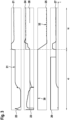
- Fig. 3 shows exemplary parameter curves that can be achieved when performing steps a) and b) of a method proposed here.
- a PWM signal 21 pulse width modulated signal
- the course of the volume flow 22 detected by the volume flow sensor 5 the course of the setting position 25 of the circuit regulating valve 16 and the differential pressure 26 are shown.
- a first differential pressure 27 can be determined, which is required to operate the first heating circuit 10 in the design state.
- the following substeps a1), b1), c1), d1, and e1) shown in blocks 130, 140, 150, 160, and 170 can be performed for this purpose.
- step a1) the circuit regulating valve 16 can be completely closed, whereby the entire volume flow 22 pumped by the first circulation pump 8 flows from the heat generator circuit 13 into the first heating circuit 10. This can be seen in the course of the setting position 25 of the circuit regulating valve 16 by setting the closing position 30.
- a predetermined first target volume flow 23 for the first heating circuit 10 can be adjusted using the first circulation pump 8 and the volume flow sensor 5 in the heat generator circuit 13.
- the first target volume flow 23 can be the target volume flow of the first heating circuit 10 in the design state, which was determined according to a heating load calculation.
- the first target volume flow 23 is established as recognizable by the profile of the volume flow 22.
- the corresponding PWM signal 21 of the first circulation pump 8 can be detected as the first pump operating parameter 31 in block 150 according to step c1) and stored in a memory.
- a pump differential pressure 12 between the inlet and outlet of the first circulation pump 8 can be determined based on the first pump operating parameter 31 determined in step c1) and a predetermined pump characteristic.
- the pump characteristic is a characteristic curve specific to the specific pump, which establishes a relationship between the volume flow 22, the PWM signal 21, and the delivery head or the pump differential pressure generated by the pump.
- a first differential pressure 27 (i.e., a value of the pump differential pressure 12) can be determined based on the pump differential pressure 12 (delivery head) determined in step d1) (block 160) and a pressure loss determined by the predetermined pressure loss characteristic of the heat generator circuit 13.
- the first differential pressure 27 can be determined, which is composed of the pump differential pressure and the pressure loss of the heat generator circuit 13.
- a second predetermined target volume flow 24 in the heat generator circuit 13 can be adjusted by means of the volume flow sensor 5, and the first differential pressure 27 determined in step a) can be adjusted by means of the circuit regulating valve 16.
- Two control circuits can be used for this purpose.
- step b) can be executed according to one embodiment by performing the substeps a2) and b2) shown in blocks 180 and 190.
- Substeps a2) and b2) can be executed in particular in parallel or simultaneously.
- a predetermined second target volume flow 24 in the heat generator circuit 13 can be adjusted by means of the volume flow sensor 5 of the heat generator circuit 13 and the first circulation pump 8.
- Fig. 3 is a corresponding increase in the PWM signal 21 of the first circulation pump 8 and an increase in the volume flow 22.
- the first differential pressure 27 determined in step a) can be adjusted using the balancing valve 16 as the actuator.
- the setting position 25 of the balancing valve 16 is changed so that it opens until a first setting position 32 has been adjusted, at which the course of the differential pressure 26 is adjusted to the first differential pressure 27.
- FIG. 3 A design condition of 500 liters per hour was realized in the first heating circuit 10 and potentially in the second heating circuit 11.
- the heating system 1 can now be operated energy-efficiently with the volume flows 22 provided for in the design condition.
- Fig. 3 also shows a tested volume flow 28 of the first heating circuit, which corresponds to the first target volume flow 23 set in step a1), thus confirming the success of the process.
- the tested volume flow 28 was determined externally as part of a laboratory test.
- the second heating circuit 11 can set a flow temperature by means of the three-way mixing valve 17 and a volume flow by means of the second circulation pump 19.
- the first setting position 32 on the circuit regulating valve 16 can be fixed and the power of the first circulation pump 8 can be reduced.
Landscapes
- Engineering & Computer Science (AREA)
- Physics & Mathematics (AREA)
- Thermal Sciences (AREA)
- Chemical & Material Sciences (AREA)
- Combustion & Propulsion (AREA)
- Mechanical Engineering (AREA)
- General Engineering & Computer Science (AREA)
- Steam Or Hot-Water Central Heating Systems (AREA)
Applications Claiming Priority (1)
| Application Number | Priority Date | Filing Date | Title |
|---|---|---|---|
| DE102023130537.9A DE102023130537A1 (de) | 2023-11-06 | 2023-11-06 | Verfahren zum Betreiben einer Heizungsanlage, Heizungsanlage und Computerprogramm |
Publications (1)
| Publication Number | Publication Date |
|---|---|
| EP4549822A1 true EP4549822A1 (fr) | 2025-05-07 |
Family
ID=93379163
Family Applications (1)
| Application Number | Title | Priority Date | Filing Date |
|---|---|---|---|
| EP24210458.6A Pending EP4549822A1 (fr) | 2023-11-06 | 2024-11-04 | Procédé de fonctionnement d'une installation de chauffage, installation de chauffage et programme informatique |
Country Status (2)
| Country | Link |
|---|---|
| EP (1) | EP4549822A1 (fr) |
| DE (1) | DE102023130537A1 (fr) |
Citations (4)
| Publication number | Priority date | Publication date | Assignee | Title |
|---|---|---|---|---|
| SE420864B (sv) * | 1976-09-16 | 1981-11-02 | Carlson R H D | Anordning vid central vermeanleggning |
| EP1163478B1 (fr) * | 1999-03-20 | 2004-05-26 | KSB Aktiengesellschaft | Systeme de transport fluidique |
| DE102014226450A1 (de) * | 2014-12-18 | 2016-06-23 | Robert Bosch Gmbh | Verfahren zum Durchführen eines automatisierten hydraulischen Abgleich einer Heinzungsanlage |
| EP3217101A1 (fr) * | 2016-03-08 | 2017-09-13 | PAW GmbH & Co. KG | Procédé de désolidarisation hydraulique de plusieurs circuits de fluides commutés en parallèle |
-
2023
- 2023-11-06 DE DE102023130537.9A patent/DE102023130537A1/de active Pending
-
2024
- 2024-11-04 EP EP24210458.6A patent/EP4549822A1/fr active Pending
Patent Citations (4)
| Publication number | Priority date | Publication date | Assignee | Title |
|---|---|---|---|---|
| SE420864B (sv) * | 1976-09-16 | 1981-11-02 | Carlson R H D | Anordning vid central vermeanleggning |
| EP1163478B1 (fr) * | 1999-03-20 | 2004-05-26 | KSB Aktiengesellschaft | Systeme de transport fluidique |
| DE102014226450A1 (de) * | 2014-12-18 | 2016-06-23 | Robert Bosch Gmbh | Verfahren zum Durchführen eines automatisierten hydraulischen Abgleich einer Heinzungsanlage |
| EP3217101A1 (fr) * | 2016-03-08 | 2017-09-13 | PAW GmbH & Co. KG | Procédé de désolidarisation hydraulique de plusieurs circuits de fluides commutés en parallèle |
Also Published As
| Publication number | Publication date |
|---|---|
| DE102023130537A1 (de) | 2025-05-08 |
Similar Documents
| Publication | Publication Date | Title |
|---|---|---|
| EP3665542B1 (fr) | Dispositif de réglage autorégulé pour une vanne de régulation de fluide, système de thermorégulation et un système de distribution comprenant celui-ci, ainsi que procédé associé | |
| EP2960587B1 (fr) | Procédé de limitation du débit d'alimentation dans un système de transmission de chaleur | |
| EP1936290B1 (fr) | Procédé et dispositif destinés à la détection de l'état hydraulique d'une installation de chauffage | |
| EP3593055B1 (fr) | Procédé pour faire fonctionner une installation de chauffage | |
| EP2863134B1 (fr) | Procédé d'adaptation d'une courbe de chauffe | |
| EP3101352B1 (fr) | Procede de fonctionnement d'une installation de chauffage et dispositif de regulation comprenant un capteur de difference de pression | |
| DE102014016791B4 (de) | Verfahren zur hydraulischen Regelung mehrerer Heizkreisläufe am Verteilerbalken | |
| DE102014102275B4 (de) | Verfahren zur Regelung einer Heizungs- und/oder Klimaanlage und Heizungs- und/oder Klimaanlage hierzu | |
| WO2015067439A1 (fr) | Procédé de diagnostic pour diagnostiquer le bon fonctionnement d'un système de chauffage et/ou de refroidissement | |
| EP3473939B1 (fr) | Procédé de fonctionnement d'une installation de chauffage et installation de chauffage | |
| EP3800403B1 (fr) | Procédé de fonctionnement d'un dispositif de chauffage, dispositif de chauffage | |
| DE3620929A1 (de) | Verfahren und einrichtung zur regelung mindestens einer heizung | |
| EP4549822A1 (fr) | Procédé de fonctionnement d'une installation de chauffage, installation de chauffage et programme informatique | |
| EP3168540A1 (fr) | Procédé d'exécution d'un équilibrage hydraulique automatisé, soupape et installation de chauffage associées | |
| DE102020211169A1 (de) | Verfahren zum Steuern eines Heizungssystems | |
| EP0192228A2 (fr) | Procédé de régulation de température de locaux avec des dispositifs de chauffage et/ou de refroidissement | |
| DE102015008758A1 (de) | Verfahren zur Einstellung von energiesparenden Heizungssystemen | |
| EP4209718A1 (fr) | Appareil de chauffage, procédé de fonctionnement d'un appareil de chauffage, produit-programme informatique, appareil de réglage et de commande et utilisation d'une soupape de moteur pas à pas | |
| EP3997389B1 (fr) | Procédé de commande d'un ensemble composé d'une pompe de chauffage et d'une vanne mélangeuse à trois voies | |
| AT526014A1 (de) | Verfahren zum Kühlen oder Heizen von Räumen | |
| DE102022101313A1 (de) | Verfahren zur Konfiguration eines Klimasystems, Computerprogramm, Regel- und Steuerge-rät, Klimagerät und Verwendung von Daten | |
| EP4015918A1 (fr) | Procédé et dispositif de commande d'un circuit primaire d'une installation de chauffage | |
| DE102023202099A1 (de) | Verfahren zum Betrieb eines Heizungssystems | |
| EP4343213B1 (fr) | Procédé de réalisation d'un équilibrage hydraulique d'une installation de chauffage | |
| DE19737250C2 (de) | Steuerungsvorrichtung für Heizanlagen |
Legal Events
| Date | Code | Title | Description |
|---|---|---|---|
| PUAI | Public reference made under article 153(3) epc to a published international application that has entered the european phase |
Free format text: ORIGINAL CODE: 0009012 |
|
| STAA | Information on the status of an ep patent application or granted ep patent |
Free format text: STATUS: THE APPLICATION HAS BEEN PUBLISHED |
|
| AK | Designated contracting states |
Kind code of ref document: A1 Designated state(s): AL AT BE BG CH CY CZ DE DK EE ES FI FR GB GR HR HU IE IS IT LI LT LU LV MC ME MK MT NL NO PL PT RO RS SE SI SK SM TR |
|
| STAA | Information on the status of an ep patent application or granted ep patent |
Free format text: STATUS: REQUEST FOR EXAMINATION WAS MADE |
|
| 17P | Request for examination filed |
Effective date: 20251105 |