EP4550450A1 - Silicium-kohlenstoff-verbundmaterial und herstellungsverfahren dafür sowie sekundärbatterie damit - Google Patents
Silicium-kohlenstoff-verbundmaterial und herstellungsverfahren dafür sowie sekundärbatterie damit Download PDFInfo
- Publication number
- EP4550450A1 EP4550450A1 EP22956160.0A EP22956160A EP4550450A1 EP 4550450 A1 EP4550450 A1 EP 4550450A1 EP 22956160 A EP22956160 A EP 22956160A EP 4550450 A1 EP4550450 A1 EP 4550450A1
- Authority
- EP
- European Patent Office
- Prior art keywords
- silicon
- optionally
- composite material
- carbon composite
- carbon
- Prior art date
- Legal status (The legal status is an assumption and is not a legal conclusion. Google has not performed a legal analysis and makes no representation as to the accuracy of the status listed.)
- Pending
Links
Images



Classifications
-
- C—CHEMISTRY; METALLURGY
- C01—INORGANIC CHEMISTRY
- C01B—NON-METALLIC ELEMENTS; COMPOUNDS THEREOF; METALLOIDS OR COMPOUNDS THEREOF NOT COVERED BY SUBCLASS C01C
- C01B32/00—Carbon; Compounds thereof
- C01B32/05—Preparation or purification of carbon not covered by groups C01B32/15, C01B32/20, C01B32/25, C01B32/30
-
- C—CHEMISTRY; METALLURGY
- C01—INORGANIC CHEMISTRY
- C01B—NON-METALLIC ELEMENTS; COMPOUNDS THEREOF; METALLOIDS OR COMPOUNDS THEREOF NOT COVERED BY SUBCLASS C01C
- C01B33/00—Silicon; Compounds thereof
- C01B33/02—Silicon
-
- C—CHEMISTRY; METALLURGY
- C23—COATING METALLIC MATERIAL; COATING MATERIAL WITH METALLIC MATERIAL; CHEMICAL SURFACE TREATMENT; DIFFUSION TREATMENT OF METALLIC MATERIAL; COATING BY VACUUM EVAPORATION, BY SPUTTERING, BY ION IMPLANTATION OR BY CHEMICAL VAPOUR DEPOSITION, IN GENERAL; INHIBITING CORROSION OF METALLIC MATERIAL OR INCRUSTATION IN GENERAL
- C23C—COATING METALLIC MATERIAL; COATING MATERIAL WITH METALLIC MATERIAL; SURFACE TREATMENT OF METALLIC MATERIAL BY DIFFUSION INTO THE SURFACE, BY CHEMICAL CONVERSION OR SUBSTITUTION; COATING BY VACUUM EVAPORATION, BY SPUTTERING, BY ION IMPLANTATION OR BY CHEMICAL VAPOUR DEPOSITION, IN GENERAL
- C23C16/00—Chemical coating by decomposition of gaseous compounds, without leaving reaction products of surface material in the coating, i.e. chemical vapour deposition [CVD] processes
- C23C16/04—Coating on selected surface areas, e.g. using masks
- C23C16/045—Coating cavities or hollow spaces, e.g. interior of tubes; Infiltration of porous substrates
-
- C—CHEMISTRY; METALLURGY
- C23—COATING METALLIC MATERIAL; COATING MATERIAL WITH METALLIC MATERIAL; CHEMICAL SURFACE TREATMENT; DIFFUSION TREATMENT OF METALLIC MATERIAL; COATING BY VACUUM EVAPORATION, BY SPUTTERING, BY ION IMPLANTATION OR BY CHEMICAL VAPOUR DEPOSITION, IN GENERAL; INHIBITING CORROSION OF METALLIC MATERIAL OR INCRUSTATION IN GENERAL
- C23C—COATING METALLIC MATERIAL; COATING MATERIAL WITH METALLIC MATERIAL; SURFACE TREATMENT OF METALLIC MATERIAL BY DIFFUSION INTO THE SURFACE, BY CHEMICAL CONVERSION OR SUBSTITUTION; COATING BY VACUUM EVAPORATION, BY SPUTTERING, BY ION IMPLANTATION OR BY CHEMICAL VAPOUR DEPOSITION, IN GENERAL
- C23C16/00—Chemical coating by decomposition of gaseous compounds, without leaving reaction products of surface material in the coating, i.e. chemical vapour deposition [CVD] processes
- C23C16/22—Chemical coating by decomposition of gaseous compounds, without leaving reaction products of surface material in the coating, i.e. chemical vapour deposition [CVD] processes characterised by the deposition of inorganic material, other than metallic material
- C23C16/24—Deposition of silicon only
-
- H—ELECTRICITY
- H01—ELECTRIC ELEMENTS
- H01M—PROCESSES OR MEANS, e.g. BATTERIES, FOR THE DIRECT CONVERSION OF CHEMICAL ENERGY INTO ELECTRICAL ENERGY
- H01M10/00—Secondary cells; Manufacture thereof
- H01M10/05—Accumulators with non-aqueous electrolyte
- H01M10/052—Li-accumulators
-
- H—ELECTRICITY
- H01—ELECTRIC ELEMENTS
- H01M—PROCESSES OR MEANS, e.g. BATTERIES, FOR THE DIRECT CONVERSION OF CHEMICAL ENERGY INTO ELECTRICAL ENERGY
- H01M10/00—Secondary cells; Manufacture thereof
- H01M10/05—Accumulators with non-aqueous electrolyte
- H01M10/052—Li-accumulators
- H01M10/0525—Rocking-chair batteries, i.e. batteries with lithium insertion or intercalation in both electrodes; Lithium-ion batteries
-
- H—ELECTRICITY
- H01—ELECTRIC ELEMENTS
- H01M—PROCESSES OR MEANS, e.g. BATTERIES, FOR THE DIRECT CONVERSION OF CHEMICAL ENERGY INTO ELECTRICAL ENERGY
- H01M4/00—Electrodes
- H01M4/02—Electrodes composed of, or comprising, active material
- H01M4/04—Processes of manufacture in general
- H01M4/0402—Methods of deposition of the material
- H01M4/0421—Methods of deposition of the material involving vapour deposition
- H01M4/0428—Chemical vapour deposition
-
- H—ELECTRICITY
- H01—ELECTRIC ELEMENTS
- H01M—PROCESSES OR MEANS, e.g. BATTERIES, FOR THE DIRECT CONVERSION OF CHEMICAL ENERGY INTO ELECTRICAL ENERGY
- H01M4/00—Electrodes
- H01M4/02—Electrodes composed of, or comprising, active material
- H01M4/04—Processes of manufacture in general
- H01M4/0471—Processes of manufacture in general involving thermal treatment, e.g. firing, sintering, backing particulate active material, thermal decomposition, pyrolysis
-
- H—ELECTRICITY
- H01—ELECTRIC ELEMENTS
- H01M—PROCESSES OR MEANS, e.g. BATTERIES, FOR THE DIRECT CONVERSION OF CHEMICAL ENERGY INTO ELECTRICAL ENERGY
- H01M4/00—Electrodes
- H01M4/02—Electrodes composed of, or comprising, active material
- H01M4/13—Electrodes for accumulators with non-aqueous electrolyte, e.g. for lithium-accumulators; Processes of manufacture thereof
- H01M4/133—Electrodes based on carbonaceous material, e.g. graphite-intercalation compounds or CFx
-
- H—ELECTRICITY
- H01—ELECTRIC ELEMENTS
- H01M—PROCESSES OR MEANS, e.g. BATTERIES, FOR THE DIRECT CONVERSION OF CHEMICAL ENERGY INTO ELECTRICAL ENERGY
- H01M4/00—Electrodes
- H01M4/02—Electrodes composed of, or comprising, active material
- H01M4/13—Electrodes for accumulators with non-aqueous electrolyte, e.g. for lithium-accumulators; Processes of manufacture thereof
- H01M4/134—Electrodes based on metals, Si or alloys
-
- H—ELECTRICITY
- H01—ELECTRIC ELEMENTS
- H01M—PROCESSES OR MEANS, e.g. BATTERIES, FOR THE DIRECT CONVERSION OF CHEMICAL ENERGY INTO ELECTRICAL ENERGY
- H01M4/00—Electrodes
- H01M4/02—Electrodes composed of, or comprising, active material
- H01M4/13—Electrodes for accumulators with non-aqueous electrolyte, e.g. for lithium-accumulators; Processes of manufacture thereof
- H01M4/139—Processes of manufacture
- H01M4/1395—Processes of manufacture of electrodes based on metals, Si or alloys
-
- H—ELECTRICITY
- H01—ELECTRIC ELEMENTS
- H01M—PROCESSES OR MEANS, e.g. BATTERIES, FOR THE DIRECT CONVERSION OF CHEMICAL ENERGY INTO ELECTRICAL ENERGY
- H01M4/00—Electrodes
- H01M4/02—Electrodes composed of, or comprising, active material
- H01M4/36—Selection of substances as active materials, active masses, active liquids
-
- H—ELECTRICITY
- H01—ELECTRIC ELEMENTS
- H01M—PROCESSES OR MEANS, e.g. BATTERIES, FOR THE DIRECT CONVERSION OF CHEMICAL ENERGY INTO ELECTRICAL ENERGY
- H01M4/00—Electrodes
- H01M4/02—Electrodes composed of, or comprising, active material
- H01M4/36—Selection of substances as active materials, active masses, active liquids
- H01M4/362—Composites
-
- H—ELECTRICITY
- H01—ELECTRIC ELEMENTS
- H01M—PROCESSES OR MEANS, e.g. BATTERIES, FOR THE DIRECT CONVERSION OF CHEMICAL ENERGY INTO ELECTRICAL ENERGY
- H01M4/00—Electrodes
- H01M4/02—Electrodes composed of, or comprising, active material
- H01M4/36—Selection of substances as active materials, active masses, active liquids
- H01M4/362—Composites
- H01M4/364—Composites as mixtures
-
- H—ELECTRICITY
- H01—ELECTRIC ELEMENTS
- H01M—PROCESSES OR MEANS, e.g. BATTERIES, FOR THE DIRECT CONVERSION OF CHEMICAL ENERGY INTO ELECTRICAL ENERGY
- H01M4/00—Electrodes
- H01M4/02—Electrodes composed of, or comprising, active material
- H01M4/36—Selection of substances as active materials, active masses, active liquids
- H01M4/38—Selection of substances as active materials, active masses, active liquids of elements or alloys
- H01M4/386—Silicon or alloys based on silicon
-
- H—ELECTRICITY
- H01—ELECTRIC ELEMENTS
- H01M—PROCESSES OR MEANS, e.g. BATTERIES, FOR THE DIRECT CONVERSION OF CHEMICAL ENERGY INTO ELECTRICAL ENERGY
- H01M4/00—Electrodes
- H01M4/02—Electrodes composed of, or comprising, active material
- H01M4/36—Selection of substances as active materials, active masses, active liquids
- H01M4/58—Selection of substances as active materials, active masses, active liquids of inorganic compounds other than oxides or hydroxides, e.g. sulfides, selenides, tellurides, halogenides or LiCoFy; of polyanionic structures, e.g. phosphates, silicates or borates
- H01M4/583—Carbonaceous material, e.g. graphite-intercalation compounds or CFx
-
- H—ELECTRICITY
- H01—ELECTRIC ELEMENTS
- H01M—PROCESSES OR MEANS, e.g. BATTERIES, FOR THE DIRECT CONVERSION OF CHEMICAL ENERGY INTO ELECTRICAL ENERGY
- H01M4/00—Electrodes
- H01M4/02—Electrodes composed of, or comprising, active material
- H01M4/36—Selection of substances as active materials, active masses, active liquids
- H01M4/58—Selection of substances as active materials, active masses, active liquids of inorganic compounds other than oxides or hydroxides, e.g. sulfides, selenides, tellurides, halogenides or LiCoFy; of polyanionic structures, e.g. phosphates, silicates or borates
- H01M4/583—Carbonaceous material, e.g. graphite-intercalation compounds or CFx
- H01M4/587—Carbonaceous material, e.g. graphite-intercalation compounds or CFx for inserting or intercalating light metals
-
- H—ELECTRICITY
- H01—ELECTRIC ELEMENTS
- H01M—PROCESSES OR MEANS, e.g. BATTERIES, FOR THE DIRECT CONVERSION OF CHEMICAL ENERGY INTO ELECTRICAL ENERGY
- H01M4/00—Electrodes
- H01M4/02—Electrodes composed of, or comprising, active material
- H01M4/62—Selection of inactive substances as ingredients for active masses, e.g. binders, fillers
- H01M4/624—Electric conductive fillers
- H01M4/625—Carbon or graphite
-
- C—CHEMISTRY; METALLURGY
- C01—INORGANIC CHEMISTRY
- C01P—INDEXING SCHEME RELATING TO STRUCTURAL AND PHYSICAL ASPECTS OF SOLID INORGANIC COMPOUNDS
- C01P2002/00—Crystal-structural characteristics
- C01P2002/70—Crystal-structural characteristics defined by measured X-ray, neutron or electron diffraction data
- C01P2002/74—Crystal-structural characteristics defined by measured X-ray, neutron or electron diffraction data by peak-intensities or a ratio thereof only
-
- C—CHEMISTRY; METALLURGY
- C01—INORGANIC CHEMISTRY
- C01P—INDEXING SCHEME RELATING TO STRUCTURAL AND PHYSICAL ASPECTS OF SOLID INORGANIC COMPOUNDS
- C01P2004/00—Particle morphology
- C01P2004/51—Particles with a specific particle size distribution
-
- C—CHEMISTRY; METALLURGY
- C01—INORGANIC CHEMISTRY
- C01P—INDEXING SCHEME RELATING TO STRUCTURAL AND PHYSICAL ASPECTS OF SOLID INORGANIC COMPOUNDS
- C01P2006/00—Physical properties of inorganic compounds
- C01P2006/12—Surface area
-
- C—CHEMISTRY; METALLURGY
- C01—INORGANIC CHEMISTRY
- C01P—INDEXING SCHEME RELATING TO STRUCTURAL AND PHYSICAL ASPECTS OF SOLID INORGANIC COMPOUNDS
- C01P2006/00—Physical properties of inorganic compounds
- C01P2006/14—Pore volume
-
- C—CHEMISTRY; METALLURGY
- C01—INORGANIC CHEMISTRY
- C01P—INDEXING SCHEME RELATING TO STRUCTURAL AND PHYSICAL ASPECTS OF SOLID INORGANIC COMPOUNDS
- C01P2006/00—Physical properties of inorganic compounds
- C01P2006/40—Electric properties
-
- H—ELECTRICITY
- H01—ELECTRIC ELEMENTS
- H01M—PROCESSES OR MEANS, e.g. BATTERIES, FOR THE DIRECT CONVERSION OF CHEMICAL ENERGY INTO ELECTRICAL ENERGY
- H01M4/00—Electrodes
- H01M4/02—Electrodes composed of, or comprising, active material
- H01M2004/021—Physical characteristics, e.g. porosity, surface area
-
- H—ELECTRICITY
- H01—ELECTRIC ELEMENTS
- H01M—PROCESSES OR MEANS, e.g. BATTERIES, FOR THE DIRECT CONVERSION OF CHEMICAL ENERGY INTO ELECTRICAL ENERGY
- H01M4/00—Electrodes
- H01M4/02—Electrodes composed of, or comprising, active material
- H01M2004/026—Electrodes composed of, or comprising, active material characterised by the polarity
- H01M2004/027—Negative electrodes
-
- Y—GENERAL TAGGING OF NEW TECHNOLOGICAL DEVELOPMENTS; GENERAL TAGGING OF CROSS-SECTIONAL TECHNOLOGIES SPANNING OVER SEVERAL SECTIONS OF THE IPC; TECHNICAL SUBJECTS COVERED BY FORMER USPC CROSS-REFERENCE ART COLLECTIONS [XRACs] AND DIGESTS
- Y02—TECHNOLOGIES OR APPLICATIONS FOR MITIGATION OR ADAPTATION AGAINST CLIMATE CHANGE
- Y02E—REDUCTION OF GREENHOUSE GAS [GHG] EMISSIONS, RELATED TO ENERGY GENERATION, TRANSMISSION OR DISTRIBUTION
- Y02E60/00—Enabling technologies; Technologies with a potential or indirect contribution to GHG emissions mitigation
- Y02E60/10—Energy storage using batteries
Definitions
- the present application relates to the technical field of batteries, and in particular to a silicon-carbon composite material and a preparation method thereof, and a secondary battery including the silicon-carbon composite material.
- Graphite is usually used as a negative electrode material in the second batteries, but the theoretical capacity of the graphite is low (372mA ⁇ h/g), which cannot meet the demand for the secondary batteries with higher volume capacity and energy density.
- a silicon-base material has become a more ideal negative electrode material of the secondary batteries due to its extremely high theoretical capacity (4200 mAh/g) and low lithium insertion potential.
- the extremely low electrical conductivity and large volume expansion of the silicon material limit the application of the silicon material. Therefore, how to improve the electrochemical performance of the secondary batteries which take the silicon-based material as the negative electrode material has become an urgent technical problem.
- an objective of the present application is to provide a silicon-carbon composite material.
- the composite material has high electrical conductivity and structural stability, so that the composite material can improve the energy density of a secondary battery and also can make the secondary battery have a good cycle life.
- the present application provides a silicon-carbon composite material.
- the silicon-carbon composite material includes a porous carbon matrix and silicon-based particles.
- the porous carbon matrix internally includes a plurality of pore channels with a width of 5 nm-50 nm.
- the silicon-based particles are distributed in the pore channels, and the porous carbon matrix meets: 1.0 ⁇ 10 -7 ⁇ V total /S total ⁇ 10 ⁇ 10 -7 , where S total is the total surface area occupied by the pore channels with the width of 5 nm-50 nm, and the measurement unit is: ⁇ 10 4 cm 2 /g; and V total is the total pore volume occupied by the pore channels with the width of 5 nm-50 nm, and the measurement unit is: cm 3 /g.
- the silicon-carbon composite material provided by the present application has a porous carbon matrix.
- the porous carbon matrix has a plurality of long and narrow pore channels, so that the porous carbon matrix forms a crosslinked three-dimensional net structure, and the silicon-based particles are distributed in the mutually crosslinked pore channels.
- the three-dimensional net structure of the porous carbon matrix can accommodate and limit the expansion of the silicon-based particles and improve the damage to the structure of the composite material caused by the expansion of the silicon-based particles in the battery cycle process, so as to improve the cycle stability of the composite material in the battery; and on the other hand, the specific pore distribution and structure of the porous carbon matrix are favorable for silicon to occupy pores in a carbon skeleton and be dispersed inside the carbon material, and efficient electron transmission can be realized through the crosslinked carbon skeleton with high electrical conductivity, so that the silicon-carbon composite material has high specific capacity and high electrical conductivity, and is conducive to reducing the polarization of the battery when being applied to the battery.
- 10 ⁇ S total ⁇ 50, optionally, 1 ⁇ S total ⁇ 30, and the unit is: ⁇ 10 4 cm 2 /g.
- the porous carbon matrix has long and narrow pore channels with a width of 5 nm-50 nm, the porous carbon matrix meeting the above condition forms a three-dimensional crosslinked net structure, and at least two pore channels communicating with each other are present in the structure, so that the porous carbon matrix has the three-dimensional net structure and also has large specific surface area, and has enough position and volume for the silicon-based particles to be distributed thereon.
- the pore channel structure in the porous carbon matrix has large volume and can accommodate and limit the expansion of the silicon-based particles in the battery cycle process, thereby maintaining the structural stability of the silicon-carbon material in the battery cycle process.
- the powder resistivity of the porous carbon matrix under the pressure of 4 MPa is 1 ⁇ /cm-300 ⁇ /cm, optionally, 1 ⁇ /cm-100 ⁇ /cm.
- the silicon-carbon composite material provided by the embodiments of the present application has a porous carbon matrix with extremely low powder resistivity, and a carbon skeleton with high electrical conductivity is constructed through the porous carbon matrix, so that the silicon-carbon composite material obtained by compounding the carbon skeleton and the silicon-based particles also has high electrical conductivity.
- the grain size of the silicon-based particles is less than or equal to 20 nm, preferably, 2 nm-10 nm.
- the volume particle size distribution of the porous carbon matrix is: D v50 ⁇ 10 ⁇ m, optionally, 5 ⁇ D v50 ⁇ 10 ⁇ m; and/or the volume particle size distribution of the porous carbon matrix is: D v90 ⁇ 20 ⁇ m, optionally, 10 ⁇ D v90 ⁇ 15 ⁇ m.
- the content of the silicon-based particles in the silicon-carbon composite material is 25%-65%, optionally, 35%-45%.
- the problems of excessively low silicon content and low specific capacity of the silicon-carbon composite material can be effectively avoided, or the problems of excessively high silicon content and damage to the excellent electric conductivity of the carbon skeleton caused by excessive silicon-based particles can be avoided. Therefore, it is conducive to increase the specific capacity of the silicon-carbon composite material and improve the cycle stability of the silicon-carbon material in the battery.
- the powder resistivity R of the silicon-carbon composite material under the pressure of 12 MPa is less than or equal to 300 ⁇ /cm, optionally, 1.1 ⁇ /cm-200 ⁇ /cm; and/or the powder resistivity R of the silicon-carbon composite material under the pressure of 16 MPa is less than or equal to 200 ⁇ /cm, optionally, 1 ⁇ /cm-100 ⁇ /cm.
- the silicon-based particles are uniformly distributed inside the matrix, and the silicon-carbon composite material has low powder resistivity, in other words, good electrical conductivity, so that the silicon-carbon composite material has high specific capacity in the battery, and also has good structural stability and cycle stability.
- the silicon-carbon composite material meets one or more of the following (1) to (6): (1) the volume particle size distribution of the silicon-carbon composite material is Dv10 ⁇ 5 ⁇ m, optionally, 3 ⁇ Dv10 ⁇ 5 ⁇ m; (2) the volume particle size distribution of the silicon-carbon composite material is Dv50 ⁇ 10 ⁇ m, optionally, 5 ⁇ Dv10 ⁇ 8 ⁇ m; (3) the volume particle size distribution of the silicon-carbon composite material is 10 ⁇ Dv90 ⁇ 20 ⁇ m, optionally, 10 ⁇ Dv90 ⁇ 15 ⁇ m; (4) the volume particle size distribution of the silicon-carbon composite material is (Dv90-Dv10)/Dv50 ⁇ 1.8, optionally, 1.4 ⁇ (Dv90-Dv10)/Dv50 ⁇ 1.6; (5) the compaction density of the silicon-carbon composite material under the pressure of 2 MPa is 1 g/cm 3 -1.5 g/cm 3 , optionally, 1.1 g/cm 3 -1.3 g/cm 3 ; and (6) the specific surface area of
- the peak value of an X-ray diffraction (XRD) peak of the carbon-based composite material between the diffraction angle 28° and 29° is denoted as P1
- the peak value of an XRD peak of the silicon-based particles between the diffraction angle 42° and 45° is denoted as P2
- 2 ⁇ P1/P2 ⁇ 4 optionally, 600 ⁇ P1 ⁇ 800, and optionally, 200 ⁇ P2 ⁇ 400.
- a preparation method of a silicon-carbon composite material includes: mixing a base material and a pore-forming agent in a solvent to obtain a first mixture; treating the first mixture at a high temperature to obtain a porous carbon matrix; and depositing a silane gas in the porous carbon matrix through chemical vapor deposition to obtain the silicon-carbon composite material.
- the base material includes at least one of sugar and resin; optionally, the sugar includes at least one of glucose, sucrose, fructose, starch, amylopectin, amylose, lignin, dextrin and maltodextrin; and optionally, the resin includes at least one of linear phenolic resin, soluble phenolic resin, epoxy resin and polyurethane.
- the pore-forming agent includes at least one of sodium chloride, potassium chloride, zinc chloride, sodium carbonate and potassium carbonate.
- a mass ratio of the base material to the pore-forming agent is 1:5-10:1, optionally, 2:1-5:1.
- the use amount of the pore-forming agent is determined according to the amount of the base material, so that the situation that sufficient gas cannot be generated to form a pore channel structure of 2 nm-10 nm due to the insufficient use amount of the pore-forming agent can be avoided, or the situation that local reaction is violent to rapidly generate gas due to the excessive use amount of the pore-forming agent to cause large pores can be avoided. Therefore, it can be ensured that the prepared porous carbon matrix has a three-dimensional net structure formed by mutually crosslinked pore channels of 5 nm-50 nm by controlling the mass ratio of the base material to the pore-forming agent within a suitable range.
- the solvent includes water or alcohol, where the alcohol includes at least one of methanol, ethanol, ethylene glycol, polyethylene glycol, glycerol, isopropanol or polyalcohol.
- the mass ratio of the base material to the solvent is 1:100-10:1, optionally, 1:2-10:1.
- the use amount of the solvent is determined according to the amount of the base material, the situation that after the pore-forming agent generates gas, the gas cannot be dispersed timely due to excessively few solvents and excessively high viscosity of the first mixture to cause the pore size larger or longer can be avoided, or the situation that after the pore-forming agent generates gas, the gas is discharged rapidly due to excessive use amount of the solvent and excessively low viscosity of the first mixture to cause the pore-forming failure can be avoided. Therefore, the quality of the pore channels in the prepared porous carbon matrix can be further ensured by controlling the mass ratio of the base material to the solvent within a suitable range.
- the mixing a base material and a pore-forming agent in a solvent includes: mixing the base material and the pore-forming agent in the solvent through stirring, where optionally, the stirring speed is 100 rpm/min-1500 rpm/min, further optionally, 200 rpm/min-1000 rpm/min.
- the treating the first mixture at a high temperature to obtain a porous carbon matrix includes: treating the first mixture at a first temperature to obtain a second mixture, where the second mixture is a solid mixture; treating the second mixture at a second temperature to obtain a carbon precursor; and treating the carbon precursor at a third temperature to obtain the porous carbon matrix.
- the first mixture is treated at the first temperature, and in this process, the excess solvent is volatilized and the base material is preliminarily solidified into the second mixture; then, the second mixture is treated at the second temperature, and in this process, the first mixture is further solidified to form the carbon precursor; and subsequently, the carbon precursor is treated at the third temperature, and in this process, the pore-forming agent in the carbon precursor and the residual solvent are pyrolyzed to generate gas at high temperature so as to form pores in the base material. Therefore, through the multi-temperature and multi-step heating processes, the first mixture can be converted into the porous carbon matrix with the mutually crosslinked pore channel structures inside. Through the multi-temperature and multi-step heating, the distribution uniformity of the pore-forming agent in the carbon precursor can be effectively improved, so that the pore channels in the finally prepared porous carbon matrix are uniformly distributed in the material.
- the first temperature, the second temperature and the third temperature meet one or more of the following (I) to (III): (I) the first temperature is 40°C-80°C, optionally, 40°C -60°C; (II) the second temperature is 100°C-200°C, optionally, 150°C-180°C; and (III) the third temperature is 600°C-1200°C, optionally, 800°C-1000°C.
- the situation that the first temperature is excessively high, a large number of aggregated micropores appear locally and the finally obtained pore channels are excessively long or oversized pore channels appear can be avoided, or the situation that the first temperature is excessively low, which is not conducive to the solidification of the first mixture and affects the subsequent processing can be avoided.
- the preparation method includes: crushing the second mixture before treating the second mixture at the second temperature.
- the preparation method further includes: crushing the carbon precursor before treating the carbon precursor at the third temperature, where optionally, after the carbon precursor is crushed, the particle size of the carbon precursor is 1 ⁇ m-1000 ⁇ m, further optionally, 5 ⁇ m-100 ⁇ m.
- the treating the carbon precursor at a third temperature includes: treating the carbon precursor in an inert gas at the third temperature, where optionally, the inert gas includes at least one of nitrogen, argon and helium.
- the preparation method further includes: performing impurity removal and/or demagnetization on the porous carbon matrix before depositing the silicon-based particles in the porous carbon matrix.
- the atmosphere of the chemical vapor deposition is a mixed gas of a silane gas and hydrogen, where optionally, the volume of the silane gas accounts for 10%-50% of the volume of the mixed gas.
- the flow of depositing the silane gas through the chemical vapor deposition is 0.5 L/min-1 L/min; and/or the temperature of the chemical vapor deposition is 500 °C -800 °C.
- the condition of the chemical vapor deposition is controlled to meet the above condition, so that the silane gas enters the porous carbon matrix slowly and is decomposed and deposited uniformly in the pore channels of the porous carbon matrix, thereby preventing the silicon-based particles from being deposited on the surface of the material and reducing the resistivity of the silicon-carbon composite material.
- a secondary battery includes: a negative electrode plate.
- the negative electrode plate includes the silicon-carbon composite material in any embodiment of the first aspect, or includes the silicon-carbon composite material prepared by the method in any embodiment of the second aspect.
- an electrical apparatus includes the secondary battery in any embodiment of the third aspect.
- Range disclosed in the present application is limited in the form of a lower limit and an upper limit, a given range is limited by selecting one lower limit and one upper limit, and the selected lower limit and upper limit define the boundary of a specific range.
- the range limited in this way may include or not include an end value, and may be combined arbitrarily, that is, any lower limit may be combined with any upper limit to form a range.
- ranges of 60-120 and 80-110 are listed for specific parameters, it is understood that the ranges of 60-110 and 80-120 are also expected.
- the minimum range values of 1 and 2 and the maximum range values of 3, 4 and 5 are listed, the following ranges may be all expected: 1-3, 1-4, 1-5, 2-3, 2-4 and 2-5.
- the numeral range “a-b” means the abbreviated representation of any combination of real numbers between a and b, where a and b are both real numbers.
- the numerical range "0-5" means that all real numbers between "0-5" have been listed in the specification, and "0-5" is only the abbreviated representation of these numerical combinations.
- a certain parameter is expressed as an integer greater than or equal to 2, the parameter is disclosed equivalently, for example, an integer of 2, 3, 4, 5, 6, 7, 8, 9, 10, 11 and 12.
- a plurality of means two or more; orientation o positional relationships indicated by the terms “upper”, “lower”, “left”, “right”, “inner”, “outer”, and the like are only for the convenience of description of the present application and simplification of description rather than indicating or implying that the referenced device or element must have a particular orientation, be constructed and operated in a particular orientation, and thus are not to be construed as limiting the present application.
- the terms “first”, “second”, “third”, and the like are used for descriptive purposes only and are not to be construed as indicating or implying relative importance.
- “Vertical” is not strictly vertical, but within the allowable range of error.
- Parallel is not strictly parallel, but within the allowable range of error.
- the term "or” in the present application is inclusive.
- the phrase “A or B” means “A, B or both A and B”. More specifically, any of the following conditions meets the condition "A or B”: A is true (or exists) and B is false (or does not exist); A is false (or does not exist) and B is true (or exists); or both A and B are true (or exist).
- a secondary battery includes a positive electrode plate, a negative electrode plate, an electrolyte and a separator.
- active ions are intercalated and de-intercalated between the positive electrode plate and the negative electrode plate back and forth.
- the electrolyte plays a role in conducting ions between the positive electrode plate and the negative electrode plate.
- the separator is arranged between the positive electrode plate and the negative electrode plate, which can mainly prevent the short circuit between a positive electrode and a negative electrode and allow ions to pass through.
- the secondary battery may include a lithium-ion battery, a sodium-ion battery and a magnesium-ion battery.
- the present application takes the lithium-ion battery as an example.
- the lithium-ion battery is a typical secondary battery.
- the lithium-ion battery is also called a rocking chair battery because the lithium-ion battery relies on the chemical reaction of lithium ion de-intercalation and intercalation between the positive and negative electrodes for charging and discharging.
- the lithium ions In the charging process of the lithium-ion battery, the lithium ions are de-intercalated from the positive electrode, moved and intercalated into the negative electrode; and in the discharging process, the lithium ions are de-intercalated from the negative electrode, moved and intercalated into the positive electrode.
- the secondary battery has been greatly developed and widely applied to many fields of electrical tools, electronic products, electrical vehicles, aerospace and the like. Higher requirements are put forward for the volume capacity, energy density and cycle performance of the secondary battery.
- graphite has become one of the most commonly used negative electrode materials due to its extensive sources, rich reserves and stable electrochemical properties.
- the theoretical capacity of the graphite is low (372mA ⁇ h/g), which cannot meet the demand for the secondary batteries with higher volume capacity and energy density.
- a silicon material also has extensive sources and rich reserves, has extremely high theoretical capacity (4200 mAh/g) and low lithium intercalation potential, also has high chemical stability in an electrolyte solution and is not easy to generate side reaction with the electrolyte, thereby gradually becoming a more ideal negative electrode material of the secondary battery.
- the surface of the negative electrode material is continuously damaged due to the expansion of the silicon material, and the SEI film is continuously damaged accordingly and then is regenerated, thereby resulting in unnecessary consumption of the lithium ions and affecting the capacity of the secondary battery.
- the silicon material belongs to a semiconductor material and has low electrical conductivity and large interface impedance, thereby greatly hindering the conduction of electrons on the surface and the interior of the silicon material and affecting the rate performance of the secondary battery.
- the present application provides a silicon-carbon composite material.
- the silicon-carbon composite material includes a porous carbon matrix and silicon-based particles distributed in the porous carbon matrix.
- the silicon-based particles are distributed in mutually crosslinked pore channels of the porous carbon matrix, so that the silicon-carbon composite material has extremely high volume capacity and energy density.
- the porous carbon matrix has a three-dimensional net structure and high electrical conductivity, and the volume expansion of the silicon-based particles can be accommodated and limited in the space inside the mutually crosslinked pore channels, so that the silicon-carbon composite material has high electrical conductivity, rate performance and cycle performance.
- lithium intercalation and intercalation processes mentioned in the present application refer to a process in which lithium ions are intercalated in a positive electrode material and a negative electrode material due to an electrochemical reaction; and the "removal”, “lithium de-intercalation” and “de-intercalation” mentioned in the present application refer to a process in which the lithium ions are de-intercalated from the positive electrode material and the negative electrode material due to the electrochemical reaction.
- the present application provides a silicon-carbon composite material.
- the silicon-carbon composite material includes a porous carbon matrix and silicon-based particles.
- the porous carbon matrix internally includes a plurality of pore channels with a width of 5 nm-50 nm.
- the silicon-based particles are distributed in the pore channels, and the porous carbon matrix meets: 1.0 ⁇ V total /S total ⁇ 10 and the unit is: 10 -7 cm, where S total is the total surface area occupied by the pore channels with the width of 5 nm-50 nm, and the measurement unit is: ⁇ 10 4 cm 2 /g; and V total is the total pore volume occupied by the pore channels with the width of 5 nm-50 nm, and the measurement unit is: cm 3 /g.
- V total /S total may be 1, 2, 3, 4, 5, 6, 7, 8, 9 and 10, or the value thereof is within a range obtained by combining any two of the above values.
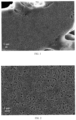
- FIG. 1 and FIG. 2 are scanning electron microscope (SEM) diagrams of a porous carbon matrix according to an embodiment of the present application.
- the porous carbon matrix has rich pore channel structures and mutually crosslinked three-dimensional network-shaped carbon skeletons.
- V total /S total represents an average pore length of the pore channels in the porous carbon matrix.
- the porous carbon matrix forms the carbon skeletons with the three-dimensional network structures due to the plurality of pore channel structures therein.
- the carbon skeleton serves as an electronic conductor, and a conducting model of the carbon skeleton may be compared with a parallel circuit.
- the parallel circuit Ohm's law meets a formula (I):
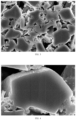
- FIG. 3 and FIG. 4 are scanning electron microscope (SEM) diagrams of a silicon-carbon composite material according to an embodiment of the present application.
- the silicon-carbon composite material provided by the present application is mainly composed of a porous carbon matrix and silicon-based particles distributed in pore channel structures of the porous carbon matrix.
- the porous carbon matrix meeting the above condition is different from the general carbon matrix and has a plurality of pore channel structures therein. At least two of the plurality of pore channel structures communicate with each other, so that the porous carbon matrix forms a three-dimensional net structure.
- the porous carbon matrix has high electrical conductivity, and the electron transmission efficiency of a silicon-carbon interface can be effectively improved after the silicon-based particles are compounded on the porous carbon matrix; and on the other hand, the rich crosslinked pore channel structures can effectively accommodate and limit the volume expansion of the silicon-based particles in the battery cycle process, so that the structural stability of the silicon-carbon composite material can be effectively improved, and structural damage caused by the volume expansion of the silicon-based particles can be reduced.
- the silicon-based particles are distributed in the pore channel structures uniformly. Therefore, when the silicon-carbon composite material is applied to the negative electrode of the battery, the volume capacity and energy density of the battery can be effectively increased, and high cycle performance and rate performance can be achieved.
- V total /S total may be 2, 2.5, 3, 3.5, 4, 4.5 and 5, or the value thereof is within a range obtained by combining any two of the above values.
- the electrical conductivity of the porous carbon matrix can be further improved by further reducing the length range of the pore channels in the porous carbon matrix, thereby improving the electrical conductivity of the silicon-carbon composite material and helping to improve the cycle stability and rate performance of the battery.
- 1 ⁇ S total ⁇ 50 optionally, 1 ⁇ S total ⁇ 30, and the unit is: ⁇ 10 4 cm 2 /g.
- S total may be 1, 3, 4, 5, 6, 7, 8, 9, 10, 12, 14, 16, 18, 20, 22, 24, 26, 28, 30, 32, 34, 36, 38, 40, 42, 44, 46, 48 and 50, or the value thereof is within a range obtained by combining any two of the above values.
- V total may be 0.002, 0.004, 0.007, 0.008, 0.009, 0.10, 0.11, 0.12, 0.13, 0.14, 0.15, 0.16, 0.17, 0.18, 0.18, 0.20, 0.21, 0.22, 0.23, 0.24 and 0.25, or the value combination thereof is within a range obtained by combining any two of the above values.
- the porous carbon matrix meeting the above condition has a three-dimensional crosslinked net structure and large specific surface area, so that the surface of the porous carbon matrix has sufficient space for the distribution of the silicon-based particles. Therefore, the silicon-carbon composite material obtained by compounding the porous carbon matrix and the silicon-based particles has extremely high volume capacity and energy density. Meanwhile, the pore channels in the porous carbon matrix meeting the above condition has sufficient volume and can accommodate and limit the expansion of the silicon-based particles compounded in the pore channels in the battery cycle process, thereby maintaining the structural stability of the silicon-carbon composite material in the battery cycle process and effectively improving the cycle performance of the battery.
- the grain size of the silicon-based particles is less than or equal to 20 nm, preferably, 2 nm-10 nm.
- the volume particle size distribution of the porous carbon matrix is: D v50 ⁇ 10 ⁇ m, optionally, 5 ⁇ D v50 ⁇ 10 ⁇ m; and/or the volume particle size distribution of the porous carbon matrix is: D v90 ⁇ 20 ⁇ m, optionally, 10 ⁇ D v90 ⁇ 15 ⁇ m.
- the porous carbon matrix is crushed before being compounded with the silicon-based particles to form the silicon-carbon composite material, so that the granular porous carbon matrix.
- the micro-sized porous carbon matrix and the silicon-based particles are compounded, which is beneficial for the silicon-based particles to enter and be deposited in the pore channels of the porous carbon matrix instead of being deposited on the surfaces of the carbon skeletons. If the silicon-based particles are only deposited on the surface, the porous carbon matrix with high electrical conductivity will be wrapped by the silicon-based particles with low electrical conductivity, thereby destroying the high electrical conductivity of the whole silicon-carbon composite material. Therefore, the porous carbon matrix is crushed before compounding, which is beneficial for the silicon-based particles to be uniformly deposited in the pore channels and helps to improve the electrical conductivity of the silicon-carbon composite material.
- the content of the silicon-based particles in the silicon-carbon composite material is 25%-65%, optionally, 35%-45%.
- the content of the silicon-based particles in the silicon-carbon composite material may be 25%, 26%, 27%, 28%, 29%, 30%, 31%, 32%, 33%, 34%, 35%, 36%, 37%, 38%, 39%, 40%, 41%, 42%, 43%, 44% and 45%, or the value combination thereof is within a range obtained by combining any two of the above values.
- the content of the silicon-based particles in the silicon-carbon composite material is controlled within an appropriate range.
- sufficient silicon-based particles can be compounded in the silicon-carbon composite material, and the volume capacity and energy density of the silicon-carbon composite material can be increased as much as possible; and on the other hand, due to the low electrical conductivity of the silicon-based particles, the content of the silicon-based particles is controlled within an appropriate range, which can avoid the influence on the electrical conductivity of the silicon-carbon composite material caused by the excessive silicon-based particles in the silicon-carbon composite material. Therefore, the silicon-carbon composite material can have high specific capacity and high electrical conductivity by controlling the content of the silicon-based particles in the silicon-carbon composite material.
- the powder resistivity of the porous carbon matrix under the pressure of 4 MPa is 1 ⁇ /cm-300 ⁇ /cm, optionally, 1 ⁇ /cm-100 ⁇ /cm.
- the powder resistivity of the porous carbon matrix under the pressure of 4 MPa may be 1 ⁇ /cm, 5 ⁇ /cm, 10 ⁇ /cm, 15 ⁇ /cm, 20 ⁇ /cm, 25 ⁇ /cm, 30 ⁇ /cm, 35 ⁇ /cm, 40 ⁇ /cm, 45 ⁇ /cm, 50 ⁇ /cm, 55 ⁇ /cm, 60 ⁇ /cm, 65 ⁇ /cm, 70 ⁇ /cm, 75 ⁇ /cm, 80 ⁇ /cm, 85 ⁇ /cm, 90 ⁇ /cm, 95 ⁇ /cm, 100 ⁇ /cm, 150 ⁇ /cm, 200 ⁇ /cm, 250 ⁇ /cm and 300 ⁇ /cm, or the value combination thereof is within a range obtained by combining any two of the above values.
- a porous carbon bracket has low resistivity due to the crosslinked net structure.
- the silicon-carbon composite material can have low resistivity and show high electrical conductivity when serving as an electrode active material, thereby improving the cycle stability of the battery.
- the powder resistivity R of the silicon-carbon composite material under the pressure of 12 MPa is less than or equal to 300 ⁇ /cm, optionally, 1 ⁇ /cm-200 ⁇ /cm; and/or the powder resistivity R of the silicon-carbon composite material under the pressure of 16 MPa is less than or equal to 200 ⁇ /cm, optionally, 1 ⁇ /cm-100 ⁇ /cm.
- the powder resistivity of the silicon-carbon composite material under the pressure of 12 MPa may be 1 ⁇ /cm, 5 ⁇ /cm, 10 ⁇ /cm, 15 ⁇ /cm, 20 ⁇ /cm, 25 ⁇ /cm, 30 ⁇ /cm, 35 ⁇ /cm, 40 ⁇ /cm, 45 ⁇ /cm, 50 ⁇ /cm, 55 ⁇ /cm, 60 ⁇ /cm, 65 ⁇ /cm, 70 ⁇ /cm, 75 ⁇ /cm, 80 ⁇ /cm, 85 ⁇ /cm, 90 ⁇ /cm, 95 ⁇ /cm, 100 ⁇ /cm, 150 ⁇ /cm, 200 ⁇ /cm, 250 ⁇ /cm and 300 ⁇ /cm, or the value combination thereof is within a range obtained by combining any two of the above values.
- the powder resistivity of the silicon-carbon composite material under the pressure of 16 MPa may be 1 ⁇ /cm, 5 ⁇ /cm, 10 ⁇ /cm, 15 ⁇ /cm, 20 ⁇ /cm, 25 ⁇ /cm, 30 ⁇ /cm, 35 ⁇ /cm, 40 ⁇ /cm, 45 ⁇ /cm, 50 ⁇ /cm, 55 ⁇ /cm, 60 ⁇ /cm, 65 ⁇ /cm, 70 ⁇ /cm, 75 ⁇ /cm, 80 ⁇ /cm, 85 ⁇ /cm, 90 ⁇ /cm, 95 ⁇ /cm, 100 ⁇ /cm, 150 ⁇ /cm and 200 ⁇ /cm, or the value combination thereof is within a range obtained by combining any two of the above values.
- the silicon-carbon composite material meets one or more of the following (1) to (6):
- the silicon-carbon composite material obtained by the silicon-carbon composite material obtained by compounding the porous carbon matrix and the silicon-based particles has at least one of the following properties (1) to (6).
- the compaction density of the silicon-carbon composite material under the pressure of 2 MPa is 1 g/cm 3 1.1 g/cm 3 , 1.2 g/cm 3 , 1.3 g/cm 3 , 1.4 g/cm 3 and 1.5 g/cm 3 , or the value thereof is within a range obtained by combining any two of the above values.
- the SSA of the silicon-carbon composite material may be 2 m 2 /g, 2.5 m 2 /g, 3 m 2 /g, 3.5 m 2 /g, 4 m 2 /g, 4.5 m 2 /g, 5 m 2 /g, 5.5 m 2 /g, 6 m 2 /g, 6.5 m 2 /g, 7 m 2 /g, 7.5 m 2 /g, 8 m 2 /g, 8.5 m 2 /g, 9 m 2 /g, 9.5 m 2 /g and 10 m 2 /g.
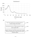
- the peak value of an X-ray diffraction (XRD) peak of the silicon-carbon composite material between the diffraction angle 28° and 29° is denoted as P1
- the peak value of an XRD peak of the silicon-based particles between the diffraction angle 42° and 45° is denoted as P2
- 2 ⁇ P1/P2 ⁇ 4 optionally, 600 ⁇ P1 ⁇ 800, and optionally, 200 ⁇ P2 ⁇ 400.
- FIG. 5 is an XRD peak diagram of a silicon-carbon composite material according to an embodiment of the present application.
- the silicon-carbon composite material has an obvious diffraction peak within the range of the diffraction angle of 28°-29° and 42°-45°, where the diffraction angle of 28°-29° is a feature peak of the carbon material, and the diffraction angle of 42°-45° is a feature peak of the silicon material.
- FIG. 6 is a schematic flowchart of a preparation method of a silicon-carbon composite material according to an embodiment of the present application.
- the preparation method 600 of the silicon-carbon composite material includes:
- the silicon-based particles include at least one of silicon oxide, nano-silicon and alloy silicon.
- the silicon oxide includes but is not limited to: silicon monoxide, silicon dioxide and the like.
- the alloy silicon includes but is not limited to silicone alloy, ferrosilicon alloy, silicon-aluminum alloy and the like.
- a base material includes at least one of resin, sugar or other polymers.
- the resin includes but is not limited to linear phenolic resin, soluble phenolic resin, epoxy resin, polyurethane and the like.
- the sugar includes but is not limited to glucose, sucrose, fructose, starch, amylopectin, amylose, lignin, dextrin and maltodextrin.
- other polymers include but are not limited to acrylate, a styrene polymer, carbamate, rubber, nylon and the like.
- the pore-forming agent includes at least one of sodium chloride, potassium chloride, zinc chloride, sodium carbonate, potassium carbonate and zinc carbonate.
- the solvent includes but is not limited to water or alcohol.
- the solvent may further be a mixture of water and alcohol, that is, an alcohol solution.
- the alcohol includes but is not limited to methanol, ethanol, ethylene glycol, polyethylene glycol, glycerol, isopropanol or polyalcohol.
- a mass ratio of the base material to the pore-forming agent is 1:5-10:1, optionally, 2:1-5:1.
- the mass ratio of the base material to the pore-forming agent is 1:5, 1:4, 1:3, 1:2, 1:1, 2:1, 3:1, 4:1, 5:1, 6:1, 7:1, 8:1, 9:1 and 10:1, or the value thereof is within a range obtained by any two of the above values.
- the use amount of the pore-forming agent can be determined according to the use amount of the base material, so that the mass ratio of the base material to the pore-forming agent is within an appropriate range, the situation that sufficient gas cannot be generated to form a narrow and long pore channel due to the too small use amount can be avoided, and the situation that local reaction is violent to rapidly generate a large amount of gas due to the excessive use amount of the pore-forming agent to cause large pores can be avoided.
- the shape and size of the pore channel in the porous carbon matrix can be effectively regulated and controlled by controlling the mass ratio of the base material to the pore-forming agent, so that the pore channel structure with an appropriate size and narrow and a long shape can be prepared.
- a mass ratio of the base material to the pore-forming agent is 1:100-10:1, optionally, 1:2-10:1.
- the mass ratio of the base material to the pore-forming agent is 1:100, 1:90, 1:80, 1:70, 1:60, 1:50, 1:40, 1:30, 1:20, 1:10, 1:9, 1:8, 1:7, 1:6, 1:5, 1:4, 1:3, 1:2, 1:1, 2:1, 3:1, 4:1, 5:1, 5:1, 7:1, 8:1, 9:1 and 10:1, or the value thereof is within a range obtained by any two of the above values.
- the use amount of the solvent is determined according to the use amount of the base material, so that the mass ratio of the base material to the solvent is within an appropriate range, the situation that after the pore-forming agent generates gas, the gas cannot be dispersed timely due to excessively few solvents and excessively high viscosity of the first mixture to cause the pore size larger or longer can be avoided, and the situation that after the pore-forming agent generates gas, the gas is discharged rapidly from the first mixture due to the excessive solvent and excessively low viscosity of the first mixture to cause the pore-forming failure can be avoided.
- the mix a base material and a pore-forming agent in a solvent includes: mix the base material and the pore-forming agent in the solvent through stirring.
- the solvent may be placed in a container with a stirring apparatus such as a stirrer and spiral stirring, and the stirring apparatus stirs the solvent at a certain speed.
- the base material and the pore-forming agent are added in the solvent, and are stirred for a certain time to obtain the first mixture with a uniform volume phase.
- the process of adding the base material in the solvent may be: adding the base material and then adding the pore-forming agent, or adding the pore-forming agent and then adding the base material, or adding the base material and the pore-forming agent at the same time, which is not limited by the embodiments of the present application.
- the stirring speed is 100 rpm/min-1500 rpm/min, optionally, 200 rpm/min-1000 rpm/min.
- the stirring speed may be 100 rpm/min, 200 rpm/min, 300 rpm/min, 400 rpm/min, 500 rpm/min, 600 rpm/min, 700 rpm/min, 800 rpm/min, 900 rpm/min, 1000 rpm/min, 1100 rpm/min, 1200 rpm/min, 1300 rpm/min, 1400 rpm/min and 1500 rpm/min, or the value thereof is within a range obtained by any two of the above values.
- the base material, the pore-forming agent and the solvent can be mixed rapidly and uniformly, and waste caused by splattering of the liquid mixture due to excessively high rotating speed can be avoided.
- FIG. 7 is another schematic flowchart of a preparation method 600 of a silicon-carbon composite material according to an embodiment of the present application.
- the treating the first mixture at a high temperature to obtain a porous carbon matrix includes:
- the carbon precursor is treated at T3, the pore-forming agent is decomposed at T3 to generate a gas so as to form pores in the carbon precursor, and the carbon precursor is subjected to reaction at T3 to generate a carbon skeleton with a porous structure, that is, the porous carbon matrix.
- the distribution uniformity of the pore-forming agent in the carbon precursor can be effectively regulated and controlled through the multi-temperature and multi-step process, so that the first mixture is converted into the porous carbon matrix with uniform crosslinked pore channel structures inside.
- T1 is 40°C-80°C, optionally, T1 is 40°C -60°C.
- T1 may be 40°C, 45°C, 50°C, 55°C, 60°C, 65°C, 70°C, 75°C and 80°C, or the value thereof is within a range obtained by any two of the above values.
- T1 is the preliminary solidification temperature of the first mixture.
- the T1 is controlled within an appropriate range, so that the situation that T1 is excessively high, the pore-forming agent is excessively dispersed, the pore channels cannot be mutually crosslinked in the subsequent pore-forming process and a large number of micro-pores appear can be avoided, and the situation that excessively low T1 is not conducive to the solidification and formation of the first mixture and the subsequent preparation process is affected can be avoided.
- T2 is 100°C-200°C, optionally, T2 is 130°C-180°C.
- T2 may be 130°C, 140°C, 150°C, 160°C, 170°C, 180°C, 190°C and 200°C, or the value thereof is within a range obtained by any two of the above values.
- T3 is 600°C-1200°C, optionally, T3 is 800°C -1000°C.
- T3 may be 600°C, 700°C, 800°C, 900°C, 1000°C, 1100°C and 1200°C, or the value thereof is within a range obtained by any two of the above values.
- the preparation method 600 further includes: crush the second mixture.
- the second mixture may be treated into powdery solid through the process steps of coarse crushing, fine crushing and grinding, that is, the second mixture is crushed.
- the second mixture is treated at T2 after being crushed, thereby avoiding the situation that the solvent in the block-shaped second mixture cannot be volatilized or cannot be further solidified.
- the preparation method 600 further includes: crush the carbon precursor.
- the particle size of the carbon precursor is 1 ⁇ m-1000 ⁇ m, optionally, 5 ⁇ m-100 ⁇ m.
- the obtained carbon precursor may be further crushed, the carbon precursor is treated into micro-sized particles, and then the carbon precursor is treated at T3, thereby increasing the reaction degree of a carbonization reaction, and avoiding the situation that the large granular carbon precursor is carbonized only on the surface and not inside. Therefore, the quality of the prepared porous carbon matrix is improved.
- the particle size of the crushed carbon precursor may be 1 ⁇ m, 2 ⁇ m, 3 ⁇ m, 4 ⁇ m, 5 ⁇ m, 6 ⁇ m, 7 ⁇ m, 8 ⁇ m, 9 ⁇ m, 10 ⁇ m, 50 ⁇ m, 100 ⁇ m, 150 ⁇ m, 200 ⁇ m, 300 ⁇ m, 400 ⁇ m, 500 ⁇ m, 600 ⁇ m, 700 ⁇ m, 800 ⁇ m, 900 ⁇ m and 1000 ⁇ m, or the value thereof is within a range obtained by any two of the above values.
- the treat the carbon precursor at T3 includes: treat the carbon precursor at T3 in an inert gas.
- the inert gas includes at least one of nitrogen (N 2 ), argon (Ar) and helium (He).
- the carbon precursor is treated at a high temperature in the inert gas, so that the carbon precursor can be protected from reacting with oxygen, and the carbon precursor is subjected to carbonization reaction, thereby obtaining the porous carbon matrix with rich pore channel structures.
- the preparation method 600 further includes: perform impurity removal and/or demagnetization on the porous carbon matrix.
- the carbon precursor is further screened through the technical processes of impurity removal and demagnetization to obtain micro-sized carbon precursor particles which are more in line with requirements, thereby improving the quality of the prepared porous carbon matrix.
- the porous carbon matrix is usually placed in a silicon-containing gas at a high temperature, so that the silicon in the silicon-containing gas can be deposited in the pore channels of the porous carbon to generate silicon-based particles.
- the silicon-containing gas includes at least one of a silane gas, silicon dichloride, silicon trichloride and silicon tetrachloride.
- the silicon-containing gas may further include hydrogen, the inert gas and other gases.
- the silicon-containing gas includes a plurality of gases
- the silicon-containing gas may include 01%-1% by volume of silicon dichloride and the balance of nitrogen, or the silicon-containing gas may include 1%-10% by volume of silicon dichloride and the balance of nitrogen, or the silicon-containing gas may include 10%-50% by volume of silicon dichloride and the balance of nitrogen, or the silicon-containing gas may include more than 50% by volume of silicon dichloride and the balance of nitrogen.
- the CVD atmosphere is a mixed gas of the silane gas and the hydrogen.
- the silane gas accounts for 10%-50% of the volume of the mixed gas.
- the temperature of the CVD is 500°C-800°C.
- the temperature of the CVD may be 500°C, 550°C, 600°C, 650°C, 700°C, 750°C and 800°C, or the value thereof is within a range obtained by any two of the above values.
- the porous carbon matrix and the silicon-based particles are compounded through CVD to obtain the silicon-carbon composite material.
- the CVD is controlled to meet the above condition, so that the silicon in the silicon-containing gas can be uniformly deposited in the pore channels of the porous carbon matrix, and the silicon-carbon composite material with extremely high electrical conductivity can be obtained.
- the porous carbon matrix and the silicon-based particles may be compounded through plasma enhanced chemical vapor deposition (PECVD).
- PECVD plasma enhanced chemical vapor deposition
- the base material and the pore-forming agent are firstly dispersed uniformly in the solvent, and in the subsequent high-temperature treatment process, the solvent and the pore-forming agent act jointly for pore formation to obtain narrow and long pore channels that are crosslinked mutually.
- the carbon skeleton with the special pore channel structures has a three-dimensional net structure, so that the porous carbon matrix has low resistivity.
- the flow of the silane gas is controlled within an appropriate range, so that the silane gas enters the pore channels of the porous carbon matrix slowly and completely and are decomposed and deposited in the pore channels uniformly, thereby preventing the silicon-based particles from being deposited only on the surface of the material. Therefore, the silicon-carbon interface completely extends into the silicon-carbon composite material, and compared with the ordinary silicon-carbon material, the electrical conductivity of the material is significantly improved.
- the resistivity of the silicon-carbon composite material prepared by the method 600 is usually 100 ⁇ /cm-10000 ⁇ /cm.
- the negative electrode plate usually includes a negative electrode current collector and a negative electrode film arranged on at least one surface of the negative electrode current collector.
- the negative electrode film includes a negative electrode active material.
- the negative electrode current collector has two opposite surfaces in a thickness direction of the negative electrode current collector; and the negative electrode film is arranged on any one or two of the two opposite surfaces of the negative electrode current collector.
- the negative electrode active material is the silicon-carbon composite material provided by any embodiment of the present application.
- the negative electrode active material may further include a mixture formed by mixing at least one of other negative electrode active materials for the battery known in the art and the silicon-carbon composite material provided by any embodiment of the present application.
- other negative electrode active materials may include at least one of the following materials: artificial graphite, natural graphite, soft carbon, hard carbon, elemental silicon, silicon oxide, a silicon-carbon composite material, a silicon-nitrogen complex, silicon alloy, a tin-based material and lithium titanate.
- the tin-based material may be selected from at least one of elemental tin, tin oxide and tin alloy.
- the negative electrode current collector may adopt a metal foil or a composite current collector.
- a metal foil a copper foil may be adopted.
- the composite current collector may include a macro-molecular material base layer, and a metal layer formed on at least one surface of the macro-molecular material base layer.
- the composite current collector may be formed by forming a metal material (copper, copper alloy, nickel, nickel alloy, titanium, titanium alloy, silver and silver alloy) on the macro-molecular material base material (such as polypropylene (PP), polyethylene terephthalate (PET), polybutylene terephthalate (PBT), polystyrene (PS) and polyethylene (PE)).
- PP polypropylene
- PET polyethylene terephthalate
- PBT polybutylene terephthalate
- PS polystyrene
- PE polyethylene
- the negative electrode film includes a binding agent.
- the binding agent may be selected from at least one of butadiene styrene rubber (SBR), polyacrylic acid (PAA), polyacrylic acid sodium (PAAS), polyacrylamide (PAM), polyvinly alcohol (PVA), sodium alginate (SA), polymethylacrylic acid (PMAA) and carboxymethyl chitosan (CMCS).
- the negative electrode film includes a conductive agent.
- the conductive agent may be selected from at least one of superconductive carbon, acetylene black, carbon black, Ketjen black, a carbon dot, a carbon nanotube, graphene and carbon nanofiber.
- the negative electrode film further includes other aids, for example, a thickening agent (such as carboxymethylcellulose sodium (CMC-Na)).
- a thickening agent such as carboxymethylcellulose sodium (CMC-Na)
- the negative electrode plate may be prepared by the following ways: disperse the components for preparing the negative electrode plate, for example, the negative electrode active material, the conductive agent, the binding agent and any other components, into the solvent (such as deionized water) to form a negative electrode slurry; and coat the negative electrode current collector with the negative electrode slurry and then obtain the negative electrode plate through the processes of drying and cold pressing.
- the solvent such as deionized water
- the positive electrode current collector has two opposite surfaces in a thickness direction of the positive electrode current collector; and the positive electrode film is arranged on any one or two of the two opposite surfaces of the positive electrode current collector.
- the example of the lithium transition metal oxide may include but not limited to at least one of lithium cobalt oxide (such as LiCoO 2 ), lithium nickel oxide (such as LiNiO 2 ), lithium manganese oxide (such as LiMnO 2 and LiMn 2 O 4 ), lithium nickel cobalt oxide, lithium manganese cobalt oxide, lithium manganese nickel oxide, lithium nickel cobalt manganese oxide (such as LiNi 1/3 Co 1/3 Mn 1/3 O 2 (that may be referred to as NCM333 for short), LiNi 0.5 Co 0.2 Mn 0.3 O 2 (that may be referred to as NCM523 for short), LiNi 0.5 Co 0.25 Mn 0.25 O 2 (that may be referred to as NCM211 for short), LiNi 0.6 Co 0.2 Mn 0.2 O 2 (that may be referred to as NCM622 for short) and LiNi 0.8 Co 0.1 Mn 0.1 O 2 (that may be referred to as NCM811 for short) ), lithium nickel cobalt aluminum oxide (such
- the example of the lithium-containing phosphate with the olivine structure may include but not limited to at least one of lithium iron phosphate (such as LiFePO 4 (that may be referred to as LFP for short)), a composite material of lithium iron phosphate and carbon, lithium manganese phosphate (such as LiMnPO 4 ), a composite material of lithium manganese phosphate and carbon, lithium ferromanganese phosphate and a composite material of lithium ferromanganese phosphate and carbon.
- lithium iron phosphate such as LiFePO 4 (that may be referred to as LFP for short)
- LiMnPO 4 lithium manganese phosphate
- the positive electrode film may optionally include a binding agent.
- the binding agent may include at least one of polyvinylidene fluoride (PVDF), polytetrafluoroethylene (PTFE), a vinylidene fluoride-tetrafluoroethylene-propylene terpolymer, a vinylidene fluoride-hexafluoropropylene-tetrafluoroethylene terpolymer, a tetrafluoroethylene-hexafluoropropylene copolymer and fluorinated acrylate resin.
- PVDF polyvinylidene fluoride
- PTFE polytetrafluoroethylene
- PTFE polytetrafluoroethylene
- the positive electrode film further includes a conductive agent.
- the conductive agent may include at least one of superconductive carbon, acetylene black, carbon black, Ketjen black, a carbon dot, a carbon nanotube, graphene and carbon nanofiber.
- the positive electrode material further optionally includes a binding agent.
- the binding agent may include at least one of polyvinylidene fluoride (PVDF), polytetrafluoroethylene (PTFE), a vinylidene fluoride-tetrafluoroethylene-propylene terpolymer, a vinylidene fluoride-hexafluoropropylene-tetrafluoroethylene terpolymer, a tetrafluoroethylene-hexafluoropropylene copolymer and fluorinated acrylate resin.
- PVDF polyvinylidene fluoride
- PTFE polytetrafluoroethylene
- PTFE polytetrafluoroethylene
- the positive electrode plate may be prepared by the following ways: disperse the components for preparing the positive electrode plate, for example, the positive electrode active material, the conductive agent, the binding agent and any other components, into the solvent (such as N-methylpyrrolidone) to form a positive electrode slurry; and coat the positive electrode current collector with the positive electrode slurry and then obtain the negative electrode plate through the processes of drying and cold pressing.
- the solvent such as N-methylpyrrolidone
- the electrolyte plays a role in conducting ions between the positive electrode plate and the negative electrode plate.
- the type of the electrolyte may not be specifically limited by the present application, and may be selected according to requirements.
- the electrolyte may be liquid, gel or all-solid.
- the electrolyte adopts an electrolyte solution.
- the electrolyte solution includes an electrolyte salt and a solvent.
- the electrolyte salt may be selected from at least one of lithium hexafluorophosphate, lithium tetrafluoroborate, lithium perchlorate, lithium hexafluoroarsenate, lithium difluorosulfonimide, lithium trifluoromethanesulfonate, lithium triflate, lithium difluorophosphate, lithium bis(oxalate)borate, lithium difluoroborate, lithium difluorodioxalate phosphate and lithium tetrafluorooxalate phosphate.
- the solvent may be selected from at least one of ethylene carbonate, propyl carbonate, ethyl methyl carbonate, diethyl carbonate, dimethyl carbonate, dipropyl carbonate, methyl propyl carbonate, ethyl propyl carbonate, butylene carbonate, fluoroethylene carbonate, methyl formate, methyl acetate, ethyl acetate, propyl acetate, methyl propionate, ethyl propionate, propyl propionate, methyl butyrate, ethyl butyrate, 1, 4-butyrolactone, sulfolane, dimethyl sulfone, methyl ethyl sulfone and diethyl sulfone.
- the electrolyte solution further includes an additive.
- the additive may include a negative electrode film-forming additive and a positive electrode film-forming additive, and may further include an additive capable of improving some performance of the battery, for example, an additive capable of improving the overcharge performance of the battery and an additive capable of improving the high-temperature or low-temperature performance of the battery.
- the secondary battery further includes a separator.
- the type of the separator is not specially limited by the present application, for example, any well-known porous structure isolating film with high chemical stability and mechanical stability may be adopted.
- a material of the isolating film may be selected from at least one of glass fiber, non-woven fabric, polyethylene, polypropylene and polyvinylidene fluoride.
- the isolating film may be a single-layer film, or may be a multi-layer composite film, which is not particularly limited herein.
- a material of each layer may be the same or different, which is not particularly limited herein.
- the positive electrode plate, the negative electrode plate and the isolating film may be made into an electrode assembly through a winding process or a lamination process.
- the secondary battery may include an outer package.
- the outer package may be configured to package the electrode assembly and the electrolyte.
- the outer package of the secondary battery may be a hard shell, for example, a hard plastic shell, an aluminum shell and a steel shell.
- the outer package of the secondary battery may also be a soft package, for example, a bag-type soft package.
- a material of the soft package may be plastic, as plastic, for example, polypropylene, polybutylene terephthalate and polybutylene succinate.
- the shape of the secondary battery is not particularly limited by the present application, and may be a cylinder, a square or any other shapes.
- FIG. 8 is a secondary battery 800 with a square structure as an example.
- the outer package of the secondary battery 800 may include a shell 801 and a cover plate 802.
- the shell 801 may include a bottom plate and a side plate connected to the bottom plate. An accommodating cavity is surrounded by the bottom and the side plate.
- the shell 801 has an opening communicating with the accommodating cavity, and the cover plate 802 can cover the opening to close the accommodating cavity.
- the positive electrode plate, the negative electrode plate and the isolating film form an electrode assembly 803 through a winding process or a lamination process, and the electrode assembly 803 is packaged into the accommodating cavity and infiltrated into the electrode assembly 803.
- the number of the electrode assemblies 803 included in the secondary battery 800 may be one or more, which may be selected by those skilled in the art according to actual requirements.
- the secondary battery 800 may be assembled into a battery module.
- the number of the secondary batteries 800 included in the battery module may be one or more. The specific number may be selected by those skilled in the art according to the application scenario and capacity of the battery module.
- FIG. 9 is a schematic structural diagram of a battery module 900.
- a plurality of secondary batteries 800 may be arranged sequentially in a length direction of the battery module 900, and of course, may be arranged according to any other manners. Further, the plurality of secondary batteries 800 may be fixed through a fastener.
- the battery module 900 may further include an outer shell with an accommodating space, and the plurality of secondary batteries 800 are accommodated in the accommodating space.
- the battery module 900 may be assembled into a battery pack.
- the number of the battery modules 900 included in the battery pack may be one or more. The specific number may be selected by those skilled in the art according to the application scenario and capacity of the battery pack.
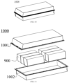
- FIG. 10 and FIG. 11 are schematic diagrams of a battery pack 1000.
- the battery pack 1000 may include a battery box and a plurality of battery modules 900 arranged in the battery box.
- the battery box includes an upper box body 1001 and a lower box body 1002.
- the upper box body 1001 can cover the lower box body 1002 and form a closed space for accommodating the battery modules 900.
- the plurality of battery modules 900 may be arranged in the battery box according to any manner.
- FIG. 12 is a schematic diagram of an electrical apparatus 1200 according to the present application.
- the electrical apparatus 1200 includes at least one of the secondary battery 800 provided by the present application, the battery module 900 or the battery pack 1000.
- the secondary battery 800, the battery module 900 or the battery pack 1000 may serve as a power supply of the electrical apparatus 1200, or may serve as an energy storage unit of the electrical apparatus 1200.
- the electrical apparatus 1200 may include a mobile device (such as a mobile phone and a notebook computer), an electric vehicle (such as a pure electric vehicle, a hybrid electric vehicle, a plug-in hybrid electric vehicle, an electric bicycle, an electric scooter, an electric golf cart and an electric truck), an electrical train, a ship, a satellite and an energy storage system, but the electrical apparatus is not limited thereto.
- the electrical apparatus 1200, the secondary battery 800, the battery module 900 or the battery pack 1000 may be selected according to the use requirements of the electrical apparatus.
- the electrical apparatus 1200 is a pure electric vehicle, a hybrid electric vehicle or a plug-in hybrid electric vehicle.
- the battery pack 1000 or the battery module 900 may be adopted.
- the electrical apparatus 1200 may be a mobile phone, a tablet personal computer and a notebook computer.
- the apparatus usually requires thinness, and may use the secondary battery 800 as the power supply.
- embodiments of the present application further provide application of a silicon-carbon compound in the embodiments of the present application to preparation of a secondary battery.
- the carbonized product was subjected to impurity removal, demagnetization and screening to obtain the porous carbon matrix 1.
- the difference between the porous carbon matrix 3 and the porous carbon matrix 1 is that the use amount of the zinc chloride is 16.67 g, and the use amount of the absolute ethanol is 200 g.
- the heating device includes but is not limited to an atmosphere box furnace, a tube furnace, a rotary furnace and a pushed slab kiln.
- the prepared porous carbon matrix 1 was placed in the heating device, and was heated to 500°C under the positive pressure of 200 Pa-500 Pa and at a heating speed of 1°C/min by controlling the flow of a silane gas to 5 L/min in the atmosphere of the silane gas with the volume fraction of 20% and hydrogen with the volume fraction of 80%, and nano-silicon particles were deposited on the porous carbon matrix to obtain a silicon-carbon compound 1.
- the silicon-carbon compound 2 is prepared from the porous carbon matrix 2 through the above processes.
- the silicon-carbon compound 3 is prepared from the porous carbon matrix 3 through the above processes, where the heating speed in the heating process is 2°C/min
- the silicon-carbon compound 3 is prepared from the porous carbon matrix 3 through the above processes, where the heating speed in the heating process is 2°C/min.
- the silicon-carbon compound 4 is prepared from the porous carbon matrix 4 through the above processes, where the heating speed in the heating process is 2°C/min, and heating is performed until 600°C.
- the silicon-carbon compound 4 is prepared from the porous carbon matrix 5 through the above processes, where the heating speed in the heating process is 5°C/min, and heating is performed until 600°C.
- the silicon-carbon compound 6 is prepared from the porous carbon matrix 6 through the above processes, where the heating speed in the heating process is 5°C/min, and heating is performed until 600°C.
- the silicon-carbon compound 7 is prepared from the porous carbon matrix 7 through the above processes, where the heating speed in the heating process is 5°C/min, and heating is performed until 600°C.
- the silicon-carbon compound 8 is prepared from the porous carbon matrix 8 through the above processes, where the heating speed in the heating process is 5°C/min, and heating is performed until 600°C.
- the silicon-carbon compound 9 is prepared from the porous carbon matrix 9 through the above processes, where the heating speed in the heating process is 5°C/min, and heating is performed until 600°C.
- the silicon-carbon compound 10 is prepared from the carbon matrix 1 through the above processes, where the heating speed in the heating process is 10°C/min, and heating is performed until 600°C.
- the silicon-carbon compound 11 is prepared from the carbon matrix 2 through the above processes, where the heating speed in the heating process is 10°C/min, and heating is performed until 600°C.
- a positive electrode active material lithium iron phosphate, a conductive agent acetylene black and a binding agent polyvinlylidene fluoride (PVDF) were dissolved into a solvent N-methylpyrrolidone (NMP) according to a mass ratio of 90:5:5, and were stirred and mixed completely and uniformly to obtain a positive electrode slurry. Then a positive electrode current collector aluminum foil was uniformly coated with the positive electrode slurry, and drying, cold pressing and slitting were performed to obtain the positive electrode plate.
- NMP N-methylpyrrolidone
- a negative electrode active material silicon-carbon composite material, a conductive agent acetylene black, a binding agent butadiene styrene rubber (SBR) and a thickening agent carboxyl methyl cellulose (CMC) were dissolved into a solvent deionized water according to a mass ratio of 90:4:4:2 and were mixed uniformly to obtain a negative electrode slurry.
- a negative electrode current collector copper foil was uniformly coated with the negative electrode slurry for one or more times, and drying, cold pressing and slitting were performed to obtain the negative electrode plate.
- the electrode plate prepared from the silicon-carbon composite material 1-11 respectively corresponds to the negative electrode plate 1-11.
- organic solvents EC and DMC were mixed uniformly according to a volume ratio of 1:1, 1 M of LiPF 6 was added and dissolved into the organic solvents, fluoroethylene carbonate (FEC) with the volume fraction of 10% was added as an additive, and the above materials were mixed uniformly to obtain the electrolyte solution.
- FEC fluoroethylene carbonate
- the positive electrode plate, the isolating film and the negative electrode plate were stacked sequentially, so that the isolating film is located between the positive electrode plate and the negative electrode plate and can isolate the positive electrode plate and the negative electrode plate; then, the stacked components were wound to obtain an electrode assembly; the electrode assembly is arranged in a battery shell and is dried, and then the electrolyte solution is injected; and secondary batteries in different embodiments and comparative examples were obtained through the processes of formation and standing.
- Embodiment 1 the secondary battery obtained by assembling the positive electrode plate, the isolating film, the negative electrode plate 1 and the electrolyte solution by the above method is Embodiment 1.
- Embodiment 2 the secondary battery obtained by assembling the positive electrode plate, the isolating film, the negative electrode plate 2 and the electrolyte solution by the above method is Embodiment 2.
- Embodiment 3 the secondary battery obtained by assembling the positive electrode plate, the isolating film, the negative electrode plate 3 and the electrolyte solution by the above method is Embodiment 3.
- Embodiment 4 the secondary battery obtained by assembling the positive electrode plate, the isolating film, the negative electrode plate 4 and the electrolyte solution by the above method is Embodiment 4.
- Embodiment 5 the secondary battery obtained by assembling the positive electrode plate, the isolating film, the negative electrode plate 5 and the electrolyte solution by the above method is Embodiment 5.
- Embodiment 6 the secondary battery obtained by assembling the positive electrode plate, the isolating film, the negative electrode plate 6 and the electrolyte solution by the above method is Embodiment 6.
- Embodiment 7 the secondary battery obtained by assembling the positive electrode plate, the isolating film, the negative electrode plate 7 and the electrolyte solution by the above method is Embodiment 7.
- Embodiment 8 the secondary battery obtained by assembling the positive electrode plate, the isolating film, the negative electrode plate 8 and the electrolyte solution by the above method is Embodiment 8.
- Comparative Example 1 the secondary battery obtained by assembling the positive electrode plate, the isolating film, the negative electrode plate 10 and the electrolyte solution by the above method is Comparative Example 1.
- Comparative Example 2 the secondary battery obtained by assembling the positive electrode plate, the isolating film, the negative electrode plate 11 and the electrolyte solution by the above method is Comparative Example 2.
- a certain mass of silicon-carbon composite material was weighed, the depth of a loading chamber was adjusted, a sample was added into the loading chamber, a pressure was applied, data was acquired manually, and the test results of the powder resistivities at different pressure points were recorded.
- the secondary battery was charged to 4.3 V at a constant current of 0.33 C, then was charged at a constant pressure of 4.3 V until the current is less than 0.05 C, and then was discharged to 2 V at a current of 0.33 C, and the actual capacity C 0 of a battery cell was tested.
- the secondary battery was charged to 3.65 C at a constant current of 0.33 C, was charged at a constant voltage of 3.65 V until the current is less than 0.05 C and then was discharged for 30 minutes at a current of 1C0, that is, after the electric quantity of the battery cell was adjusted to 50%SOC, positive and negative pens of a TH2523A alternating-current internal resistance test instrument were respectively touched with the positive and negative electrodes of the battery, and a DCR value at 25°C-50% SOC was obtained by the internal resistance test instrument.
- the material can meet that V total /S total is within in a specific range by adjusting the preparation parameters for preparing the porous carbon matrix, so that the composite material has high electrical conductivity and structural stability, the energy density of the battery can be improved, and the secondary battery has high cycle performance and low DCR.
- V total /S total is not within the range of the present application, so that the cycle performance and DCR of the battery are relatively poor.
- the present invention is not limited to the above embodiments.
- the above embodiments are only examples, and the embodiments having the same structure as the technical idea and exerting the same effect within the scope of the technical solution are all included in the technical scope of the present application.
- various modifications that can be thought of by those skilled in the art are applied to the embodiments without departing from the scope of the present application, and other manners formed by combining some constituting elements in the embodiments are also included in the scope of the present application.
Landscapes
- Chemical & Material Sciences (AREA)
- General Chemical & Material Sciences (AREA)
- Chemical Kinetics & Catalysis (AREA)
- Electrochemistry (AREA)
- Engineering & Computer Science (AREA)
- Manufacturing & Machinery (AREA)
- Inorganic Chemistry (AREA)
- Organic Chemistry (AREA)
- Materials Engineering (AREA)
- Composite Materials (AREA)
- Mechanical Engineering (AREA)
- Metallurgy (AREA)
- Battery Electrode And Active Subsutance (AREA)
Applications Claiming Priority (1)
| Application Number | Priority Date | Filing Date | Title |
|---|---|---|---|
| PCT/CN2022/115303 WO2024040615A1 (zh) | 2022-08-26 | 2022-08-26 | 硅碳复合材料、其制备方法、及含有其的二次电池 |
Publications (2)
| Publication Number | Publication Date |
|---|---|
| EP4550450A1 true EP4550450A1 (de) | 2025-05-07 |
| EP4550450A4 EP4550450A4 (de) | 2025-11-19 |
Family
ID=90012245
Family Applications (1)
| Application Number | Title | Priority Date | Filing Date |
|---|---|---|---|
| EP22956160.0A Pending EP4550450A4 (de) | 2022-08-26 | 2022-08-26 | Silicium-kohlenstoff-verbundmaterial und herstellungsverfahren dafür sowie sekundärbatterie damit |
Country Status (4)
| Country | Link |
|---|---|
| US (1) | US20250070169A1 (de) |
| EP (1) | EP4550450A4 (de) |
| CN (1) | CN117957667A (de) |
| WO (1) | WO2024040615A1 (de) |
Cited By (1)
| Publication number | Priority date | Publication date | Assignee | Title |
|---|---|---|---|---|
| EP4611061A4 (de) * | 2023-03-31 | 2026-03-18 | Contemporary Amperex Technology Hong Kong Ltd | Sekundärbatterie und elektrische vorrichtung |
Families Citing this family (6)
| Publication number | Priority date | Publication date | Assignee | Title |
|---|---|---|---|---|
| CN121601602A (zh) * | 2024-08-15 | 2026-03-03 | 宁德时代新能源科技股份有限公司 | 电池单体、硅碳复合材料及制备方法、电池装置及用电装置 |
| CN119208565A (zh) * | 2024-09-24 | 2024-12-27 | 华南理工大学 | 一种负极材料、二次电池和用电设备 |
| CN119181764A (zh) * | 2024-11-19 | 2024-12-24 | 中航锂电(洛阳)有限公司 | 一种高能量密度锂离子电池用负极片、高能量密度锂离子电池 |
| CN119307881B (zh) * | 2024-12-12 | 2025-04-29 | 安徽得壹能源科技有限公司 | 一种含铜硅碳负极材料、其制备方法及锂离子电池 |
| CN119920885B (zh) * | 2025-01-23 | 2026-02-17 | 宁德新能源科技有限公司 | 硅碳材料及其制备方法、二次电池和电子装置 |
| CN121528898A (zh) * | 2026-01-16 | 2026-02-13 | 湖南中科星城石墨有限公司 | 硅碳材料及其制备方法、负极和电池 |
Family Cites Families (8)
| Publication number | Priority date | Publication date | Assignee | Title |
|---|---|---|---|---|
| CN103840140B (zh) * | 2012-11-21 | 2017-12-26 | 清华大学 | 多孔碳硅复合材料及其制备方法 |
| CN119419246A (zh) * | 2015-08-28 | 2025-02-11 | 14集团技术公司 | 具有极其持久的锂嵌入的新型材料及其制造方法 |
| EP3593369A4 (de) * | 2017-03-09 | 2021-03-03 | Group14 Technologies, Inc. | Zersetzung von siliciumhaltigen vorläufern auf porösen gerüstmaterialien |
| GB2587328B (en) * | 2019-09-10 | 2021-12-22 | Nexeon Ltd | Composite materials and methods |
| US11335903B2 (en) * | 2020-08-18 | 2022-05-17 | Group14 Technologies, Inc. | Highly efficient manufacturing of silicon-carbon composites materials comprising ultra low z |
| KR102896698B1 (ko) * | 2020-11-26 | 2025-12-05 | 에스케이온 주식회사 | 리튬이차전지용 음극 활물질 및 이의 제조방법 |
| CN114044516B (zh) * | 2021-10-19 | 2024-01-16 | 惠州锂威新能源科技有限公司 | 一种硅碳负极材料及其制备方法、负极片以及二次电池 |
| EP4546455A4 (de) * | 2022-08-12 | 2026-01-07 | Contemporary Amperex Technology Hong Kong Ltd | Silicium-kohlenstoff-verbundmaterial und herstellungsverfahren dafür sowie sekundärbatterie mit silicium-kohlenstoff-verbundmaterial |
-
2022
- 2022-08-26 EP EP22956160.0A patent/EP4550450A4/de active Pending
- 2022-08-26 WO PCT/CN2022/115303 patent/WO2024040615A1/zh not_active Ceased
- 2022-08-26 CN CN202280007367.9A patent/CN117957667A/zh active Pending
-
2024
- 2024-11-08 US US18/941,795 patent/US20250070169A1/en active Pending
Cited By (1)
| Publication number | Priority date | Publication date | Assignee | Title |
|---|---|---|---|---|
| EP4611061A4 (de) * | 2023-03-31 | 2026-03-18 | Contemporary Amperex Technology Hong Kong Ltd | Sekundärbatterie und elektrische vorrichtung |
Also Published As
| Publication number | Publication date |
|---|---|
| CN117957667A (zh) | 2024-04-30 |
| EP4550450A4 (de) | 2025-11-19 |
| WO2024040615A1 (zh) | 2024-02-29 |
| US20250070169A1 (en) | 2025-02-27 |
Similar Documents
| Publication | Publication Date | Title |
|---|---|---|
| EP4550450A1 (de) | Silicium-kohlenstoff-verbundmaterial und herstellungsverfahren dafür sowie sekundärbatterie damit | |
| EP3926713B1 (de) | Sekundärbatterie, verfahren zu ihrer herstellung und diese sekundärbatterie enthaltende vorrichtung | |
| US20230361274A1 (en) | Negative electrode active material used for battery and method for fabrication thereof, and battery negative electrode and battery | |
| EP4546449A1 (de) | Sekundärbatterie und elektrische vorrichtung | |
| EP4546444A1 (de) | Sekundärbatterie und elektrische vorrichtung | |
| CN116231091B (zh) | 锂二次电池用电解液、二次电池和用电装置 | |
| EP4510220A1 (de) | Negatives silicium-kohlenstoff-elektrodenmaterial und herstellungsverfahren dafür, sekundärbatterie und elektrische vorrichtung | |
| EP3379615B1 (de) | Elektrodenmaterial für eine lithium-ionen-sekundärbatterie sowie lithium-ionen-sekundärbatterie | |
| EP3534439B1 (de) | Elektrodenmaterial für lithium-ionen-sekundärbatterie, elektrode für lithium-ionen-sekundärbatterie und lithium-ionen-sekundärbatterie | |
| EP4668350A1 (de) | Sekundärbatterie und elektrische vorrichtung | |
| EP4386899A1 (de) | Negativelektrodenaktivmaterial und herstellungsverfahren dafür, sekundärbatterie damit und elektrische vorrichtung | |
| EP4564472A1 (de) | Sekundärbatterie und elektrische vorrichtung | |
| EP4611056A1 (de) | Negativelektrodenfolie und elektrodenanordnung damit, batteriezelle, batterie und elektrische vorrichtung | |
| US12394782B2 (en) | Silicon carbon negative electrode material, negative electrode sheet, secondary battery, battery module, battery pack and power consumption apparatus | |
| EP4513596A1 (de) | Kohlenstoffmaterial und herstellungsverfahren dafür sowie sekundärbatterie und elektrische vorrichtung damit | |
| KR20250004917A (ko) | 이차 전지 및 전기 장치 | |
| EP4525088A1 (de) | Sekundärbatterie und elektrische vorrichtung | |
| EP4654281A1 (de) | Sekundärbatterie und elektrische vorrichtung | |
| US20250083962A1 (en) | Carbon material, method for preparing the same, and secondary battery and electrical device comprising the same | |
| KR102835795B1 (ko) | 탄소 재료 및 그 제조 방법, 및 이를 함유하는 이차 전지와 전기 장치 | |
| EP4693476A1 (de) | Negativelektrodenaktivmaterial, sekundärbatterie und elektrische vorrichtung | |
| EP4576245A1 (de) | Negativelektrodenfolie und herstellungsverfahren dafür, batteriezelle, batterie und elektrische vorrichtung | |
| EP4672365A1 (de) | Positivelektrodenaktivmaterial und herstellungsverfahren dafür sowie batteriezelle und elektrische vorrichtung | |
| KR20240167675A (ko) | 탄소 재료 및 이의 제조 방법, 그리고 이를 포함하는 이차전지와 전기기기 | |
| EP4693475A1 (de) | Silicium-kohlenstoff-verbundmaterial und herstellungsverfahren dafür, sekundärbatterie und elektrische vorrichtung |
Legal Events
| Date | Code | Title | Description |
|---|---|---|---|
| STAA | Information on the status of an ep patent application or granted ep patent |
Free format text: STATUS: THE INTERNATIONAL PUBLICATION HAS BEEN MADE |
|
| PUAI | Public reference made under article 153(3) epc to a published international application that has entered the european phase |
Free format text: ORIGINAL CODE: 0009012 |
|
| STAA | Information on the status of an ep patent application or granted ep patent |
Free format text: STATUS: REQUEST FOR EXAMINATION WAS MADE |
|
| 17P | Request for examination filed |
Effective date: 20250129 |
|
| AK | Designated contracting states |
Kind code of ref document: A1 Designated state(s): AL AT BE BG CH CY CZ DE DK EE ES FI FR GB GR HR HU IE IS IT LI LT LU LV MC MK MT NL NO PL PT RO RS SE SI SK SM TR |
|
| REG | Reference to a national code |
Ref country code: DE Ref legal event code: R079 Free format text: PREVIOUS MAIN CLASS: H01M0004134000 Ipc: C01B0032050000 |
|
| A4 | Supplementary search report drawn up and despatched |
Effective date: 20251020 |
|
| RIC1 | Information provided on ipc code assigned before grant |
Ipc: C01B 32/05 20170101AFI20251014BHEP Ipc: C01B 33/02 20060101ALI20251014BHEP Ipc: H01M 4/134 20100101ALI20251014BHEP Ipc: H01M 4/133 20100101ALI20251014BHEP Ipc: C23C 16/00 20060101ALI20251014BHEP Ipc: H01M 4/04 20060101ALI20251014BHEP Ipc: H01M 4/1395 20100101ALI20251014BHEP Ipc: H01M 4/36 20060101ALI20251014BHEP Ipc: H01M 4/38 20060101ALI20251014BHEP Ipc: H01M 4/583 20100101ALI20251014BHEP Ipc: H01M 4/587 20100101ALI20251014BHEP Ipc: H01M 4/62 20060101ALI20251014BHEP Ipc: H01M 10/052 20100101ALI20251014BHEP Ipc: H01M 10/0525 20100101ALI20251014BHEP Ipc: H01M 4/02 20060101ALI20251014BHEP Ipc: C23C 16/04 20060101ALI20251014BHEP Ipc: C23C 16/24 20060101ALI20251014BHEP |
|
| DAV | Request for validation of the european patent (deleted) | ||
| DAX | Request for extension of the european patent (deleted) |