EP4552763A1 - Verfahren zur herstellung einer punktierten filterplatte zur verwendung in einer getränkekapsel - Google Patents
Verfahren zur herstellung einer punktierten filterplatte zur verwendung in einer getränkekapsel Download PDFInfo
- Publication number
- EP4552763A1 EP4552763A1 EP23208128.1A EP23208128A EP4552763A1 EP 4552763 A1 EP4552763 A1 EP 4552763A1 EP 23208128 A EP23208128 A EP 23208128A EP 4552763 A1 EP4552763 A1 EP 4552763A1
- Authority
- EP
- European Patent Office
- Prior art keywords
- metal foil
- punctured
- filter plate
- smallest dimension
- beverage
- Prior art date
- Legal status (The legal status is an assumption and is not a legal conclusion. Google has not performed a legal analysis and makes no representation as to the accuracy of the status listed.)
- Pending
Links
Images


Classifications
-
- B—PERFORMING OPERATIONS; TRANSPORTING
- B65—CONVEYING; PACKING; STORING; HANDLING THIN OR FILAMENTARY MATERIAL
- B65D—CONTAINERS FOR STORAGE OR TRANSPORT OF ARTICLES OR MATERIALS, e.g. BAGS, BARRELS, BOTTLES, BOXES, CANS, CARTONS, CRATES, DRUMS, JARS, TANKS, HOPPERS, FORWARDING CONTAINERS; ACCESSORIES, CLOSURES, OR FITTINGS THEREFOR; PACKAGING ELEMENTS; PACKAGES
- B65D85/00—Containers, packaging elements or packages, specially adapted for particular articles or materials
- B65D85/70—Containers, packaging elements or packages, specially adapted for particular articles or materials for materials not otherwise provided for
- B65D85/804—Disposable containers or packages with contents which are mixed, infused or dissolved in situ, i.e. without having been previously removed from the package
- B65D85/8043—Packages adapted to allow liquid to pass through the contents
- B65D85/8061—Filters
-
- B—PERFORMING OPERATIONS; TRANSPORTING
- B21—MECHANICAL METAL-WORKING WITHOUT ESSENTIALLY REMOVING MATERIAL; PUNCHING METAL
- B21D—WORKING OR PROCESSING OF SHEET METAL OR METAL TUBES, RODS OR PROFILES WITHOUT ESSENTIALLY REMOVING MATERIAL; PUNCHING METAL
- B21D31/00—Other methods for working sheet metal, metal tubes, metal profiles
- B21D31/02—Stabbing or piercing, e.g. for making sieves
-
- B—PERFORMING OPERATIONS; TRANSPORTING
- B65—CONVEYING; PACKING; STORING; HANDLING THIN OR FILAMENTARY MATERIAL
- B65B—MACHINES, APPARATUS OR DEVICES FOR, OR METHODS OF, PACKAGING ARTICLES OR MATERIALS; UNPACKING
- B65B29/00—Packaging of materials presenting special problems
- B65B29/02—Packaging of substances, e.g. tea, which are intended to be infused in the package
- B65B29/022—Packaging of substances, e.g. tea, which are intended to be infused in the package packaging infusion material into capsules
Definitions
- the present invention relates to a method for manufacturing a punctured filter plate for use in a beverage capsule which is intended to be used in a beverage preparation system to prepare a beverage by passing a fluid through the beverage capsule.
- the present invention further relates to a method for manufacturing a beverage capsule for use in a beverage preparation machine.
- a known beverage capsule comprises: a cup-shaped body comprising a base and a sidewall contiguous with the base, wherein the base is configured to be pierced by a draining member of the beverage preparation machine to allow draining a beverage from the beverage capsule; a lid which is typically sealed to the cup-shaped body, the lid and cup-shaped body enclosing an interior volume, wherein the lid is configured to be pierced by an injection member of the beverage preparation machine to inject a fluid into the beverage capsule; and a punctured filter plate positioned inside the cup-shaped body and dividing the interior volume into a first compartment delimited in part by the lid and configured for holding one or more beverage ingredients and a second compartment delimited in part by the base, wherein the punctured filter plate is located at a distance from said base which is equal or larger than a piercing height of the draining member of the beverage preparation machine and wherein said beverage is able to pass through the punctured filter plate.
- Such a beverage capsule is known from WO 2013/39585 A1 where a filter paper is attached to the plastic punctured filter plate.
- the paper filter in the capsule disclosed in WO 2013/39585 A1 is configured to filter the beverage made by passing the water through the beverage ingredients contained in the capsule.
- the filter paper retains at least most of the beverage ingredients inside the capsule which, if these were to come out together with the beverage, would reduce the quality of the latter.
- the role of the punctured filter plate is avoiding that the filter paper gets damaged by the ingredients and/or the piercing member of the beverage preparation machine.
- the known beverage capsules are used in a beverage preparation system where fluid (usually water) is supplied directly into the capsule. More specifically, the capsule is inserted in an openable and closable chamber, defined inside the beverage preparation system. When the capsule is inside the closed chamber, an injection member of the beverage preparation machine pierces the lid and water (usually hot and pressurised as required) is injected into the capsule, in order to obtain the beverage following the interaction of the water with the beverage ingredients (e.g. extraction, infusion, or partial or whole dissolution). Finally, the beverage is released from the capsule by a draining member which pierces the base allowing the beverage to flow along an outflow path of the beverage preparation system.
- fluid usually water
- Keurig K-Cup TM capsules have: a body that is formed from a multilayered material that includes a polyethylene, polypropylene, or polystyrene outer layer, an ethylene vinyl alcohol copolymer (EVOH) barrier layer and a polyethylene, polypropylene, or polystyrene sealing layer; a filter that is formed primarily out of paper or a non-woven material; and a cover that is formed from a multilayered material that includes an aluminium foil outer layer, an EVOH barrier layer and a polyethylene sealing layer.
- a body that is formed from a multilayered material that includes a polyethylene, polypropylene, or polystyrene outer layer, an ethylene vinyl alcohol copolymer (EVOH) barrier layer and a polyethylene, polypropylene, or polystyrene sealing layer
- EVOH ethylene vinyl alcohol copolymer
- the filter and the lid are usually attached to and irremovable from the capsule body. As such, even if the lid is removed, which in itself is already difficult since it is often welded to the cup-shaped body, it is difficult to remove the filter. Also, because the filter is not necessarily closed around the beverage ingredients, once the lid is removed the beverage ingredients can spill out of the capsule and onto the floor.
- Unpublished European patent application no. 23186712.8 further discloses that the punctured filter plate can perform the role of a conventional filter paper. As such, there is no longer any need to include a filter paper inside the capsule. This improves the recyclability of the capsule since there is no longer any need to separate the filter paper from the remainder of the capsule as with the capsuled disclosed in US 2017/283163 A1 .
- the punctured filter plate disclosed European patent application no. 23186712.8 has to have small openings in order to perform its desired filter function.
- the punctured filter plate should comprise openings having a smallest dimension which is at most 500 ⁇ m, in particular at most 300 ⁇ m, more in particular at most 200 ⁇ m, and most in particular at most 150 ⁇ m.
- the smallest dimension is comprised between 50 ⁇ m and 150 ⁇ m, such as 55 ⁇ m, 60 ⁇ m, 65 ⁇ m, 70 ⁇ m, 75 ⁇ m, 80 ⁇ m, 85 ⁇ m, 90 ⁇ m, 95 ⁇ m, 100 ⁇ m, 105 ⁇ m, 110 ⁇ m, 115 ⁇ m, 120 ⁇ m, 125 ⁇ m, 130 ⁇ m, 135 ⁇ m, 140 ⁇ m or 145 ⁇ m. Manufacturing such small openings is not straightforward as conventional puncturing or laser cutting techniques are not accurate at such small dimensions.
- This object is achieved according to the present invention with a first method comprising: a) providing a metal foil having a thickness between 100 ⁇ m and 400 ⁇ m; b1) piercing the metal foil to obtain a plurality of openings each having a smallest dimension between 300 ⁇ m and 1,5 mm and stamping at least an area around each opening to reduce the smallest dimension thereof to between 25 ⁇ m and 300 ⁇ m; and c) cutting the metal foil along a predetermined two-dimensional contour to obtain the punctured filter plate.
- the first method according to the present invention is based on the realization that relative large openings (i.e. having a smallest dimension between 300 ⁇ m and 1,5 mm) are much easier to pierce in a metal foil when compared to attempting to pierce the desired small openings (i.e. having a smallest dimension between 25 ⁇ m and 300 ⁇ m).
- the larger openings are then reduced in size by stamping the area around each opening. This causes a thinning of the metal foil with foil material moving inwards thereby narrowing the large openings to obtain the small openings.
- This object is also achieved according to the present invention with a second method comprising: a) providing a metal foil having a thickness between 100 ⁇ m and 400 ⁇ m; b2) locally pushing on a plurality of locations on the metal foil thereby creating one or more tears on each of the plurality of locations; and c) cutting the metal foil along a predetermined two-dimensional contour to obtain the punctured filter plate.
- the second method according to the present invention is based on the principle of creating opening by tearing the foil.
- tears may be achieved by locally pushing on the foil thus causing a local depression and corresponding bulge on the opposing foil side.
- the bulge is increased causing an elongation of the foil material which eventually causes a tear when the material's elongation at break value is reached.
- the pushing distance can be used to control the smallest distance of the obtained tears.
- the first method allows for a very accurate control of the openings shape.
- the shape is determined by the shape of the piercing tool and the smallest dimension is determined by the amount of compression and the initial smallest dimension.
- the second method obtains less accurate and more variable openings as tearing inherently involves some randomness.
- waste material may be a side-effect in the piercing step (depending on how the piercing was obtained).
- Such waste comprises metal flakes having a size in the range of 300 ⁇ m and 1,5 mm. These metal flakes may be inhaled by workers present in the manufacturing premises thus posing significant health risks. It may also be difficult to gather all these flakes so that material is lost.
- step b1) comprises piercing the metal foil to obtain substantially identical openings. Firstly, this allows using a same tool sequentially to make the openings in sequential steps, thus requiring less different tools. Secondly, substantially identical openings decrease design complexity as no account has to be taken of different sized openings and the effect this could have on the punctured filter plate capabilities of retaining the beverage ingredients, nor on the potential flow behavior effects.
- step b1) comprises: piercing the metal foil to obtain substantially circular openings each having a diameter as the smallest dimension; or piercing the metal foil to obtain substantially oblong slits each having a width as the smallest dimension.
- step b1) comprises: using a needle punch to obtain the openings; or using a laser to obtain the openings. Both options have their own (dis)advantages. While a needle punch is often cheaper in acquisition and faster in use than a laser cutter, the laser tends to be more accurate and avoids the mechanical stress and deformations that may occur during punching.
- step b1) comprises stamping only the area around each opening to reduce the smallest dimension
- step c) is particularly performed prior to stamping only the area around each opening.
- this method only the area surrounding each opening is stamped so that mechanical stress is avoided in the other regions of the punctured filter plate. This operation is preferably carried out after the desired outer contour shape of the punctured filter plate has been extracted from the metal foil.
- step b1) comprises stamping at least the entire area within the predetermined two-dimensional contour and preferably stamping the substantially the entire metal sheet, and step c) is particularly performed after stamping at least the entire area within the predetermined two-dimensional contour.
- step c) is particularly performed after stamping at least the entire area within the predetermined two-dimensional contour.
- the entire punctured filter plate preferably the entire sheet, is stamped. This avoids a punctured filter plate with varying thickness and reduces the risk of errors in the sense that one of the openings would not be stamped.
- the final extraction of the punctured filter plate from the metal foil is then done after the stamping operation.
- step b1) comprises stamping to at least locally reduce the thickness of the metal foil to a reduced thickness comprised between 50 ⁇ m and 350 ⁇ m, the reduced thickness particularly being at least 75 ⁇ m and more particularly at least 100 ⁇ m, the reduced thickness particularly being at most 250 ⁇ m and more particularly at most 200 ⁇ m.
- the desired thickness reduction is a consequence of the initial thickness and the initial size of the openings.
- a initially relatively thin foil (e.g. 150 ⁇ m) with relatively small initial openings (e.g. 400 ⁇ m) has to be compressed little to obtain the desired opening size of, for example, 100 ⁇ m.
- the same relatively thin foil (e.g. 150 ⁇ m) with relatively large initial openings (e.g. 1000 ⁇ m) has to be compressed more to obtain the desired size openings.
- step b1) comprises piercing the metal foil to obtain openings having a smallest dimension between 400 ⁇ m and 1 mm, the smallest dimension being particularly at least 500 ⁇ m and more particularly at least 600 ⁇ m, the smallest dimension being particularly at most 900 ⁇ m and more particularly at most 800 ⁇ m. Openings of between 600 ⁇ m and 800 ⁇ m are relatively easy to manufacture using piercing. Moreover, the stamping involved of reducing these openings to the desired size (e.g. 100 ⁇ m) involves acceptable stamping pressures.
- step b1) comprises stamping the area around each opening to reduce the smallest dimension thereof to between 50 ⁇ m and 200 ⁇ m, the smallest dimension being particularly at least 70 ⁇ m, the smallest dimension being particularly at most 170 ⁇ m and more particularly at most 150 ⁇ m.
- a smallest dimension has been found to retain conventional roasted ground coffee ingredients to a sufficient extent so as to avoid these from lowering the beverage quality.
- step b1) comprises coining to reduce the smallest dimension.
- Coining is a form of (precision) stamping in which the metal foil is subjected to a sufficiently high stress to induce plastic flow on the surface of the material.
- An advantageous feature is that in some metals, the plastic flow reduces surface grain size, and work hardens the surface.
- step b2) comprises creating teared openings having a smallest dimension between 25 ⁇ m and 300 ⁇ m, the smallest dimension being particularly at least 50 ⁇ m and more particularly at least 70 ⁇ m, the smallest dimension being particularly at most 200 ⁇ m, more particularly at most 170 ⁇ m and most particularly at most 150 ⁇ m.
- a smallest dimension has been found to retain conventional roasted ground coffee ingredients to a sufficient extent so as to avoid these from lowering the beverage quality.
- step b2) comprises locally (deep) drawing to create the one or more tears.
- Drawing and in particular deep drawing, is technique which is known to the skilled person.
- the metal sheet deformation using (deep) drawing is therefore understood and can be controlled to achieve the desired tear dimensions.
- step b2) comprises using one or more tools to locally push on the plurality of locations, each tool comprising a head extending in a length direction between opposing ends, thereby creating two tears nearby the opposing ends.
- the locally extended head causes a pushing along a line on the metal foil thereby achieving a triangular (in cross-section) deformation.
- a V-shape valley is created.
- the stretching is thereby maximized at the opposing ends of the V-shape valley which results in the formation of two tearing regions.
- the size of these tears is maximally determined by the depth of the valley and the width of its base which are both directly controllable by the shape of the head and the depth by which the head is pushed into the metal foil.
- step b2) comprises using one or more tools to locally push on a first subset of the plurality of locations and subsequently to locally push on a second subset of the plurality of locations, the first and second subset particularly being non-overlapping.
- various locations are pushed at different stages of the manufacturing process. This makes it easier to have the plurality of location closer to one another when compared to a single tool that has to push on all locations at the same time, which single tool with a plurality of heads would be difficult to manufacture.
- the punctured filter plate is designed to be used in a beverage capsule to be filled with extraction/infusion based ingredients (e.g. roasted ground coffee, tea leaves, etc.).
- extraction/infusion based ingredients e.g. roasted ground coffee, tea leaves, etc.
- the beverage ingredients have a particle size distribution determined using optical microscopy according to ISO 13320:2020, wherein at least 90 volume%, and in particular at least 95 volume%, of the one or more beverage ingredients have a particle size of at least 30 ⁇ m, in particular at least 40 ⁇ m and more particularly at least 50 ⁇ m.
- the punctured filter plate comprises openings having a size (i.e. a smallest dimension) so as to prevent at least 90 volume%, in particular at least 95 volume%, and specifically at least 99 volume%, of the one or more beverage ingredients from passing therethrough. This avoids that too much of the ingredients would pass into the beverage which could otherwise negatively affect beverage quality.
- the punctured filter plate is designed to be used in a beverage capsule to be filled with dissolution based ingredients (e.g. powder materials such as milk powder, chocolate powder, powdered tea, powdered soup, instant drink, etc.).
- dissolution based ingredients e.g. powder materials such as milk powder, chocolate powder, powdered tea, powdered soup, instant drink, etc.
- step a) comprises: providing the metal foil comprising a food-grade metal, such as aluminium or an aluminium alloy.
- a food-grade metal such as aluminium or an aluminium alloy.
- Aluminium is a material well known for use in beverage capsules and its material properties are known to the skilled person. Aluminium has an excellent ductility allowing it to be readily deformed from a foil into the punctured filter plate.
- the aluminium or aluminium alloy is preferably annealed aluminium or aluminium alloy and particularly being a soft annealed aluminium or aluminium alloy.
- the aluminium alloy may, for example, be of grade 3005, 3104, 3105, 3175, 8011 or 8079. The skilled person is familiar with these materials and their various advantages, in particular in the context of food-grade materials.
- step a) comprises: providing the metal foil having a thickness between 125 ⁇ m and 350 ⁇ m, the thickness particularly being at least 150 ⁇ m, more particularly at least 175 ⁇ m and most particularly at least 200 ⁇ m, the thickness particularly being at most 300 ⁇ m, more particularly at most 275 ⁇ m and most particularly at most 250 ⁇ m.
- a thickness firstly allows sufficient stamping to reduce the size of the pierced openings. Furthermore, the thickness leads to a sufficiently rigid punctured filter plate.
- step b1) and/or step b2) comprises piercing the metal foil according to a uniform pattern to obtain uniformly distributed openings.
- alternative distributions with a concentration in the center or on the outer part are also possible. The distribution is mainly determined to achieve a desired contact time between the water and the beverage ingredients, which desired contact time is dependent on the type of beverage to prepare.
- step c) comprises: cutting the metal foil along a circle as the predetermined two-dimensional contour; or using a punch having a contour corresponding to the predetermined two-dimensional contour to punch the punctured filter plate from the metal foil; or removing metal foil material outside the predetermined two-dimensional contour, for example by trimming.
- the cup-shaped body the lid and the punctured filter plate are all made of a metal, preferably a food-grade metal, such as aluminium or an aluminium alloy. Ideally, all parts are made of the same metal to optimize recyclability of the capsule.
- the cup-shaped body and the lid are both made of a metal-based laminate material comprising at least one layer of metal, the metal layer preferably comprising a food-grade metal, such as an aluminium or an aluminium alloy, wherein the punctured filter plate is made of a metal, preferably a food-grade metal, such as aluminium or an aluminium alloy.
- the metal used for the punctured filter plate is the same as that used in the metal layer of the metal-based laminate. The use of the same metal in all parts optimizes recyclability of the capsule.
- the metal-based laminate may comprises one or more lacquer layers (i.e. a lacquer-metal laminate).
- a lacquer-metal laminate i.e. a heat seal lacquer, in particular a vinyl heat seal lacquer, or an epoxy stove lacquer, in particular a colored or transparent epoxy stove lacquer.
- lacquer layers i.e. a lacquer-metal laminate.
- a heat seal lacquer in particular a vinyl heat seal lacquer
- an epoxy stove lacquer in particular a colored or transparent epoxy stove lacquer.
- lacquers can influence the visual look of the cup-shaped body exterior and may also be beneficial for, in a later stage of production, applying a lid to the cup-shaped body to seal the capsule.
- the presence of one or two lacquer layers has no negative impact on the capsule recyclability as the capsule is mainly formed from a metal material.
- the metal-based laminate may comprise one or more polymer layers (i.e. a polymer-metal laminate).
- the one or more polymer layers may comprise a single layer of a single polymer material or multiple layers of different polymer materials. Where multiple layers of different polymer materials are used, each layer may be applied separately when forming the sheet of material that is usually the basis for forming the cup-shaped body. However, it is preferred that the multiple layers of different polymer materials are first made up into a multilayer laminated polymer film which can then be laminated onto the metal layer (e.g. the aluminium or aluminium alloy layer) by a suitable process, for example adhesive lamination.
- the metal layer e.g. the aluminium or aluminium alloy layer
- the polymer materials of the one or more polymer layers may comprise materials selected from the group consisting of homopolymers, copolymers and mixtures thereof.
- a homopolymer refers to a polymer produced by the polymerization of a single monomer.
- a copolymer refers to a polymer produced by the polymerization of two or more monomers.
- Suitable homopolymers include polyvinyl chloride (PVC), polypropylene (PP), low density polyethylene (LDPE), medium density polyethylene (MDPE), high density polyethylene (HDPE), polytetrafluoroethylene (PTFE), polyethylene terephthalate (PET), polychloroprene, polyisobutylene, and polyamides.
- Suitable copolymers include fluorinated ethylene propylene (FEP), ethylene propylene diene monomer (EPDM), polyamides, thermoplastic copolyesters (TPC) and olefin block copolymers (OBC). These copolymers are preferably alternating copolymers or block copolymers.
- An alternating copolymer refers to a copolymer with regular alternating monomer units.
- a block copolymer refers to a copolymer comprising two or more homopolymer subunits linked by covalent bonds.
- the cup-shaped body is integrally formed (e.g. by drawing or deep drawing operations) from a sheet of material.
- the sheet may have a thickness between 50 and 500 microns.
- the thickness preferably being at least 60 microns, more preferably at least 70 microns and most preferably at least 80 microns.
- the thickness preferably being at most 400 microns, more preferably at most 300 microns, even more preferably at most 200 microns, still more preferably at most 150 microns, and most preferably at most 120 microns.
- the sheet advantageously has a thickness of about 80 to 100 microns.
- the sidewall comprises a stepped region, the punctured filter plate engaging the stepped region.
- the sidewall comprises a first region and a second region having a different inclination with respect to a central axis of the beverage capsule, the punctured filter plate engaging the sidewall where the first region and a second region are contiguous.
- Both embodiments rely on a change in shape of the sidewall to create an abutment surface for the punctured filter plate. This allows the punctured filter plate to, during assembly of the capsule, rest against the abutment surface by the influence of gravity.
- the lid Once the capsule is filled, i.e. after the beverage ingredients are placed in the capsule, the lid is sealed to the cup-shaped body. In this way, the lid traps the beverage ingredients which therefore maintain the placement of the punctured filter plate, e.g. by pushing lightly against this.
- the punctured filter plate may be welded to the abutment surface (i.e. the stepped region or the region where the sidewall inclination changes). It should be appreciated that the punctured filter plate may generally be welded to the sidewall without requiring an abutment surface.
- Another way to achieve a more secure placement of the punctured filter plate is to provide one or more inwardly extending protrusions facing the abutment surface (i.e. the stepped region or the region where the sidewall inclination changes). For example, during assembly of the capsule, once the punctured filter plate has been placed, the sidewall of the capsule is indented in the region above the punctured filter plate. In this way, the punctured filter plate is trapped between the abutment surface and the protrusions.
- said distance between the punctured filter plate and the base is at least 5 mm and preferably at least 8 mm or more. Such a distance has been found to be sufficiently far away to allow the draining member of the beverage preparation machine to sufficiently pierce the base to allow a satisfactory draining of the beverage from the capsule without contacting and/or damaging the punctured filter plate.
- the beverage capsule does not contain a filter paper.
- the beverage capsule comprises an annular rim contiguous with the sidewall, the lid being sealed to the annular rim.
- the provision of an annular rim provides a surface on which the lid can be easily sealed.
- the capsule is a single-use, disposable element.
- the object according to the present invention is also achieved with a method for preparing a beverage, the method comprising: providing the beverage capsule as described above; placing the beverage capsule in a beverage preparation machine; and activating the beverage preparation machine to pass a fluid through the beverage capsule thereby preparing the beverage.
- substantially includes variations of +/- 10% or less, preferably +/-5% or less, more preferably +/-1% or less, and more preferably +/-0.1 % or less, of the specified condition, in as far as the variations are applicable to function in the disclosed invention. It is to be understood that the term “substantially A” is intended to also include “A”.
- FIG 1 shows an exploded view of a beverage capsule 10 according to the present invention.
- the capsule 10 comprises a cup-shaped body 12 having a base 14, a sidewall 16 which is contiguous with the base 14 and an annular rim 18 which is contiguous with the sidewall 16.
- the capsule 10 further comprises a punctured filter plate 20 and a lid 22 sealed to the sidewall 16, in particular to the annular rim 18.
- Beverage ingredients 24 are also schematically shown in figure 1 .
- the cup-shaped body 12 generally has a height H comprised between 25 and 65 mm.
- the height H is preferably at least 35 mm, more preferably at least 40 mm, and most preferably at least 43 mm.
- the height H is preferably at most 55 mm, more preferably at most 50 mm, and most preferably at most 47 mm. In the illustrated embodiment, the height H is about 45 mm.
- the cup-shaped body 12 generally has an outer diameter D comprised between 30 and 70 mm.
- the outer diameter D is preferably at least 40 mm, more preferably at least 45 mm, and most preferably at least 49 mm.
- the outer diameter D is preferably at most 60 mm, more preferably at most 55 mm, and most preferably at most 53 mm. In the illustrated embodiment, the outer diameter D is about 51 mm.
- the sidewall 16 has an inner diameter D i measured at the end 16a contiguous with the base 14 comprised between 15 and 55 mm.
- the inner diameter D i is preferably at least 25 mm, more preferably at least 30 mm, and most preferably at least 33 mm.
- the inner diameter D i is preferably at most 45 mm, more preferably at most 40 mm, and most preferably at most 37 mm.
- the outer diameter D i is about 35 mm.
- the sidewall 16 has an outer diameter D o measured at the end 16b contiguous with the annular rim 18 comprised between 25 and 65 mm.
- the outer diameter D o is preferably at least 35 mm, more preferably at least 40 mm, and most preferably at least 43 mm.
- the outer diameter D o is preferably at most 55 mm, more preferably at most 50 mm, and most preferably at most 47 mm. In the illustrated embodiment, the outer diameter D o is about 45 mm.
- the dimensions H, D, D i and D o are mainly determined in function of the beverage preparation machine, in particular of the closed chamber inside the beverage preparation machine.
- the sidewall 16 is provided with a stepped region 16c, i.e. a region in which the diameter of the sidewall rapidly increases.
- the punctured filter plate 20 engages this stepped region 16c as best shown in figure 4 and may be sealed thereto.
- the stepped region 14c divides the sidewall 14 into a first section 16 1 extending between the base 14 and the stepped region 16c and a second section 16 2 extending between the stepped region 16c and the annular rim 18.
- the stepped region can be replaced by a change in inclination angles of the sidewall sections, e.g. the first sidewall section having an inclination angle of 30° or more (e.g. 45°) with the second sidewall section having an inclination angle of 20° or less (e.g. 8°).
- both a stepped region and/or inclination change may be absent in which case the punctured filter plate 20 is welded to the sidewall 16 at the desired location.
- the first sidewall section 16 1 has a height H 1 comprised between 3 and 20 mm.
- the height H 1 is preferably at least 5 mm, more preferably at least 8 mm, and most preferably at least 9 mm.
- the height H 1 is preferably at most 15 mm, more preferably at most 12 mm, and most preferably at most 11 mm. In the illustrated embodiment, the height H 1 is about 10 mm.
- the second sidewall section 16 2 has a height H 2 comprised between 20 and 50 mm.
- the height H 2 is preferably at least 25 mm, more preferably at least 30 mm, and most preferably at least 33 mm.
- the height H 2 is preferably at most 45 mm, more preferably at most 40 mm, and most preferably at most 37 mm. In the illustrated embodiment, the height H 2 is about 35 mm.
- the first sidewall section 16 1 has an inclination angle ⁇ 1 with respect to the central axis 30 of the capsule 10 comprised between 0° and 10°.
- the inclination angle ⁇ 1 is preferably at least 1° and more preferably at least 2°.
- the inclination angle ⁇ 1 is preferably at most 8°, more preferably at most 6°, and most preferably at most 4° mm. In the illustrated embodiment, the inclination angle ⁇ 1 is about 3°.
- the second sidewall section 16 2 has an inclination angle ⁇ 2 with respect to the central axis 30 of the capsule 10 comprised between 0° and 20°.
- the inclination angle ⁇ 2 is preferably at least 2°, more preferably at least 4°, and most preferably at least 5°.
- the inclination angle ⁇ 2 is preferably at most 15°, more preferably at most 10°, and most preferably at most 8° mm. In the illustrated embodiment, the inclination angle ⁇ 2 is about 6°.
- the inclination angles ⁇ 1 and ⁇ 2 are determined in order to maximize the volume inside the cup-shaped body whilst allowing the cup-shaped bodies to be stackable before assembly.
- the punctured filter plate 20 divides the internal capsule volume into a first compartment C1 and a second compartment C2.
- the first compartment C1 is normally empty and the second compartment C2 is filled with beverage ingredients 24.
- the first compartment C1 is delimited by the base 14, the first sidewall section 16, and the punctured filter plate 20.
- the second compartment C2 is delimited by the lid 22, the second sidewall section 16 2 and the punctured filter plate 20.
- the beverage ingredients 24 are either extraction/infusion based ingredients (e.g. roasted ground coffee, tea leaves, etc.) or dissolution based (e.g. powder materials such as milk powder, chocolate powder, powdered tea, powdered soup, instant drink, etc.).
- the beverage ingredients have a particle size distribution determined using optical microscopy according to ISO 13320:2020, wherein at least 90 volume%, and in particular at least 95 volume%, of the one or more beverage ingredients have a particle size of at least 30 ⁇ m, in particular at least 40 ⁇ m and more particularly at least 50 ⁇ m.
- the second compartment C2 has a volume comprised between 30 and 70 mml.
- the second compartment volume is preferably at least 35 ml, more preferably at least 40 ml, and most preferably at least 45 ml.
- the second compartment volume is preferably at most 60 ml, more preferably at most 55 ml, and most preferably at most 52 ml. In the illustrated embodiment, the second compartment volume is about 48 or 49 ml.
- the annular rim 18 has a flat section 18 2 and a rolled-over rim potion 18 1 .
- the lid 22 is normally sealed to the flat section 18 2 .
- the use of a rolled-over rim portion 18 1 is a well-known technique for forming the free end of the annular rim when using a metal or metal-based laminate material to form the cup-shaped body 12.
- the rolled-over rim 18 1 has a height h comprised between 0,8 and 2,0 mm.
- the height h is preferably at least 1,0 mm, more preferably at least 1,2 mm, and most preferably at least 1,25 mm.
- the height h is preferably at most 1,6 mm, more preferably at most 1,4 mm, and most preferably at most 1,35 mm. In the illustrated embodiment, the height h is about 1,25 mm.
- the rolled-over rim portion e.g. an elliptic shape which increases the surface area of the flat section 18 2 useable for sealing the lid 22.
- the orientation of the roll-over rim portion may also be clockwise instead of counter-clockwise in the illustrated embodiment.
- Figure 2 further illustrates that the base 14 is provided with a ridged contour 14 C which divides the base 14 into an inner region 14 i and an outer region 14 o .
- the outer region 14 o is punctured by a piercing member of the beverage preparation machine to drain a beverage from the capsule 10.
- the lid 22 is normally pierced by a piercing member of the beverage preparation machine to inject a fluid (typically water) into the capsule to create a beverage through interaction with the beverage ingredients.
- a fluid typically water
- the punctured filter plate 20 is provided with openings (schematically illustrated in figure 1 ) to allow the prepared beverage to pass therethrough.
- the openings in the punctured filter plate 20 have a size so as to prevent at least 90 volume%, in particular at least 95 volume%, and specifically at least 99 volume%, of the beverage ingredients 24 from passing therethrough.
- the openings in the punctured filter plate 20 have a smallest dimension which is at most 500 ⁇ m, in particular at most 300 ⁇ m, more in particular at most 200 ⁇ m, and most in particular at most 100 ⁇ m.
- the smallest dimension may be the diameter in case the openings are substantially circular (as in the illustrated embodiment) or the width in case the openings are formed as oblong slits as in the embodiment of the punctured filter plated 20' illustrated in figure 6 .
- the openings are substantially uniformly distributed across the punctured filter plate 20 and are substantially the same. However, this is not necessary. The distribution of the openings may vary as described above. Moreover, the openings may have varying shapes and/or size.
- the cup-shaped body 12 is usually obtained by deforming a flat sheet of material into the cup-shape. This may be done by deep drawing in a one-stage or multiple-stage process. Due to the presence of the stepped region 16c, the cup-shaped body 12 is usually manufactured in a multiple-stage process using differently sized punches sequentially. However, a multiple-element punch may also be used to manufacture the cup 12 in a single step.
- the cup 12, the punctured filter plate 20 and the lid 22 all comprise metal and ideally a same metal for improving recyclability.
- the cup 12 and the lid 22 are both made either solely from a metal or a metal-based laminate having a metal layer with a lacquer layer on one or both sides. Possible and preferred metals have been described above and will not be repeated.
- the punctured filter plate 20 in the illustrated embodiment is made solely from a metal and ideally the same metal as used for the cup 12 and the lid 22.
- the cup 12 and the lid 22 are both made from a same metal-based polymer laminate.
- the punctured filter plate 20 is preferably made solely from a metal and ideally the same metal as used for the metal layer in the cup 12 and the lid 22. Possible and preferred metals and polymers have been described above and will not be repeated.
- the cup 12 is made from a metal or a metal-based laminate having a metal layer with a lacquer layer on one or both sides; the lid 22 is made from a metal-based polymer laminate and the punctured filter plate 20 is preferably made solely from a metal.
- the metal is the same for each component. Possible and preferred metals and polymers have been described above and will not be repeated.
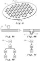
- a first method 100 for manufacturing a punctured filter plate according to the present invention and the resulting punctured filter plate 20 will be described with respect to figures 6 to 7B and 10 .
- the method 100 comprises providing 110 a metal foil 30 having a thickness T o between 100 ⁇ m and 400 ⁇ m.
- the metal used is preferably aluminium or an alloy thereof.
- the metal foil 30 may have a thickness between 125 ⁇ m and 350 ⁇ m, the thickness particularly being at least 150 ⁇ m, more particularly at least 175 ⁇ m and most particularly at least 200 ⁇ m, the thickness particularly being at most 300 ⁇ m, more particularly at most 275 ⁇ m and most particularly at most 250 ⁇ m.
- the method 100 further comprises piercing 120 the metal foil 30 to obtain a plurality of openings 24 each having a smallest dimension D hi between 300 ⁇ m and 1,5 mm.
- the pierced openings may have a smallest dimension between 400 ⁇ m and 1 mm, the smallest dimension being particularly at least 500 ⁇ m and more particularly at least 600 ⁇ m, the smallest dimension being particularly at most 900 ⁇ m and more particularly at most 800 ⁇ m.
- the piercing may be obtained by various known techniques, such as punching, laser cutting, etc.
- FIG 7A A detail of such a pierced foil is shown in figure 7A .
- the pierced opening 24 is circular with a diameter D hi (i.e. a smallest dimension) of about 750 ⁇ m.
- the metal foil 30 has a thickness T o of about 250 ⁇ m.
- the method 100 further comprises either step 130 or step 135. Both of which are described below.
- the method 100 comprises cutting the metal foil 30 along a predetermined two-dimensional contour to obtain a precursor of the punctured filter plate 20.
- this two-dimensional contour is a circle as shown in figure 6 .
- this cutting may involve various known techniques, such as removing excess material (e.g. trimming), punching the disk from the foil, etc.
- the result of this step is a flat disk with large openings 24.
- the area around each opening 24 is stamped, preferably coined, to reduce the foil thickness to obtain small openings 25 having a smallest dimension D he comprised between 25 ⁇ m and 300 ⁇ m.
- the foil thickness is reduced to a reduced thickness T c comprised between 50 ⁇ m and 350 ⁇ m, the reduced thickness particularly being at least 75 ⁇ m and more particularly at least 100 ⁇ m, the reduced thickness particularly being at most 250 ⁇ m and more particularly at most 200 ⁇ m.
- the smallest dimension D he is comprised between 50 ⁇ m and 200 ⁇ m, the smallest dimension being particularly at least 70 ⁇ m, the smallest dimension being particularly at most 170 ⁇ m and more particularly at most 150 ⁇ m.
- FIG. 7B A detail of such a stamped metal foil is shown in figure 7B .
- the foil thickness T o is about 300 ⁇ m
- the reduced foil thickness T c is about 50 ⁇ m
- the opening 25 has a smallest dimension D he of about 100 ⁇ m.
- Figure 7B also illustrates that the stamping causes a depressed area 26 having a diameter D c of about 1,5 mm in the illustrated embodiment.
- This depression is a side-effect of the stamping tool and counter mold used and would be absent (or at least less outspoken) if a flat surface counter mold was used.
- This depression results in a total foil thickness T of about 400 ⁇ m in the illustrated embodiment.
- the final punctured filter plate 20 obtained with the method 100 with steps 130 and 140 is shown in top view in figure 6 .
- the openings 25 are uniformly distributed within an inner circular surface with diameter d i which is about 34 mm in the illustrated embodiment.
- the larger circles surrounding each opening 25 are the depressed areas 26 caused by the coining operation.
- the outer ring is free of openings which provides a larger surface area to contact with the stepped region 16 c .
- the outer diameter d o of the punctured filter plate 20 is about 38 mm in the illustrated embodiment.
- the values of d o , d i are naturally dependent on the dimensions of the cup-shaped body 12 and on the desired fluid flow rate.
- the openings 25 in punctured filter plate 20 could also be oblong slits as described above.
- step 120 was followed by steps 130 and 140, in another variant, step 120 is followed by steps 135 and 145.
- step 135 the entire metal foil 30 is stamped, in particular coined, in a single step to reduce the smallest dimension of the openings 24.
- Step 135 may also involve stamping at least the area of the foil within the predetermined two-dimensional contour which delimits the punctured filter plate. The stamping is similar as in step 140 with the difference that a much larger area is stamped. There are thus also no local depressions 26 as the entire foil is thinned.
- Step 145 is similar to step 130 in that this involves cutting the stamped metal foil 30 along a predetermined two-dimensional contour to obtain the punctured filter plate 20.
- this two-dimensional contour is a circle as shown in figure 6 .
- this cutting may involve various known techniques, such as removing excess material (e.g. trimming), punching the disk from the foil, etc.
- the result of this step is the punctured filter plate 20 as illustrated in figure 1 .
- a second method 200 for manufacturing a punctured filter plate according to the present invention and the resulting punctured filter plate 20' will be described with respect to figures 8 to 9B and 11 .
- the method 200 comprises providing 210 a metal foil 30 having a thickness T o between 100 ⁇ m and 400 ⁇ m.
- the metal used is preferably aluminium or an alloy thereof.
- the metal foil 30 may have a thickness between 125 ⁇ m and 350 ⁇ m, the thickness particularly being at least 150 ⁇ m, more particularly at least 175 ⁇ m and most particularly at least 200 ⁇ m, the thickness particularly being at most 300 ⁇ m, more particularly at most 275 ⁇ m and most particularly at most 250 ⁇ m.
- one or more tools 50 are used to locally on a plurality of locations on the metal foil.
- a tool 50 is schematically shown in figure 9A with a metal foil 30. By locally pushing onto the foil 30, a depression 27 is created as shown in figure 9B . If the tool 50 is pushed deep enough into the foil 30 (e.g. by deep drawing), the elongation of the foil 30 will exceed the elongation at break properties of the material (e.g. aluminium) thus causing a tear 28 to appear. As shown in figure 8 , the tool 50 used has an elongated head. This causes a valley like depression 27 to be formed with eventual tearing 28 at the opposing ends of the valley.
- Step 230 is similar to steps 130, 145 in that this involves cutting the metal foil 30 along a predetermined two-dimensional contour to obtain the punctured filter plate 20'.
- this two-dimensional contour is a circle as shown in figure 8 .
- this cutting may involve various known techniques, such as removing excess material (e.g. trimming), punching the disk from the foil, etc.
- the result of this step is the punctured filter plate 20' as illustrated in figure 8 .
Landscapes
- Engineering & Computer Science (AREA)
- Mechanical Engineering (AREA)
- Apparatus For Making Beverages (AREA)
Priority Applications (1)
| Application Number | Priority Date | Filing Date | Title |
|---|---|---|---|
| EP23208128.1A EP4552763A1 (de) | 2023-11-07 | 2023-11-07 | Verfahren zur herstellung einer punktierten filterplatte zur verwendung in einer getränkekapsel |
Applications Claiming Priority (1)
| Application Number | Priority Date | Filing Date | Title |
|---|---|---|---|
| EP23208128.1A EP4552763A1 (de) | 2023-11-07 | 2023-11-07 | Verfahren zur herstellung einer punktierten filterplatte zur verwendung in einer getränkekapsel |
Publications (1)
| Publication Number | Publication Date |
|---|---|
| EP4552763A1 true EP4552763A1 (de) | 2025-05-14 |
Family
ID=88731364
Family Applications (1)
| Application Number | Title | Priority Date | Filing Date |
|---|---|---|---|
| EP23208128.1A Pending EP4552763A1 (de) | 2023-11-07 | 2023-11-07 | Verfahren zur herstellung einer punktierten filterplatte zur verwendung in einer getränkekapsel |
Country Status (1)
| Country | Link |
|---|---|
| EP (1) | EP4552763A1 (de) |
Citations (5)
| Publication number | Priority date | Publication date | Assignee | Title |
|---|---|---|---|---|
| EP0309708B1 (de) * | 1987-10-01 | 1992-12-09 | Societe Des Produits Nestle S.A. | Filter, verwendbar in Patronen zur Herstellung von Getränken |
| EP0742691B1 (de) * | 1994-03-03 | 1998-09-23 | Maxs Ag | Topfförmiger dauerfiltereinsatz |
| WO2013039585A1 (en) | 2011-09-13 | 2013-03-21 | Conair Corporation | Brewed beverage appliance and method |
| US20170283163A1 (en) | 2016-04-02 | 2017-10-05 | Rebecca J. Gatewood | Beverage pod |
| WO2019204916A1 (en) | 2018-04-23 | 2019-10-31 | 2266170 Ontario Inc. | Capsules and other containers with optimized recycling attributes and methods for making same |
-
2023
- 2023-11-07 EP EP23208128.1A patent/EP4552763A1/de active Pending
Patent Citations (5)
| Publication number | Priority date | Publication date | Assignee | Title |
|---|---|---|---|---|
| EP0309708B1 (de) * | 1987-10-01 | 1992-12-09 | Societe Des Produits Nestle S.A. | Filter, verwendbar in Patronen zur Herstellung von Getränken |
| EP0742691B1 (de) * | 1994-03-03 | 1998-09-23 | Maxs Ag | Topfförmiger dauerfiltereinsatz |
| WO2013039585A1 (en) | 2011-09-13 | 2013-03-21 | Conair Corporation | Brewed beverage appliance and method |
| US20170283163A1 (en) | 2016-04-02 | 2017-10-05 | Rebecca J. Gatewood | Beverage pod |
| WO2019204916A1 (en) | 2018-04-23 | 2019-10-31 | 2266170 Ontario Inc. | Capsules and other containers with optimized recycling attributes and methods for making same |
Similar Documents
| Publication | Publication Date | Title |
|---|---|---|
| EP2210827B1 (de) | Kapsel mit abnehmbaren Einspritzmitteln | |
| EP3218128B1 (de) | Verfahren zur herstellung eines becherförmigen körpers für eine getränkekapsel | |
| TWI276582B (en) | Method for preparing a beverage from a capsule and device for carrying out the method | |
| HU225842B1 (en) | Capsule, method for preparing various beverage in the same machine and method for improving hygiene and reducing cross-contamination in the preparation of a baverage from a capsule | |
| EP3898201B1 (de) | Fertigungsverfahren zur herstellung von hermetischen einweglebensmittelbehältern unter verwendung eines siegelkopfes mit einem spezifischen profil mit einer rippe | |
| KR20150100726A (ko) | 일인분 캡슐 및 일인분 캡슐에 의한 음료 생산 방법 | |
| CN107107454B (zh) | 用于制造胶囊元件的方法和设备以及相关的胶囊元件 | |
| CN1640350A (zh) | 含有一份用于制备咖啡饮料的咖啡粉的储筒 | |
| HU216484B (hu) | Berendezés és eljárás perforáció alakítására termoplasztikus lapban | |
| WO2016075318A1 (en) | A method of forming a beverage capsule, a beverage capsule and a beverage preparation system | |
| WO2016075321A1 (en) | A method of forming a beverage capsule, a beverage capsule, a beverage preparation system and a set of tools | |
| KR20200038474A (ko) | 음료를 제조하기 위한 캡슐 및 시스템 | |
| EP4552763A1 (de) | Verfahren zur herstellung einer punktierten filterplatte zur verwendung in einer getränkekapsel | |
| KR102425041B1 (ko) | 캡슐 및 음료 제조 시스템 | |
| EP4495029A1 (de) | Getränkekapsel | |
| EP4553001A1 (de) | Getränkekapsel | |
| WO2016075316A1 (en) | A method of forming a cup-shaped body of a beverage capsule, a beverage capsule and a beverage preparation system | |
| KR20190033475A (ko) | 캡슐 및 음료 제조 시스템 | |
| EP3697696A1 (de) | Verfahren und vorrichtung zur herstellung eines ein produkt enthaltenden behälters und entsprechender behälter | |
| KR20190038557A (ko) | 음료를 제조하기 위한 시스템 | |
| KR102422867B1 (ko) | 음료 제조용 캡슐 | |
| WO2024023661A1 (en) | A multilayer film with different adhesion zones for sealing a capsule for making beverages | |
| HK1141773B (en) | Capsule with delaminatable injection means | |
| KR20240123318A (ko) | 개선된 시일을 갖는 음료 포드 시스템 | |
| HK1130747A1 (en) | Capsule for preparation of a beverage with a sealing member attached thereto and method of producing the same |
Legal Events
| Date | Code | Title | Description |
|---|---|---|---|
| PUAI | Public reference made under article 153(3) epc to a published international application that has entered the european phase |
Free format text: ORIGINAL CODE: 0009012 |
|
| STAA | Information on the status of an ep patent application or granted ep patent |
Free format text: STATUS: THE APPLICATION HAS BEEN PUBLISHED |
|
| AK | Designated contracting states |
Kind code of ref document: A1 Designated state(s): AL AT BE BG CH CY CZ DE DK EE ES FI FR GB GR HR HU IE IS IT LI LT LU LV MC ME MK MT NL NO PL PT RO RS SE SI SK SM TR |
|
| STAA | Information on the status of an ep patent application or granted ep patent |
Free format text: STATUS: REQUEST FOR EXAMINATION WAS MADE |
|
| 17P | Request for examination filed |
Effective date: 20251031 |