EP4552766A1 - Ensemble culbuteur, utilisation d'un ensemble culbuteur, moule de coulée et procédé de coulée - Google Patents
Ensemble culbuteur, utilisation d'un ensemble culbuteur, moule de coulée et procédé de coulée Download PDFInfo
- Publication number
- EP4552766A1 EP4552766A1 EP23208126.5A EP23208126A EP4552766A1 EP 4552766 A1 EP4552766 A1 EP 4552766A1 EP 23208126 A EP23208126 A EP 23208126A EP 4552766 A1 EP4552766 A1 EP 4552766A1
- Authority
- EP
- European Patent Office
- Prior art keywords
- lever
- rocker arm
- arm assembly
- core
- casting mold
- Prior art date
- Legal status (The legal status is an assumption and is not a legal conclusion. Google has not performed a legal analysis and makes no representation as to the accuracy of the status listed.)
- Withdrawn
Links
Images


Classifications
-
- B—PERFORMING OPERATIONS; TRANSPORTING
- B22—CASTING; POWDER METALLURGY
- B22C—FOUNDRY MOULDING
- B22C9/00—Moulds or cores; Moulding processes
- B22C9/10—Cores; Manufacture or installation of cores
- B22C9/108—Installation of cores
-
- B—PERFORMING OPERATIONS; TRANSPORTING
- B22—CASTING; POWDER METALLURGY
- B22C—FOUNDRY MOULDING
- B22C21/00—Flasks; Accessories therefor
- B22C21/12—Accessories
- B22C21/14—Accessories for reinforcing or securing moulding materials or cores, e.g. gaggers, chaplets, pins, bars
Definitions
- the present invention relates to a rocker arm assembly for fixing a core, in particular a sand core, inside a casting mold, comprising: a first lever, and a second lever that is set up to exert pressure on the (sand) core.
- the present invention also relates to the use of a rocker arm assembly, a casting mold, and a casting process.
- SPM casting is a metal casting process characterized by using (re-)usable metal molds and (sand) cores to shape at least partly internal passages in cast components.
- the molds typically comprise at least two parts, wherein the cores are being put into place before the two parts are placed together.
- the molten metal flows into a mold cavity and surrounds the at least one (sand) core while filling the mold cavity.
- the at least one (sand) core is removed from the casting leaving an internal passage in the casing.
- the casting mold contains a negative impression of the component to be cast as the molten metal will be poured or filled into the mold.
- (sand) cores are regularly used.
- (sand) cores are often used to create complex components of automobile parts, in particular engine parts.
- the (sand) core is specifically designed as the negative form of the complex interior structure of the component to be cast.
- the block contains complex internal (hollow) structures meant for example for housing the cylinders.
- a (sand) core can be used to generate these internal structures.
- (Sand) cores are usually made using sand and a binder, but some processes also use permanent cores made of metal.
- (Sand) cores are also used to produce further types of cavities in castings, such as cavities for liquid cooling in engine blocks and cylinder heads.
- the specifically produced (sand) cores are placed into a casting mold, in particular into a metal mold. Then the casting mold is closed and molten metal, typically iron, steel, bronze, brass, aluminum, magnesium alloys or various pot metal alloys, which often include lead, tin and zinc, is poured or filled into the mold. After being filled with liquid metal, the metal is undergoing a solidification process. The mold is then opened and the at least one core is subsequently removed, revealing a casting, which may be subject to further post-processing steps, especially of the surface of the cast component.
- molten metal typically iron, steel, bronze, brass, aluminum, magnesium alloys or various pot metal alloys, which often include lead, tin and zinc
- Core flotation leads to deviations in the dimensions of the cast component from the specifications, especially in the dimensions of the inner structures of the cast component, or even to breaking apart of the (sand) core and therefore to a failure of the cast process.
- chaplets are often made of the same metal as the casting, as some of the chaplet metal will be incorporated into the casting itself.
- the chaplet's surface must melt after having fulfilled its task of keeping the core in place. The design of chaplets is therefore a tricky metallurgical process and is avoided whenever possible since there is always the possibility of introducing weaknesses or casting defects into the cast part when using a chaplet.
- the present invention is faced with the problem of providing an improved device and method for fixing a (sand) core during a casting process, in particular during a semi-permanent mold casting process, which helps at least reducing the problem of core movement.
- a rocker arm assembly for fixing a core, in particular a sand core, inside a casting mold comprising: a first lever, and a second lever that is set up to exert pressure on the core, characterized in that, the second lever is connected to the first lever via a connection such that movement of the first lever, in particular a rotation of the first lever, in a first direction, leads to transmission of force to the second lever to exert pressure on the core.
- the rocker arm assembly helps avoiding core movement without introducing weaknesses or alterations into the material of the cast component by fixing the core using the two levers. Additionally, the rocker arm assembly is re-usable and can be repeatedly used with a (re-usable) casting mold to fix cores in numerous casting processes, in particular in semi-permanent mold casting processes. At the same time, the rocker arm assembly is relatively simple in construction and therefore itself low error-prone as well as cost-effective.
- the first lever of the rocker arm assembly is preferably movably mounted, preferably using bearings.
- the bearings can for example be at least partly arranged on the casting mold.
- the second lever of the rocker arm assembly is set up to exert pressure on the core.
- the core is fixed inside the casting mold, which means it is held in position, especially during the casting process when molten metal is poured or filled into the casting mold. This way core movement can be significantly reduced or even prevented.
- the first lever of the rocker arm assembly is preferably set up to transfer the force generated by its movement via the connection to the second lever, which is preferably set up to then translate the force to exerting pressure on the sand core.
- This can be achieved, preferably, by movement, in particular by rotation, of the second lever caused by the movement, in particular by the rotation, of the first lever.
- the second lever is connected to the first lever via a connection such that movement, in particular rotation, of the first lever in a first direction is translated to movement, in particular rotation, of the second lever, in particular in a direction different to the direction of movement of the first lever, to exert pressure on the core.
- the connection is preferably set up accordingly.
- the direction of the force of the first lever caused by the movement, in particular by the rotation, of the first lever in the first direction, can be changed in a direction suited for fixation of a core, in particular of the sand core, and thus fixing the core by exerting pressure on it.
- the rocker arm assembly therefore In particular is set up to translate the force, with which the first lever is moved or driven, into a force, with which the second lever is driven, namely into the direction of the core to exert pressure on it.
- the first lever and/or the second lever preferably comprise metal as a material, for example high temperature steel or a high temperature steel alloy, so that they are durable and can endure several casting processes without changing form or losing functionality.
- the second lever is connected to the first lever via the connection such that movement, in particular the rotation, of the first lever in a second direction, which can be opposite to the first direction, causes the second lever to not exert pressure on the (sand) core (anymore), for example by not transferring force to the second lever in the direction towards the core (anymore).
- the core can easily be removed from the casting mold, for example by knocking or washing the sand out of the mold.
- the second lever is connected to the first lever via the connection such that when the first lever is not moved, in particular rotated, in the first direction (anymore), the second lever is caused to not exert pressure on the core (anymore).
- the second lever can be caused to not exert pressure on the core anymore, e.g. the pressure on the core can be released, for example by moving, in particular rotating, the first lever in a direction opposite to the first direction and also moving, in particular rotating, the second lever in a direction which is opposite to the movement causing the second lever to exert pressure on the core, or by just not transferring force on the first lever along the first direction anymore, in particular without moving the first lever in the opposite direction.
- rocker arm assembly or an embodiment thereof for fixing a (sand) core inside a casting mold, in particular in a (re-usable) metal casting mold.
- the aforementioned rocker arm assembly or an embodiment thereof is used for fixing a core, in particular a sand core, inside a casting mold for casting a component of a vehicle, especially an automobile, for example an engine block.
- a casting mold in particular a (re-usable) metal casting mold, comprising at least one aforementioned rocker arm assembly or an embodiment thereof.
- a casting process in particular a semi-permanent mold casting process, comprising the steps of: providing a casting mold, preferably an aforementioned casting mold, preferably a (re-usable) metal casting mold comprising at least two parts, or an embodiment thereof, and a core, in particular a sand core, inside the casting mold, closing the casting mold, wherein via at least one trigger mechanism of at least one rocker arm assembly, preferably at least one aforementioned rocker arm assembly or an embodiment thereof, a first lever is moved, in particular rotated, in a first direction, whereby force is transferred to a second lever so that the second lever exerts pressure on the core, pouring or filling liquid metal into the casting mold, optionally allowing the liquid metal to at least partially solidify, and opening the casting mold, wherein the pressure exerted on the core by the second lever is released.
- the first lever is moved, in particular rotated, in a first direction whereby the second lever connected to the first lever is moved to exert pressure on the core.
- the second lever is connected to the first lever via a connection.
- the pressure exerted on the core by the second lever can be released for example with the aid of a counterweight, which may be arranged at or on the first lever or the second lever.
- rocker arm assembly the use of a rocker arm assembly, the casting mold and the casting process are described below, wherein the various embodiments can be combined with one another and apply accordingly to embodiments of the rocker arm assembly, the use of a rocker arm assembly, the casting mold, and the casting process, in particular the semi-permanent mold casting process.
- the first lever is a shaft that is rotatably mounted, and the second lever is connected to the shaft via the connection such that rotation of the shaft in the first direction leads to transmission of force to the second lever to exert pressure on the core.
- the second lever is moved to exert pressure on the core.
- the shaft of the rocker arm assembly is rotatably mounted, for example bearings are used for mounting the shaft.
- the bearings can for example be at least partly arranged on the casting mold.
- the shaft is preferably set up to transfer its rotational force via the connection to the second lever.
- the connection is preferably setup accordingly.
- the rocker arm assembly according to this embodiment is therefore in particular set up to translate the rotational force, with which the shaft is driven, into a force, with which the second lever is driven, into the direction of the core to exert pressure on it.
- the first direction into which the first lever is moved preferably is a first rotational direction according to the afore-described first embodiment of the rocker arm assembly.
- the second lever comprises a first arm and a second arm, wherein the first arm is connected to the first lever via the connection and the second arm is set up to exert pressure on the core, and wherein the first arm and the second arm are connected via a joint.
- the rocker arm assembly allows for a greater flexibility in changing the direction of the force transferred from the first lever to the second lever as the second lever comprises two arms which thanks to their connection via the joint can themselves change the direction of the force transferred to the second lever.
- the rocker arm assembly and especially the first lever is set up to translate the movement of the first lever, for example the rotation of the shaft used as first lever, in the first direction to movement of the first arm of the second lever via the connection.
- the joint is preferably set up to transfer this movement of the first am of the second lever to movement of the second arm of the second lever to exert pressure on the core.
- a trigger mechanism is arranged at or on the first lever in such a way that by triggering the trigger mechanism the first lever is moved in the first direction.
- fixing of the core can be triggered by another process or action, for example a process or action linked to a casting process. This helps automatizing fixing the sand core inside the casting mold, especially during a casting process.
- the first lever is a shaft, preferably by triggering the trigger mechanism the shaft is moved in the first direction, which preferably is a rotational direction.
- the trigger mechanism comprises a push plate arranged at or on the first lever in such a way that by pushing the push plate the first lever is moved in the first direction.
- a rather simple and low error-prone mechanism can be used as a trigger mechanism to trigger the movement of the first lever in the first direction and eventually causing the second lever to exert pressure on the core thereby fixing the core in the casting mold.
- Pushing the push plate can be achieved by a variety of different processes such as an element, for example an element fixed to the casting mold, pushing the push plate. This can be achieved, for example, by moving at least the part of the rocker arm assembly containing the push plate in direction towards at least a part of the casting mold or vice versa.
- the trigger mechanism comprises a push plate arranged at or on the first lever, which can be a shaft, in such a way that by pushing the push plate the first lever is moved, preferentially rotated, in a first rotational direction.
- the rocker arm assembly comprises fastening means for at least partly arranging the rocker arm assembly on the casting mold.
- the rocker arm assembly can be securely mounted to the casting mold.
- at least a first part of the rocker arm assembly is arranged on at least a first part of the casting mold while other parts of the rocker arm assembly are arranged on further parts of the casting mold.
- at least the first lever possibly with the aid of respective bearings, is arranged on a side part of the casting mold.
- the second lever or the connection between the first and the second lever can also be arranged at or on this side part of the casting mold or solely be connection to the first lever and not be arranged onto (a part of) the casting mold itself.
- a counterweight is arranged at or on the first lever or at or on the second lever.
- the counterweight is arranged and constructed in such a way that it causes the second lever to release the pressure exerted on the core once the first lever is not moved in the first direction anymore or moved in a second direction, which can be opposite the first direction, so that no force causing the second lever to exert pressure on the core is transferred to the second lever anymore.
- the core can easily be removed from the casting mold, for example by knocking or washing the (sand) core out of the mold.
- the counterweight can be arranged on the second lever, for example at the end opposite the core of the second lever. Else, the counterweight can be arranged on the first lever, for example at the end opposite the connection of the first lever.
- the casting mold comprises at least a center part and a first side part and/or a second side part, wherein the first side part and the second side part are preferably arranged on opposite sides of the center part, and one rocker arm assembly is arranged at or on the first side part and/or the second side part.
- the at least one rocker arm assembly comprises a trigger mechanism arranged at or on the first lever, and the trigger mechanism is arranged such that closing the casting mold by moving at least one of the side parts in the direction of the center part causes a respective movement of the first lever of the rocker arm assembly in the first direction.
- closing the casting mold can be used to cause the rocker arm assembly to fix the core before a casting process is started and molten metal is poured or filled into the closed casting mold.
- the at least one rocker arm assembly is configured such that when no more force is transferred by the respective first lever to the respective second lever, for example when the first lever is not moved in the first direction causing the second lever to exert pressure on the core, and/or the casting mold is opened, in particular by moving at least one of the side parts away from the center part, the pressure exerted on the core by the second lever is released.
- the respective trigger mechanism of the rocker arm assembly arranged on a side part is arranged in such a way that closing or opening the mold by moving the side part towards or away from the center part causes the second lever to exert or release pressure on the (sand) core.
- a counterweight can be arranged at or on the respective first lever or second lever of each of the rocker arm assemblies causing the second lever to release the pressure on the (sand) core.
- the respective trigger mechanism can be triggered for example by pushing a push plate comprised by the trigger mechanism, in particular due to a pushing element arranged on the center part such that when the side part is moved towards the center part and thereby closing the casting mold, the pushing element pushes the push plate whereby the first lever is caused to move in the first direction and transferring a force to the second lever.
- the at least one pushing element comprises adjusting means for adjusting the force exerted to the push plate.
- the trigger mechanism may be individually adjusted with regard to the specific (sand) core used.
- Fig. 1 depicts an exemplary embodiment of a casting mold 4 with a rocker arm assembly 2 in a schematic and perspective view.
- the casting mold 4 of Fig. 1 is shown from another perspective.
- the rocker arm assembly 2 is used for fixing a sand core 6 inside the casting mold 4.
- the casting mold 4 is built up from different (metal) parts 4a, 4b, which can be moved with respect to each other to open and close the casting mold.
- the casting mold comprises at least a center part 4a and a first side part 4b.
- the casting mold 4 can further comprise a second side part (not shown) and each of the first side part 4b and the second side part can be arranged on opposite sides of the center part 4a.
- first side part 4a and the second side part At or on each of the first side part 4a and the second side part one rocker arm assembly 2 can be arranged, where here only one rocker arm assembly 2 is shown on the first side part 4b.
- the first side part 4b and the second side part (not shown) can be constructed as sliders so that by sliding the parts in the direction of the center part 4a the casting mold 4 can be closed and by sliding the parts in the opposite direction, thus away from the center part 4a, the casting mold 4 can be opened.
- the rocker arm assembly 2 comprises a first lever 22, which is constructed as a shaft 22a in this example, and a second lever 24, which is set up to exert pressure on the sand core 6.
- the second lever 24 is connected to the first lever 22 via a connection 26, such that movement of the first lever 22 in a first direction leads to transmission of force to the second lever 24 to exert pressure on the sand core 6.
- the second lever 24 comprises a first arm 24a and a second arm 24b, wherein the first arm 24a is connected to the first lever 22 via the connection 26 and the second arm 24b is set up to exert pressure on the sand core 6 and the arms 24a, 24b are connected via a joint 28.
- the joint 28 comprises a screw 28a connecting the first arm 24a and the second arm 24a such that they can be moved around the joint 28 relatively to each other.
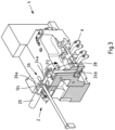
- Fig. 3 shows a schematic sectional view of the casting mold 4 of Fig. 1 and 2 .
- the casting mold 4 is only partly shown and can compose more than the shown parts, or the shown parts, such as the center part 4a, are only partly shown.
- the first lever 22 as a shaft 22a is rotatably mounted with the aid of bearings 12a-c.
- the rocker arm assembly 2 is arranged on the first side part 4b.
- the rocker arm assembly 2 includes fastening means 8 to secure the rocker arm assembly 2 to the side part 4b.
- the fastening means 8 in this example comprise a plate 10 and screws 14 to secure the plate 10 onto the side part 4b.
- the bearings 12a-c are arranged on the plate 10.
- the second lever 24 is connected to the shaft 22a via the connection 26 such that rotation of the shaft 22a in the first direction leads to transmission of force to the second lever 24 to exert pressure on the sand core 6.
- connection 26 comprising a pin 26a arranged on the outer circumference of the shaft 22a (see Fig. 3 ). Due to the pin 26a the first arm 24a and thanks to the joint 28 also the second arm 24b are moved in a rotational manner (arrow P2 in Fig. 3 ) around the joint 28 and in a direction towards the sand core 6 to exert pressure on it. Thus, fixing the sand core 6 is achieved due to the movement of the first lever 22 in the first direction.
- a trigger mechanism 16 is arranged on the end of the lever 22 opposite the connection 26.
- the trigger mechanism 16 is arranged on the first lever 22 in such a way that by triggering the trigger mechanism 16 the first lever 22 is moved in the first direction.
- the trigger mechanism 16 comprises a push plate 16a arranged at the end of the first lever 22 opposite the connection 26 in such a way that by pushing the push plate 16a the first lever 22 is moved in the first direction: the shaft 22a as first lever 22 is rotated in the first rotational direction P1 when the push plate 16a is pushed against from the direction of the center part 4a.
- the trigger mechanism 16, i.e. the push plate 16a, is arranged such that closing the casting mold 4 by moving the side part 4b in the direction of the center part 4a causes a movement of the first lever 22 in the first direction: the side part 4a comprises a pushing element 18, here formed as a protruding screw 18a, which pushes the push plate 16a so that the shaft 22a is rotated in the first rotational direction P1 when the side part 4b is moved towards the center part 4a of the casting mold and thereby closing the casting mold 4.
- the rocker arm assembly 2 is configured such that when no more force is transferred by the first lever 22 to the second lever 24, for example when the first lever 22 is not moved in the first direction (anymore), the pressure exerted on the sand core by the second lever 24 is released.
- This can be achieved for example by opening the casting mold 4 due to moving the first side part 4b in a direction away from the center part 4a.
- the trigger mechanism 16 i.e. the push plate 16a in this example, is not being triggered anymore and hence the shaft 22a as the first lever 22 does not transfer force anymore to the second lever 24 to exert pressure on the sand core 6.
- the release of the pressure on the sand core 6 enacted by the second lever 24 can be assisted or caused by a counterweight 20.
- the counterweight 20 is, as can be seen in particular in Fig. 3 , is arranged at the second lever 24, namely at the end of first arm 24a of the second lever 24 opposing the joint 28. This way the counterweight 20 enacts a force at least partly in the opposite direction to the force transferred from the first lever 22 to the second lever 24 when the first lever 22 is moved in the first direction.
- a counterweight 20 is arranged at or on the first lever 22.
- the push plate 16a itself can act as a counterweight 20 leading to a movement of the push plate 16a in a direction opposite to the first rotational direction P1 when the push plate 16a is not pushed in a direction towards the side part 4b anymore, e.g. when the casting mold 4 is opened by moving the side part 4b away from the center part 4a.
- the sand core 6 can be easily removed when the casting mold 4 is opened.
Landscapes
- Engineering & Computer Science (AREA)
- Mechanical Engineering (AREA)
- Molds, Cores, And Manufacturing Methods Thereof (AREA)
Priority Applications (2)
| Application Number | Priority Date | Filing Date | Title |
|---|---|---|---|
| EP23208126.5A EP4552766A1 (fr) | 2023-11-07 | 2023-11-07 | Ensemble culbuteur, utilisation d'un ensemble culbuteur, moule de coulée et procédé de coulée |
| PCT/IB2024/060629 WO2025099533A1 (fr) | 2023-11-07 | 2024-10-29 | Ensemble culbuteur, utilisation d'un ensemble culbuteur, moule de coulée et procédé de coulée |
Applications Claiming Priority (1)
| Application Number | Priority Date | Filing Date | Title |
|---|---|---|---|
| EP23208126.5A EP4552766A1 (fr) | 2023-11-07 | 2023-11-07 | Ensemble culbuteur, utilisation d'un ensemble culbuteur, moule de coulée et procédé de coulée |
Publications (1)
| Publication Number | Publication Date |
|---|---|
| EP4552766A1 true EP4552766A1 (fr) | 2025-05-14 |
Family
ID=88731655
Family Applications (1)
| Application Number | Title | Priority Date | Filing Date |
|---|---|---|---|
| EP23208126.5A Withdrawn EP4552766A1 (fr) | 2023-11-07 | 2023-11-07 | Ensemble culbuteur, utilisation d'un ensemble culbuteur, moule de coulée et procédé de coulée |
Country Status (2)
| Country | Link |
|---|---|
| EP (1) | EP4552766A1 (fr) |
| WO (1) | WO2025099533A1 (fr) |
Citations (6)
| Publication number | Priority date | Publication date | Assignee | Title |
|---|---|---|---|---|
| JPS59218240A (ja) * | 1983-05-27 | 1984-12-08 | Nissan Motor Co Ltd | 中子セツト装置 |
| US4765389A (en) * | 1986-01-24 | 1988-08-23 | Dansk Industri Syndikat A/S | Core setter |
| US20040011499A1 (en) * | 2000-11-30 | 2004-01-22 | Knudsen Soren Danis | Core setter for matchplate moulding machine |
| EP1927415A1 (fr) * | 2006-12-01 | 2008-06-04 | Sintokogio, Ltd. | Procédé de coulée, ensemble de moule supérieur et procédé de fixation du noyau sur le moule supérieur |
| CN112756560A (zh) * | 2020-12-31 | 2021-05-07 | 金华市宝琳科技股份有限公司 | 一种新型盐芯自动夹放装置 |
| US20220347904A1 (en) * | 2019-12-04 | 2022-11-03 | Shibaura Machine Co., Ltd. | Hybrid core driving device and molding machine |
-
2023
- 2023-11-07 EP EP23208126.5A patent/EP4552766A1/fr not_active Withdrawn
-
2024
- 2024-10-29 WO PCT/IB2024/060629 patent/WO2025099533A1/fr active Pending
Patent Citations (6)
| Publication number | Priority date | Publication date | Assignee | Title |
|---|---|---|---|---|
| JPS59218240A (ja) * | 1983-05-27 | 1984-12-08 | Nissan Motor Co Ltd | 中子セツト装置 |
| US4765389A (en) * | 1986-01-24 | 1988-08-23 | Dansk Industri Syndikat A/S | Core setter |
| US20040011499A1 (en) * | 2000-11-30 | 2004-01-22 | Knudsen Soren Danis | Core setter for matchplate moulding machine |
| EP1927415A1 (fr) * | 2006-12-01 | 2008-06-04 | Sintokogio, Ltd. | Procédé de coulée, ensemble de moule supérieur et procédé de fixation du noyau sur le moule supérieur |
| US20220347904A1 (en) * | 2019-12-04 | 2022-11-03 | Shibaura Machine Co., Ltd. | Hybrid core driving device and molding machine |
| CN112756560A (zh) * | 2020-12-31 | 2021-05-07 | 金华市宝琳科技股份有限公司 | 一种新型盐芯自动夹放装置 |
Also Published As
| Publication number | Publication date |
|---|---|
| WO2025099533A1 (fr) | 2025-05-15 |
Similar Documents
| Publication | Publication Date | Title |
|---|---|---|
| CN101547760B (zh) | 用于铸造一种铸成件的铸造模具以及该铸造模具的应用 | |
| US6860315B2 (en) | Green sand casting method and apparatus | |
| CN109158536A (zh) | 一种预防汽车球铁转向器壳体铸件泄漏的铸造工艺 | |
| EP4552766A1 (fr) | Ensemble culbuteur, utilisation d'un ensemble culbuteur, moule de coulée et procédé de coulée | |
| CN102527997A (zh) | 受控压力铸造 | |
| JP2008212942A (ja) | シリンダブロックの製造方法 | |
| WO2006044713A2 (fr) | Technique de plaquage d'un element d'insertion pour des procedes de coulage de precision | |
| CN102239018B (zh) | 用于压铸的设备、此设备的用法以及压铸方法 | |
| KR100509995B1 (ko) | 외부 주형부 및 내부에 삽입된 주형 재료 코어를 포함하는주형 | |
| JP2637813B2 (ja) | 金型鋳造法 | |
| FI92162C (fi) | Menetelmä metallikappaleiden valamiseksi paineen alla häviävän mallin tekniikkaa käyttäen | |
| US20240307952A1 (en) | Method and cast part production system for producing an electric motor housing, and electric motor | |
| CN116867584A (zh) | 用于制造电机壳体的方法及铸件制造设备和电机 | |
| EP1779943B1 (fr) | Procédé et dispositif de fabrication des carters de vilebequins cylindriques en métal léger das les moules en sable | |
| US3685569A (en) | Method for gravity pressure permanent molding | |
| JP3122298B2 (ja) | カムシャフト及びその製造方法 | |
| JPS6325305A (ja) | Al合金製ロツカア−ムの製造方法 | |
| JP2026064337A (ja) | 異材接合体、溶接部品、及び鋳ぐるみ方法 | |
| JP2002333040A (ja) | 車両用ディスクブレーキのキャリパボディ及びその製造方法 | |
| SU1065079A1 (ru) | Кокиль | |
| CN112605347B (zh) | 一种汽车电机端盖模具的嵌件锁紧装置 | |
| KR100232079B1 (ko) | 자동차용 파워스티어링 베인 펌프 하우징 주조공법 | |
| US11014149B2 (en) | Ingot mold and method for producing a component | |
| JPS6213237A (ja) | 冷し金 | |
| JPH0421633Y2 (fr) |
Legal Events
| Date | Code | Title | Description |
|---|---|---|---|
| PUAI | Public reference made under article 153(3) epc to a published international application that has entered the european phase |
Free format text: ORIGINAL CODE: 0009012 |
|
| STAA | Information on the status of an ep patent application or granted ep patent |
Free format text: STATUS: THE APPLICATION HAS BEEN PUBLISHED |
|
| AK | Designated contracting states |
Kind code of ref document: A1 Designated state(s): AL AT BE BG CH CY CZ DE DK EE ES FI FR GB GR HR HU IE IS IT LI LT LU LV MC ME MK MT NL NO PL PT RO RS SE SI SK SM TR |
|
| STAA | Information on the status of an ep patent application or granted ep patent |
Free format text: STATUS: THE APPLICATION IS DEEMED TO BE WITHDRAWN |
|
| 18D | Application deemed to be withdrawn |
Effective date: 20251115 |