EP4553074A1 - Aminverbindung und organisches elektrolumineszenzelement, elektronische ausrüstung und elektronisches element damit - Google Patents
Aminverbindung und organisches elektrolumineszenzelement, elektronische ausrüstung und elektronisches element damit Download PDFInfo
- Publication number
- EP4553074A1 EP4553074A1 EP23835581.2A EP23835581A EP4553074A1 EP 4553074 A1 EP4553074 A1 EP 4553074A1 EP 23835581 A EP23835581 A EP 23835581A EP 4553074 A1 EP4553074 A1 EP 4553074A1
- Authority
- EP
- European Patent Office
- Prior art keywords
- group
- unsubstituted
- phenyl
- compound
- substituted
- Prior art date
- Legal status (The legal status is an assumption and is not a legal conclusion. Google has not performed a legal analysis and makes no representation as to the accuracy of the status listed.)
- Pending
Links
Images





Classifications
-
- H—ELECTRICITY
- H10—SEMICONDUCTOR DEVICES; ELECTRIC SOLID-STATE DEVICES NOT OTHERWISE PROVIDED FOR
- H10K—ORGANIC ELECTRIC SOLID-STATE DEVICES
- H10K85/00—Organic materials used in the body or electrodes of devices covered by this subclass
- H10K85/60—Organic compounds having low molecular weight
- H10K85/631—Amine compounds having at least two aryl rest on at least one amine-nitrogen atom, e.g. triphenylamine
- H10K85/636—Amine compounds having at least two aryl rest on at least one amine-nitrogen atom, e.g. triphenylamine comprising heteroaromatic hydrocarbons as substituents on the nitrogen atom
-
- H—ELECTRICITY
- H10—SEMICONDUCTOR DEVICES; ELECTRIC SOLID-STATE DEVICES NOT OTHERWISE PROVIDED FOR
- H10K—ORGANIC ELECTRIC SOLID-STATE DEVICES
- H10K50/00—Organic light-emitting devices
- H10K50/80—Constructional details
- H10K50/85—Arrangements for extracting light from the devices
- H10K50/858—Arrangements for extracting light from the devices comprising refractive means, e.g. lenses
-
- C—CHEMISTRY; METALLURGY
- C07—ORGANIC CHEMISTRY
- C07D—HETEROCYCLIC COMPOUNDS
- C07D263/00—Heterocyclic compounds containing 1,3-oxazole or hydrogenated 1,3-oxazole rings
- C07D263/52—Heterocyclic compounds containing 1,3-oxazole or hydrogenated 1,3-oxazole rings condensed with carbocyclic rings or ring systems
- C07D263/54—Benzoxazoles; Hydrogenated benzoxazoles
- C07D263/56—Benzoxazoles; Hydrogenated benzoxazoles with only hydrogen atoms, hydrocarbon or substituted hydrocarbon radicals, directly attached in position 2
- C07D263/57—Aryl or substituted aryl radicals
-
- C—CHEMISTRY; METALLURGY
- C07—ORGANIC CHEMISTRY
- C07D—HETEROCYCLIC COMPOUNDS
- C07D277/00—Heterocyclic compounds containing 1,3-thiazole or hydrogenated 1,3-thiazole rings
- C07D277/60—Heterocyclic compounds containing 1,3-thiazole or hydrogenated 1,3-thiazole rings condensed with carbocyclic rings or ring systems
- C07D277/62—Benzothiazoles
- C07D277/64—Benzothiazoles with only hydrocarbon or substituted hydrocarbon radicals attached in position 2
- C07D277/66—Benzothiazoles with only hydrocarbon or substituted hydrocarbon radicals attached in position 2 with aromatic rings or ring systems directly attached in position 2
-
- C—CHEMISTRY; METALLURGY
- C07—ORGANIC CHEMISTRY
- C07D—HETEROCYCLIC COMPOUNDS
- C07D413/00—Heterocyclic compounds containing two or more hetero rings, at least one ring having nitrogen and oxygen atoms as the only ring hetero atoms
- C07D413/02—Heterocyclic compounds containing two or more hetero rings, at least one ring having nitrogen and oxygen atoms as the only ring hetero atoms containing two hetero rings
- C07D413/12—Heterocyclic compounds containing two or more hetero rings, at least one ring having nitrogen and oxygen atoms as the only ring hetero atoms containing two hetero rings linked by a chain containing hetero atoms as chain links
-
- C—CHEMISTRY; METALLURGY
- C07—ORGANIC CHEMISTRY
- C07D—HETEROCYCLIC COMPOUNDS
- C07D413/00—Heterocyclic compounds containing two or more hetero rings, at least one ring having nitrogen and oxygen atoms as the only ring hetero atoms
- C07D413/14—Heterocyclic compounds containing two or more hetero rings, at least one ring having nitrogen and oxygen atoms as the only ring hetero atoms containing three or more hetero rings
-
- C—CHEMISTRY; METALLURGY
- C07—ORGANIC CHEMISTRY
- C07D—HETEROCYCLIC COMPOUNDS
- C07D417/00—Heterocyclic compounds containing two or more hetero rings, at least one ring having nitrogen and sulfur atoms as the only ring hetero atoms, not provided for by group C07D415/00
- C07D417/02—Heterocyclic compounds containing two or more hetero rings, at least one ring having nitrogen and sulfur atoms as the only ring hetero atoms, not provided for by group C07D415/00 containing two hetero rings
- C07D417/12—Heterocyclic compounds containing two or more hetero rings, at least one ring having nitrogen and sulfur atoms as the only ring hetero atoms, not provided for by group C07D415/00 containing two hetero rings linked by a chain containing hetero atoms as chain links
-
- C—CHEMISTRY; METALLURGY
- C07—ORGANIC CHEMISTRY
- C07D—HETEROCYCLIC COMPOUNDS
- C07D417/00—Heterocyclic compounds containing two or more hetero rings, at least one ring having nitrogen and sulfur atoms as the only ring hetero atoms, not provided for by group C07D415/00
- C07D417/14—Heterocyclic compounds containing two or more hetero rings, at least one ring having nitrogen and sulfur atoms as the only ring hetero atoms, not provided for by group C07D415/00 containing three or more hetero rings
-
- C—CHEMISTRY; METALLURGY
- C07—ORGANIC CHEMISTRY
- C07D—HETEROCYCLIC COMPOUNDS
- C07D471/00—Heterocyclic compounds containing nitrogen atoms as the only ring hetero atoms in the condensed system, at least one ring being a six-membered ring with one nitrogen atom, not provided for by groups C07D451/00 - C07D463/00
- C07D471/02—Heterocyclic compounds containing nitrogen atoms as the only ring hetero atoms in the condensed system, at least one ring being a six-membered ring with one nitrogen atom, not provided for by groups C07D451/00 - C07D463/00 in which the condensed system contains two hetero rings
- C07D471/04—Ortho-condensed systems
-
- C—CHEMISTRY; METALLURGY
- C09—DYES; PAINTS; POLISHES; NATURAL RESINS; ADHESIVES; COMPOSITIONS NOT OTHERWISE PROVIDED FOR; APPLICATIONS OF MATERIALS NOT OTHERWISE PROVIDED FOR
- C09K—MATERIALS FOR MISCELLANEOUS APPLICATIONS, NOT PROVIDED FOR ELSEWHERE
- C09K11/00—Luminescent materials, e.g. electroluminescent or chemiluminescent
- C09K11/02—Use of particular materials as binders, particle coatings or suspension media therefor
- C09K11/025—Use of particular materials as binders, particle coatings or suspension media therefor non-luminescent particle coatings or suspension media
-
- G—PHYSICS
- G02—OPTICS
- G02B—OPTICAL ELEMENTS, SYSTEMS OR APPARATUS
- G02B5/00—Optical elements other than lenses
- G02B5/20—Filters
- G02B5/22—Absorbing filters
- G02B5/223—Absorbing filters containing organic substances, e.g. dyes, inks or pigments
-
- H—ELECTRICITY
- H10—SEMICONDUCTOR DEVICES; ELECTRIC SOLID-STATE DEVICES NOT OTHERWISE PROVIDED FOR
- H10K—ORGANIC ELECTRIC SOLID-STATE DEVICES
- H10K50/00—Organic light-emitting devices
- H10K50/10—OLEDs or polymer light-emitting diodes [PLED]
-
- H—ELECTRICITY
- H10—SEMICONDUCTOR DEVICES; ELECTRIC SOLID-STATE DEVICES NOT OTHERWISE PROVIDED FOR
- H10K—ORGANIC ELECTRIC SOLID-STATE DEVICES
- H10K50/00—Organic light-emitting devices
- H10K50/80—Constructional details
- H10K50/84—Passivation; Containers; Encapsulations
- H10K50/844—Encapsulations
-
- H—ELECTRICITY
- H10—SEMICONDUCTOR DEVICES; ELECTRIC SOLID-STATE DEVICES NOT OTHERWISE PROVIDED FOR
- H10K—ORGANIC ELECTRIC SOLID-STATE DEVICES
- H10K85/00—Organic materials used in the body or electrodes of devices covered by this subclass
- H10K85/60—Organic compounds having low molecular weight
- H10K85/649—Aromatic compounds comprising a hetero atom
- H10K85/653—Aromatic compounds comprising a hetero atom comprising only oxygen as heteroatom
-
- H—ELECTRICITY
- H10—SEMICONDUCTOR DEVICES; ELECTRIC SOLID-STATE DEVICES NOT OTHERWISE PROVIDED FOR
- H10K—ORGANIC ELECTRIC SOLID-STATE DEVICES
- H10K85/00—Organic materials used in the body or electrodes of devices covered by this subclass
- H10K85/60—Organic compounds having low molecular weight
- H10K85/649—Aromatic compounds comprising a hetero atom
- H10K85/655—Aromatic compounds comprising a hetero atom comprising only sulfur as heteroatom
-
- H—ELECTRICITY
- H10—SEMICONDUCTOR DEVICES; ELECTRIC SOLID-STATE DEVICES NOT OTHERWISE PROVIDED FOR
- H10K—ORGANIC ELECTRIC SOLID-STATE DEVICES
- H10K85/00—Organic materials used in the body or electrodes of devices covered by this subclass
- H10K85/60—Organic compounds having low molecular weight
- H10K85/649—Aromatic compounds comprising a hetero atom
- H10K85/657—Polycyclic condensed heteroaromatic hydrocarbons
-
- H—ELECTRICITY
- H10—SEMICONDUCTOR DEVICES; ELECTRIC SOLID-STATE DEVICES NOT OTHERWISE PROVIDED FOR
- H10K—ORGANIC ELECTRIC SOLID-STATE DEVICES
- H10K85/00—Organic materials used in the body or electrodes of devices covered by this subclass
- H10K85/60—Organic compounds having low molecular weight
- H10K85/649—Aromatic compounds comprising a hetero atom
- H10K85/657—Polycyclic condensed heteroaromatic hydrocarbons
- H10K85/6572—Polycyclic condensed heteroaromatic hydrocarbons comprising only nitrogen in the heteroaromatic polycondensed ring system, e.g. phenanthroline or carbazole
-
- H—ELECTRICITY
- H10—SEMICONDUCTOR DEVICES; ELECTRIC SOLID-STATE DEVICES NOT OTHERWISE PROVIDED FOR
- H10K—ORGANIC ELECTRIC SOLID-STATE DEVICES
- H10K85/00—Organic materials used in the body or electrodes of devices covered by this subclass
- H10K85/60—Organic compounds having low molecular weight
- H10K85/649—Aromatic compounds comprising a hetero atom
- H10K85/657—Polycyclic condensed heteroaromatic hydrocarbons
- H10K85/6574—Polycyclic condensed heteroaromatic hydrocarbons comprising only oxygen in the heteroaromatic polycondensed ring system, e.g. cumarine dyes
-
- H—ELECTRICITY
- H10—SEMICONDUCTOR DEVICES; ELECTRIC SOLID-STATE DEVICES NOT OTHERWISE PROVIDED FOR
- H10K—ORGANIC ELECTRIC SOLID-STATE DEVICES
- H10K85/00—Organic materials used in the body or electrodes of devices covered by this subclass
- H10K85/60—Organic compounds having low molecular weight
- H10K85/649—Aromatic compounds comprising a hetero atom
- H10K85/657—Polycyclic condensed heteroaromatic hydrocarbons
- H10K85/6576—Polycyclic condensed heteroaromatic hydrocarbons comprising only sulfur in the heteroaromatic polycondensed ring system, e.g. benzothiophene
Definitions
- the present invention relates to a compound and device suitable for a spontaneous light-emitting electronic device suitable for various display devices, particularly, an organic electroluminescent device (hereinafter, abbreviated as an organic EL device), and more specifically to an amine compound having a benzoazole structure and an organic EL device or electronic apparatus using the amine compound.
- an organic electroluminescent device hereinafter, abbreviated as an organic EL device
- C.W.Tang et al. (Eastman Kodak Company) have developed a stacked-structure device in which various roles are assigned to the materials and put an organic EL device using an organic material to practical use. They have stacked a phosphor capable of transporting electrons and an organic matter capable of transporting holes and caused their charges to emit light by injecting the charges into a layer of the phosphor, making it possible to achieve high luminance of 1000 cd/m 2 or more at a voltage of 10 V or less (see Patent Literature 1 and Patent Literature 2).
- Non-Patent Literature 1 a light-emitting element having a bottom emission structure that emits light from the bottom portion in an electroluminescent device in which an anode, a hole injection layer, a hole transport layer, a light-emitting layer, an electron transport layer, an electron injection layer, and a cathode are sequentially provided on a substrate.
- the light-emitting element having a top emission structure in which a metal having a high work function is used as an anode and light is emitted from the upper part has been used. While the area of the light-emitting unit is limited in the bottom emission structure in which light is extracted from the bottom portion having a pixel circuit, the light-emitting element having a top emission structure has an advantage that the light-emitting unit can be made wider because light is extracted from the upper part, which does not block the pixel circuit.
- a semi-transparent electrode formed of LiF/Al/Ag (see, for example, Non-Patent Literature 2), Ca/Mg (see, for example, Non-Patent Literature 3), LiF/MgAg, or the like, is used as a cathode.
- the current efficiency was 38 cd/A in the light-emitting element that includes no capping layer and uses Ir(ppy) 3 as a light-emitting material while the current efficiency was improved to be approximately 1.7 times, i.e., 64 cd/A, in the light-emitting element that uses ZnSe with a film thickness of 60 nm as a capping layer.
- the maximum transmittance and the maximum efficiency of the semi-transparent electrode and capping layer do not necessarily coincide and the maximum light extraction efficiency is determined by the interference effect (see, for example, Non-Patent Literature 3).
- a metal mask with high definition for forming a capping layer has been proposed, but the metal mask is distorted by heat when used under high-temperature conditions, which reduces the alignment accuracy. Therefore, ZnSe has a high melting point of 1100°C or more (see, for example, Non-Patent Literature 3) and cannot be deposited at an accurate position in the metal mask with high definition, which may affect the light-emitting element itself. Further, a capping layer formed of an inorganic matter is not suitable for use because it affects the light-emitting element even if it is deposited by a sputtering method.
- Alq 3 tris(8-hydroxyquinoline)aluminum (hereinafter, abbreviated as Alq 3 ) as a capping layer for adjusting the refractive index
- Alq 3 is known as an organic EL material that is generally used as a green light-emitting material or an electron transport material, but causes a problem of reduced color purity and reduced light extraction efficiency in the case of a blue light-emitting element because it has weak absorption around 450 nm used in the blue light-emitting material.
- devices prepared using an existing capping layer also has a problem of reduced color purity and reduced light extraction efficiency because light at a wavelength from 400 nm to 410 nm in sunlight passes therethrough and affects the materials inside the device.
- a material having a high refractive index, a low extinction coefficient, and excellent stability in a thin-film state and durability is desired as a material of a capping layer.
- An object of the present invention is to provide an organic EL device that includes a capping layer formed of a material having (1) a high refractive index, (2) favorable stability in a thin-film state, (3) excellent durability, (4) excellent light resistance, and (5) no absorption in blue, green, and red wavelength regions in order to improve the device properties of the organic EL device and significantly improve the light extraction efficiency.
- Examples of the physical properties of the material of the capping layer suitable for the present invention include (1) having a high refractive index, (2) being depositable, (3) being stable in a thin-film state, and (4) having a high glass transition temperature. Further, examples of the physical properties of the device suitable for the present invention include (1) having a high light extraction efficiency, (2) having no reduced color purity, (3) causing light to be transmitted therethrough without change over time, and (4) having a long lifetime.
- an arylamine material has excellent stability in a thin-film state and excellent durability
- selected a specific amine compound having a high refractive index and a benzoazole structure as a material having high absorbance at a wavelength from 400 nm to 410 nm in the absorption spectrum of 10 -5 mol/L
- prepared an organic EL device using the selected compound as a material for forming a capping layer and intensively evaluated the properties of the device to complete the present invention.
- an amine compound represented by the following general formula (A) an organic EL device or electronic apparatus using the amine compound.
- the amine compound according to the present invention (1) has a high absorption coefficient, (2) has a high refractive index in the wavelength range of 450 nm to 750 nm, (3) is depositable, (4) is stable in a thin-film state, and (5)has high heat resistance, and using it as a capping layer having a refractive index higher than that of a semi-transparent electrode, which is provided outside a transparent or semi-transparent electrode of the organic EL device, makes it possible to obtain an organic EL device that is capable of significantly improving the light extraction efficiency and prevents the materials inside the device from deteriorating.
- the amine compound according to the present invention is a novel compound represented by the general formula (A), (B), or (C), and benzoazole derivatives that are the main skeletons of these compounds can be synthesized by known methods (see, for example, Patent Literature 4).
- the amine compound according to the present invention can be synthesized by subjecting the synthesized halogenated benzoazole derivative and arylamine to a coupling reaction using a copper catalyst, a palladium catalyst, or the like.
- the amine compound according to the present invention can be similarly synthesized by obtaining a boronic acid ester derivative from the halogenated benzoazole derivative and then subjecting the obtained derivative to a coupling reaction with halogenated arylamine (see, for example, Non-Patent Literature 5 and Non-Patent Literature 6).
- Ar 2 and Ar 3 in the general formula (A), (B), or (C) may be the same as or different from each other and each represent a substituted or unsubstituted aromatic hydrocarbon group, a substituted or unsubstituted aromatic heterocyclic group, or a substituted or unsubstituted fused polycyclic aromatic group.
- the "aromatic hydrocarbon group", "aromatic heterocyclic group”, or “fused polycyclic aromatic group” in the "substituted or unsubstituted aromatic hydrocarbon group", “substituted or unsubstituted aromatic heterocyclic group”, or “substituted or unsubstituted fused polycyclic aromatic group” represented by Ar 2 and Ar 3 in the general formula (A), (B), or (C) is specifically selected from the group consisting of an aryl group having 6 to 30 carbon atoms and a heteroaryl group having 2 to 20 carbon atoms in addition to a phenyl group, a biphenylyl group, a terphenylyl group, a naphthyl group, an anthracenyl group, a phenanthrenyl group, a fluorenyl group, a spirobifluorenyl group, an indenyl group, a pyrenyl group,
- specific examples of the "substituent group" in the "substituted aromatic hydrocarbon group", “substituted aromatic heterocyclic group” or “substituted fused polycyclic aromatic group” represented by Ar 2 and Ar 3 in the general formula (A), (B), or (C) include an aryl group having 6 to 30 carbon atoms and a heteroaryl group having 2 to 20 carbon atoms in addition to a deuterium atom, a cyano group, a nitro group; a halogen atom such as a fluorine atom, a chlorine atom, a bromine atom, and an iodine atom; a silyl group such as a trimethylsilyl group and a triphenylsilyl group; a linear or branched alkyl group having 1 to 6 carbon atoms such as a methyl group, an ethyl group, and a propyl group; a linear or branched
- substituent groups may be further substituted with the exemplified substituted groups. Further, these substituent groups and the substituted benzene ring or a plurality of substituent groups on the same benzene ring may be boded to each other via a single bond, a substituted or unsubstituted methylene group, an oxygen atom, or a sulfur atom to form a ring.
- an unsubstituted aromatic hydrocarbon group or an unsubstituted aromatic heterocyclic group is favorable, and an unsubstituted phenyl group, an unsubstituted naphthyl group, an unsubstituted dibenzofuranyl group, an unsubstituted dibenzothienyl group, an unsubstituted benzoxazolyl group, an unsubstituted benzothiazolyl group, an unsubstituted benzofuranyl group, an unsubstituted benzothienyl group, an unsubstituted phenanthryl group, or an unsubstituted quinolyl group is more favorable.
- a substituted or unsubstituted phenyl group, a substituted or unsubstituted biphenyl group, a substituted or unsubstituted naphthyl group, a substituted or unsubstituted furanyl group, or a substituted or unsubstituted thienyl group is favorable, an unsubstituted phenyl group, an unsubstituted biphenyl group, an unsubstituted naphthyl group, an unsubstituted furanyl group, or an unsubstituted thienyl group is more favorable, an unsubstituted phenyl group or an unsubstituted naphthyl group is more favorable, and an unsubstituted phenyl group or an unsubstituted 2-naphthyl group is still more favorable.
- Ar 1 in the general formula (A), (B), or (C) represents a substituted or unsubstituted benzoxazolyl group, a substituted or unsubstituted benzothiazolyl group, a substituted or unsubstituted benzofuranyl group, a substituted or unsubstituted benzothienyl group, a substituted or unsubstituted dibenzofuranyl group, or a substituted or unsubstituted dibenzothienyl group.
- Ar 1 represents a substituted or unsubstituted 2-benzoxazolyl group, a substituted or unsubstituted 2-benzothiazolyl group, a substituted or unsubstituted 2-benzofuranyl group, a substituted or unsubstituted 2-benzothienyl group, a substituted or unsubstituted 2-dibenzofuranyl group, a substituted or unsubstituted 2-dibenzothienyl group, a substituted or unsubstituted 3-dibenzofuranyl group, or a substituted or unsubstituted 3-dibenzothienyl group.
- Ar 1 represents an unsubstituted 2-benzoxazolyl group, an unsubstituted 2-benzothiazolyl group, an unsubstituted 2-benzofuranyl group, an unsubstituted 2-benzothienyl group, an unsubstituted 2-dibenzofuranyl group, an unsubstituted 2-dibenzothienyl group, an unsubstituted 3-dibenzofuranyl group, or an unsubstituted 3-dibenzothienyl group.
- examples of the "substituent group" in the "substituted benzoxazolyl group", “substituted benzothiazolyl group”, “substituted benzofuranyl group”, “substituted benzothienyl group”, “substituted dibenzofuranyl group”, or “substituted dibenzothienyl group” represented by Ar 1 in the general formula (A), (B), or (C) includes those shown for the "substituent group” in the "substituted aromatic hydrocarbon group", “substituted aromatic heterocyclic group", or “substituted fused polycyclic aromatic group” represented by Ar 2 and Ar 3 in the general formula (A), and aspects similar to those of the "substituent group” in the "substituted aromatic hydrocarbon group", “substituted aromatic heterocyclic group”, or “substituted fused polycyclic aromatic group” represented by Ar 2 and Ar
- L 1 to L 3 in the general formula (A), (B), or (C) may be the same as or different from each other and each represent a single bond, a divalent group obtained by removing two hydrogen atoms from unsubstituted benzene, a divalent group obtained by removing two hydrogen atoms from unsubstituted biphenyl, or a divalent group obtained by removing two hydrogen atoms from unsubstituted naphthalene, favorably a single bond, an unsubstituted 1,4-phenylene group, an unsubstituted 4,4'-biphenylylene group, an unsubstituted 2,6-naphthylene group, or an unsubstituted 2,7-naphthylene group.
- L 3 represents favorably an unsubstituted 1,4-phenylene group or an unsubstituted 4,4'-biphenylylene group, more favorably an
- X in the general formula(A), (B), or (C) represents an oxygen atom or a sulfur atom.
- the amine compound according to the present invention is suitable for use in an organic EL device, an electronic apparatus, or an electronic device.
- the electronic apparatus or the electronic device is an electronic apparatus such as a television set, a mobile phone, a car navigation system, and a digital camera or an electronic device such as a semiconductor device, and includes a pair of electrodes and at least one organic layer sandwiched between the pair of electrodes.
- the amine compound according to the present invention is included in the organic layer.
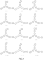
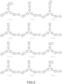
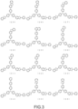
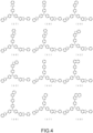
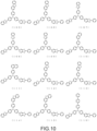
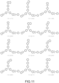
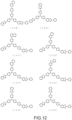
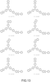
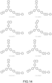
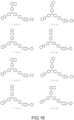
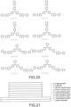
- Fig. 1 to Fig. 20 specific examples of favorable compounds among the amine compounds according to the present invention, which are suitable for use in the organic EL device, electronic apparatus, and electronic device according to the present invention, are shown in Fig. 1 to Fig. 20 , the present invention is not limited to these compounds.
- the purification of the amine compound according to the present invention is not particularly limited and may be performed by known methods used for purifying organic compounds, such as purification by column chromatography, adsorption purification with silica gel, activated carbon, activated clay, or the like, a recrystallization purification method with a solvent, a crystallization purification method, and a sublimation purification method, and the compound was identified by NMR analysis.
- the melting point, the glass transition temperature (Tg), and the refractive index were measured as physical property values.
- the melting point is an index of a vapor deposition property.
- the glass transition point (Tg) is an index of stability in a thin film state.
- the refractive index is an index regarding the improvement of light extraction efficiency.
- the melting point and the glass transition point (Tg) were measured with a powder using a high sensitivity differential scanning calorimeter (DSC3100SA manufactured by Bruker AXS GmbH).
- the refractive index and the extinction coefficient were measured by preparing a thin film having a thickness of 80 nm on a silicon substrate and using a spectrometer (F10-RT-UV manufactured by Filmetrics, INC.)
- the absorbance at wavelengths of 400 nm and 410 nm was calculated by adjusting the concentration to 10 -5 mol/L with a toluene solvent and using the compound according to the present invention, and the absorption coefficient was calculated by adjusting the concentration to four types of concentrations, i.e., 5.0 ⁇ 10 -6 mol/L, 1.0 ⁇ 10 -5 mol/L, 1.5 ⁇ 10 -5 mol/L, and 2.0 ⁇ 10 -5 mol/L, with a toluene solvent, from the calibration curve obtained by measurement using an ultraviolet-visible near-infrared spectrophotometer (V-650 manufactured by JASCO Corporation).
- V-650 ultraviolet-visible near-infrared spectrophotometer
- Examples of the structure of the organic EL device according to the present invention include, in the case of a light-emitting element having a top emission structure, those including an anode, a hole transport layer, a light-emitting layer, an electron transport layer, a cathode, and a capping layer in this order on a glass substrate, those including a hole injection layer between the anode and the hole transport layer, those including an electron blocking layer between the hole transport layer and the light-emitting layer, those including a hole blocking layer between the light-emitting layer and the electron transport layer, and those including an electron injection layer between the electron transport layer and the cathode.
- a light-emitting element having a top emission structure those including an anode, a hole transport layer, a light-emitting layer, an electron transport layer, a cathode, and a capping layer in this order on a glass substrate, those including a hole injection layer between the anode and the hole transport layer, those including an electron blocking layer between the
- an organic layer may serve as both the hole injection layer and the hole transport layer, both the hole transport layer and the electron blocking layer, both the hole blocking layer and the electron transport layer, or both the electron transport layer and the electron injection layer.
- two or more organic layers having the same function may be stacked.
- two hole transport layers may be stacked, two light-emitting layers may be stacked, two electron transport layers may be stacked, and two capping layers may be stacked.
- the total film thickness of the respective layers of the organic EL device is favorably approximately 200 nm to 750 nm, more favorably approximately 350 nm to 600 nm. Further, the film thickness of the capping layer is, for example, favorably 30 nm to 120 nm, more favorably 40 nm to 80 nm. In this case, favorable light extraction efficiency can be achieved. Note that the film thickness of the capping layer can be appropriately changed depending on the type of light-emitting material used in the light-emitting element, the thickness of the organic EL device other than the capping layer, and the like.
- an electrode material having a large work function such as ITO and gold, is used.
- an arylamine compound having three or more triphenylamine structures in the molecule linked by a single bond or a divalent group that does not contain a heteroatom such as a starburst triphenylamine derivative and various triphenylamine tetramers, a porphyrin compound typified by copper phthalocyanine, an acceptor heterocyclic compound such as hexacyanoazatriphenylene, and a coating type polymer material can be used. These may be deposited alone or may be mixed with other materials and deposited to form a single layer.
- a stacked structure of layers deposited alone, layers mixed and deposited, or layers including a layer deposited alone and a layer mixed and deposited may be provided. These materials can be formed into a thin film by a known method such as a spin coat method and an ink jet method in addition to a vapor deposition method.
- a benzidine derivative such as N,N'-diphenyl-N,N'-di(m-tolyl)benzidine (hereinafter, abbreviated as TPD), N,N'-diphenyl-N,N'-di( ⁇ -naphthyl)benzidine, and N,N,N',N'-tetrabiphenylylbenzidine, 1,1-bis[4-(di-4-tolylamino)phenyl]cyclohexane, particularly an arylamine compound having a structure in which two triphenylamine structures are linked by a single bond or a divalent group that does not contain a heteroatom in the molecule, such as N, N, N', N'-tetrabiphenylylbenzidine, or the like is favorably used.
- TPD N,N'-diphenyl-N,N'-di(m-tolyl)benzidine
- TPD N,N'-diphenyl-N,
- an arylamine compound having three or more triphenylamine structures in the molecule linked by a single bond or a divalent group that does not contain a heteroatom is favorably used.
- These may be deposited alone or may be mixed with other materials and deposited to form a single layer.
- a stacked structure of layers deposited alone, layers mixed and deposited, or layers including a layer deposited alone and a layer mixed and deposited may be provided.
- a coating type polymer material such as poly(3,4-ethylenedioxythiophene)/poly(styrene sulfonate) can be used. These materials can be formed into a thin film by a known method such as a spin coat method and an ink jet method in addition to a vapor deposition method.
- the hole injection layer or the hole transport layer those obtained by P-doping materials that are normally used in the layer with trisbromophenylaminehexachloroantimony, a radialene derivative (see, for example, Patent Literature 3), or the like, a polymer compound having a benzidine derivative structure such as TPD in its partial structure, or the like can be used.
- a compound having an electron blocking effect such as a carbazole derivative such as 4,4',4"-tri(N-carbazolyl)triphenylamine (hereinafter, abbreviated as TCTA), 9,9-bis[4-(carbazole-9-yl)phenyl]fluorene, 1,3-bis(carbazol-9-yl)benzene (hereinafter, abbreviated as mCP), and 2,2-bis(4-carbazol-9-yl-phenyl)adamantane and a compound having a triphenylsilyl group and a triarylamine structure typified by 9-[4-(carbazole-9-yl)phenyl]-9-[4-(triphenylsilyl)phenyl]-9H-fluorene can be used.
- TCTA 4,4',4"-tri(N-carbazolyl)triphenylamine
- mCP 1,3-bis(carbazol-9-yl)benzen
- These may be deposited alone or may be mixed with other materials and deposited to form a single layer. Further, a stacked structure of layers deposited alone, layers mixed and deposited, or layers including a layer deposited alone and a layer mixed and deposited may be provided. These materials can be formed into a thin film by a known method such as a spin coat method and an ink jet method in addition to a vapor deposition method.
- the light-emitting layer of the organic EL device for the light-emitting layer of the organic EL device according to the present invention, various metal complexes, an anthracene derivative, a bis-styrylbenzene derivative, a pyrene derivative, an oxazole derivative, a polyparaphenylene vinylene derivative, or the like can be used in addition to a metal complex of a quinolinol derivative including Alq 3 .
- the light-emitting layer may be formed of a host material and a dopant material, and an anthracene derivative is favorably used as the host material.
- a heterocyclic compound having an indole ring as a partial structure of a fused ring a heterocyclic compound having a carbazole ring as a partial structure of a fused ring, a carbazole derivative, a thiazole derivative, a benzimidazole derivative, a polydialkylfluorene derivative, or the like can be used.
- the dopant material quinacridone, coumarin, rubrene, perylene, and derivatives thereof, a benzopyran derivative, a rhodamine derivative, an aminostyryl derivative, and the like can be used. These may be deposited alone or may be mixed with other materials and deposited to form a single layer. A stacked structure of layers deposited alone, layers mixed and deposited, or layers including a layer deposited alone and a layer mixed and deposited may be provided.
- a phosphorescent emitter can be used as the light-emitting material.
- a phosphorescent emitter of a metal complex such as iridium and platinum can be used.
- a green phosphorescent emitter such as Ir(ppy) 3
- a blue phosphorescent emitter such as FIrpic and FIr6
- a red phosphorescent emitter such as Btp 2 Ir (acac)
- a carbazole derivative such as 4,4'-di(N-carbazolyl)biphenyl, TCTA, and mCP, which are hole injection/transport host materials, can be used.
- the electron transport host material p-bis(triphenylsilyl)benzene, 2,2',2''-(1,3,5-phenylene)-tris(1-phenyl-1H-benzimidazole), or the like can be used, and a high-performance organic EL device can be prepared.
- the phosphorescent light-emitting material In order to avoid concentration quenching, it is favorable to dope the phosphorescent light-emitting material with the host material by co-deposition in the range of 1 to 30 weight percent with respect to the entire light-emitting layer.
- a material that emits delayed fluorescence such as a CDCB derivative including PIC-TRZ, CC2TA, PXZ-TRZ, and 4CzIPN may be used (see, for example, Non-Patent Literature 7).
- a known method such as a spin coat method and an ink jet method in addition to a vapor deposition method.
- a compound having a hole blocking effect such as a phenanthroline derivative such as bathocuproine, a metal complex of a quinolinol derivative such as aluminum(III)bis(2-methyl-8-quinolinate)-4-phenylphenolate (hereinafter, abbreviated as BAlq), various rare earth complex, a triazole derivative, a triazine derivative, a pyrimidine derivative, an oxadiazole derivative, and a benzoazole derivative, can be used. These materials may also serve as the material of the electron transport layer. These may be deposited alone or may be mixed with other materials and deposited to form a single layer.
- a phenanthroline derivative such as bathocuproine
- a metal complex of a quinolinol derivative such as aluminum(III)bis(2-methyl-8-quinolinate)-4-phenylphenolate (hereinafter, abbreviated as BAlq)
- BAlq aluminum(III)bis(2-methyl-8-quinolinate)-4-
- a stacked structure of layers deposited alone, layers mixed and deposited, or layers including a layer deposited alone and a layer mixed and deposited may be provided. These materials can be formed into a thin film by a known method such as a spin coat method and an ink jet method in addition to a vapor deposition method.
- various metal complexes a triazole derivative, a triazine derivative, a pyrimidine derivative, an oxadiazole derivative, a pyridine derivative, a benzimidazole derivative, a benzoazole derivative, a thiadiazole derivative, an anthracene derivative, a carbodiimide derivative, a quinoxaline derivative, a pyridoindole derivative, a phenanthroline derivative, a silole derivative, and the like can be used in addition to the metal complex of a quinolinol derivative including Alq 3 and BAlq.
- These may be deposited alone or may be mixed with other materials and deposited to form a single layer. Further, a stacked structure of layers deposited alone, layers mixed and deposited, or layers including a layer deposited alone and a layer mixed and deposited may be provided. These materials can be formed into a thin film by a known method such as a spin coat method and an ink jet method in addition to a vapor deposition method.
- an alkali metal salt such as lithium fluoride and cesium fluoride, an alkaline earth metal salt such as magnesium fluoride, a metal complex of a quinolinol derivative such as lithium quinolinol, a metal oxide such as aluminum oxide, a metal such as ytterbium (Yb), samarium (Sm), calcium (Ca), strontium (Sr), and cesium (Cs), or the like can be used.
- Yb ytterbium
- Sm samarium
- Ca calcium
- Cs cesium
- those obtained by N-doping the material typically used for the respective layers with a metal such as cesium can be used.
- an electrode material having a low work function such as aluminum
- an alloy having a lower work function such as a magnesium silver alloy, a magnesium calcium alloy, a magnesium indium alloy, and an aluminum magnesium alloy, ITO, IZO, or the like is used as an electrode material.
- an amine compound represented by the general formula(A), (B), or (C) is used for the capping layer of the organic EL device according to the present invention. These may be deposited alone or may be mixed with other materials and deposited to form a single layer. A stacked structure of layers deposited alone, layers mixed and deposited, or layers including a layer deposited alone and a layer mixed and deposited may be provided. These materials can be formed into a thin film by a known method such as a spin coat method and an ink jet method in addition to a vapor deposition method.
- the present invention is not limited thereto and is applicable similarly to an organic EL device having a bottom emission structure and an organic EL device having a dual emission structure in which light is emitted from the upper part and the bottom portion.
- the electrode present in the direction in which light is extracted from the light-emitting element to the outside needs to be transparent or semi-transparent.
- the refractive index of the material for forming a capping layer is favorably larger than the refractive index of the adjacent electrode. That is, the capping layer improves the light extraction efficiency of the organic EL device, but this effect is effective when the reflectance at the interface between the capping layer and the material in contact with the capping layer is greater, because the effect of the optical interference is larger. For this reason, the refractive index of the material for forming a capping layer is favorably larger than the refractive index of the adjacent electrode.
- the refractive index in the wavelength range of 450 nm to 750 nm of light transmitted through the capping layer only needs to be 1.70 or more, and is more favorably 1.80 or more, particularly favorably 1.85 or more, and still more favorably 1.90 or more.
- the thickness of the capping layer is favorably in the range from 30 nm to 120 nm, more favorably 40 nm to 80 nm.
- the capping layer of the organic EL device according to the present invention has an extinction coefficient of 0.2 or more in a wavelength range from 400 nm to 410 and absorbance in an absorption spectrum at a concentration of 10 -5 mol/L of 0.2 or more in the wavelength range from 400 nm to 410 nm.
- the capping layer may be prepared by forming a stacked layer or a mixed layer of two or more types of different constituent materials. Note that at least one of the constituent materials is the amine compound according to the present invention. It is favorable that the refractive index, the extinction coefficient, and the absorbance of the capping layer are within the above numerical ranges.
- N-(4-benzofuran-2-yl-phenyl)-N-(4-dibenzofuran-3-yl-phenyl)-amine 10.0 g, 6-(4-chloro-phenyl)-2-phenyl-benzooxazole: 7.4 g, tris(dibenzylideneacetone)dipalladium(0): 0.4 g, tri-t-butylphosphine: 0.2 g, and t-butoxy sodium: 3.2 g were placed in a reaction vessel purged with nitrogen and refluxed and stirred overnight in xylene solvent. After the mixture is allowed to cool, methanol was added to the system and the precipitated solid was filtered to obtain a crude product.
- N-(4-benzooxazole-2-yl-phenyl)-N-(4-benzothiazole-2-yl-phenyl)-amine 7.0 g
- 6-(4-chloro-phenyl)-2-naphthalene-2-yl-benzooxazole 6.5 g
- tris(dibenzylideneacetone)dipalladium(0) 0.3 g
- tri-t-butylphosphine 0.1 g
- t-butoxy sodium 2.4 g were placed in a reaction vessel purged with nitrogen and refluxed and stirred overnight in xylene solvent.
- N-(4-benzofuran-2-yl-phenyl)-N-(4-benzooxazole-2-yl-phenyl)-amine 6.4 g, 6-(4-chloro-phenyl)-2-naphthalene-2-yl-benzooxazole: 6.2 g, tris(dibenzylideneacetone)dipalladium(0): 0.3 g, tri-t-butylphosphine: 0.1 g, and t-butoxy sodium: 2.3 g were placed in a reaction vessel purged with nitrogen and refluxed and stirred overnight in xylene solvent.
- ⁇ (ppm) 8.81(1H), 8.34(1H), 8.16(2H), 8.01(1H), 7.99(1H), 7.91(1H), 7.84(4H), 7.75(1H), 7.64(3H), 7.58(4H), 7.52(1H), 7.32-7.26(9H), 7.24(1H), and 6.98(1H).
- N-(4-benzooxazole-2-yl-phenyl)-N-(4-naphthalene-2-yl-phenyl)-amine 5.8 g, 6-(4-chloro-phenyl)-2-phenyl-benzooxazole: 4.7 g, tris(dibenzylideneacetone)dipalladium(0): 0.3 g, tri-t-butylphosphine: 0.1 g, and t-butoxy sodium: 2.7 g were placed in a reaction vessel purged with nitrogen and refluxed and stirred overnight in toluene solvent. After the mixture is allowed to cool, methanol was added to the system and the precipitated solid was filtered to obtain a crude product.
- ⁇ (ppm) 8.32(2H), 8.18(2H), 8.09(1H), 7.94(2H), 7.90(1H), 7.86(1H), 7.84(1H), 7.80(1H), 7.78(1H), 7.75(2H), 7.66(3H), 7.62-7.48(6H), 7.40-7.33(6H), and 7.31(2H).
- N,N-bis(4-benzooxazole-2-yl-phenyl)-amine 7.1 g, 6-(4-chloro-phenyl)-2-phenyl-benzooxazole: 5.9 g, tris(dibenzylideneacetone)dipalladium(0): 0.3 g, tri-t-butylphosphine: 0.2 g, and t-butoxy sodium: 3.4 g were placed in a reaction vessel purged with nitrogen and refluxed and stirred overnight in toluene solvent. After the mixture is allowed to cool, methanol was added to the system and the precipitated solid was filtered to obtain a crude product.
- N-(4-benzothiophene-2-yl-phenyl)-N- ⁇ 4-(2-phenyl-benzooxazole-6-yl)-phenyl ⁇ -amine 6.1 g
- 2-(4-bromophenyl)-benzothiazole 3.9 g
- tris(dibenzylideneacetone)dipalladium(0) 0.2 g
- tri-t-butylphosphine 0.1 g
- t-butoxy sodium 1.8 g were placed in a reaction vessel purged with nitrogen and refluxed and stirred overnight in xylene solvent. After the mixture is allowed to cool, methanol was added to the system and the precipitated solid was filtered to obtain a crude product.
- ⁇ (ppm) 8.31(2H), 8.08(1H), 8.03(2H), 7.91(1H), 7.85(2H), 7.83(1H), 7.80(1H), 7.70(2H), 7.65(3H), 7.58 (3H), 7.54(1H), 7.51(1H), 7.43-7.30(5H), and 7.28(4H).
- N-(4-benzooxazole-2-yl-phenyl)-N-(4-naphthalene-2-yl-phenyl)-amine 10.0 g
- 6-(4-chloro-phenyl)-2-phenyl-benzooxazole 7.9 g
- tris(dibenzylideneacetone)dipalladium(0) 0.4 g
- tri-t-butylphosphine 0.2 g
- t-butoxy sodium 4.5 g were placed in a reaction vessel purged with nitrogen and refluxed and stirred overnight in toluene solvent. After the mixture is allowed to cool, methanol was added to the system and the precipitated solid was filtered to obtain a crude product.
- ⁇ (ppm) 8.55(1H), 8.26(1H), 8.09(1H), 7.94(2H), 7.90(1H), 7.85(2H), 7.80(3H), 7.72(2H), 7.68(4H), 7.63(2H), 7.52(3H), 7.41(2H), 7.37 (1H), 7.34(5H), and 7.27(2H).
- N-(4-benzothiophene-2-yl-phenyl)-N- ⁇ 4-(2-phenyl-benzooxazole-6-yl)-phenyl ⁇ -amine 12.6 g
- 2-(4-bromophenyl)-[1,10]phenanthroline 16.7 g
- tris(dibenzylideneacetone)dipalladium(0) 0.9 g
- tri-t-butylphosphine 0.4 g
- t-butoxy sodium 9.5 g were placed in a reaction vessel purged with nitrogen and refluxed and stirred overnight in toluene solvent.
- ⁇ (ppm) 9.26(1H), 8.35-8.26(6H), 8.10(1H), 7.85(4H), 7.79(2H), 7.71-7.61(6H), 7.57(3H), 7.53(1H), 7.37(3H), 7.33(3H), and 7.28(2H).
- N,N-bis(4-benzothiophene-2-yl-phenyl)-amine 7.6 g, 6-(4-chloro-phenyl)-2-phenyl-benzooxazole: 5.9 g, tris(dibenzylideneacetone)dipalladium(0): 0.3 g, tri-t-butylphosphine: 0.2 g, and t-butoxy sodium: 3.4 g were placed in a reaction vessel purged with nitrogen and refluxed and stirred overnight in toluene solvent. After the mixture is allowed to cool, methanol was added to the system and the precipitated solid was filtered to obtain a crude product.
- ⁇ (ppm) 8.31(2H), 7.85(3H), 7.82(1H), 7.79(2H), 7.68(4H), 7.65-7.60(3H), 7.60-7.55(3H), 7.52(2H), 7.35(4H), 7.30(2H), and 7.25(4H).
- N-(4-benzooxazole-2-yl-phenyl)-N-(4-benzothiophene-2-yl-phenyl)-amine 10.0 g
- 6-(4-chlorophenyl)-2-naphthalene-2-yl-benzooxazole 9.4 g
- tris(dibenzylideneacetone)dipalladium(0) 0.4 g
- tri-t-butylphosphine 0.2 g
- t-butoxy sodium 3.4 g were placed in a reaction vessel purged with nitrogen and refluxed and stirred overnight in xylene solvent.
- N-(4-benzofuran-2-yl-phenyl)-N-(4-benzothiophene-2-yl-phenyl)-amine 10.0 g
- 6-(4-chloro-phenyl)-2-naphthalene-2-yl-benzooxazole 9.4 g
- tris(dibenzylideneacetone)dipalladium(0) 0.4 g
- tri-t-butylphosphine 0.2 g
- t-butoxy sodium 3.5 g were placed in a reaction vessel purged with nitrogen and refluxed and stirred overnight in xylene solvent.
- N-(4-benzofuran-2-yl-phenyl)-N-(4-benzooxazole-2-yl-phenyl)-amine 9.8 g
- 6-(4-chloro-phenyl)-2-phenyl-benzothiazole 8.6 g
- tris(dibenzylideneacetone)dipalladium(0) 0.5 g
- tri-t-butylphosphine 0.2 g
- t-butoxy sodium 3.5 g
- N-(4-benzofuran-2-yl-phenyl)-N-(4-benzooxazole-2-yl-phenyl)-amine 10.0 g
- 6-(4'-bromo-[1,1']biphenyl-4-yl)-2-phenyl-benzooxazole 11.7 g
- tris(dibenzylideneacetone)dipalladium(0) 0.5 g
- tri-t-butylphosphine 0.2 g
- t-butoxy sodium 3.6 g were placed in a reaction vessel purged with nitrogen and refluxed and stirred overnight in toluene solvent.
- N-(4-benzooxazole-2-yl-phenyl)-N-(4-benzothiophene-2-yl-phenyl)-amine 10.0 g
- 6-(4'-bromo-[1,1']biphenyl-4-yl)-2-phenyl-benzooxazole 11.2 g
- tris(dibenzylideneacetone)dipalladium(0) 0.4 g
- tri-t-butylphosphine 0.2 g
- t-butoxy sodium 3.4 g were placed in a reaction vessel purged with nitrogen and refluxed and stirred overnight in toluene solvent.
- N-phenyl-N- ⁇ 4'-(2-phenyl-benzooxazole-6-yl)-[1,1']biphenyl-4-yl ⁇ -amine 12.0 g
- 2-(4-bromo-phenyl)-benzooxazole 8.3 g
- tris(dibenzylideneacetone)dipalladium(0) 0.5 g
- tri-t-butylphosphine 0.2 g
- t-butoxy sodium 5.3 g were placed in a reaction vessel purged with nitrogen and refluxed and stirred overnight in toluene solvent. After the mixture is allowed to cool, methanol was added to the system and the precipitated solid was filtered to obtain a crude product.
- N-phenyl-N- ⁇ 4'-(2-naphthalene-2-yl-benzooxazole-6-yl)-[1,1']biphenyl-4-yl ⁇ -amine 11.0 g
- 2-(4-bromophenyl)-benzooxazole 6.8 g
- tris(dibenzylideneacetone)dipalladium(0) 0.4 g
- tri-t-butylphosphine 0.2 g
- t-butoxy sodium 4.3 g were placed in a reaction vessel purged with nitrogen and refluxed and stirred overnight in toluene solvent.
- ⁇ (ppm) 8.83(1H), 8.37 (1H), 8.14(2H), 8.04(1H), 8.02(1H), 7.94(1H), 7.90(1H), 7.89(1H), 7.80-7.72(5H), 7.70(1H), 7.67-7.55(5H), 7.43-7.31(4H), 7.31-7.25(4H), 7.23(2H), and 7.20(1H).
- N-phenyl-N- ⁇ 4'-(2-phenyl-benzooxazole-6-yl)-[1,1']biphenyl-4-yl ⁇ -amine 10.0 g
- 2-(4'-chloro-[1,1']biphenyl-4-yl)-benzooxazole 7.7 g
- tris(dibenzylideneacetone)dipalladium(0) 0.4 g
- tri-t-butylphosphine 0.2 g
- t-butoxy sodium 4.4 g were placed in a reaction vessel purged with nitrogen and refluxed and stirred overnight in toluene solvent.
- N-phenyl-N- ⁇ 4-(2-phenyl-benzooxazole-6-yl)-phenyl ⁇ -amine 6.5 g
- 2-(4'-chloro-[1,1']biphenyl-4-yl)-benzooxazole 6.0 g
- tris(dibenzylideneacetone)dipalladium(0) 0.3 g
- tri-t-butylphosphine 0.2 g
- t-butoxy sodium 3.4 g were placed in a reaction vessel purged with nitrogen and refluxed and stirred overnight in xylene solvent. After the mixture is allowed to cool, methanol was added to the system and the precipitated solid was filtered to obtain a crude product.
- N-phenyl-N- ⁇ 4-(2-phenyl-benzooxazole-6-yl)-phenyl ⁇ -amine 6.5 g
- 2-(4'-chloro-[1,1']biphenyl-4-yl)-benzofuran 6.0 g
- tris(dibenzylideneacetone)dipalladium(0) 0.3 g
- tri-t-butylphosphine 0.2 g
- t-butoxy sodium 3.4 g were placed in a reaction vessel purged with nitrogen and refluxed and stirred overnight in xylene solvent. After the mixture is allowed to cool, methanol was added to the system and the precipitated solid was filtered to obtain a crude product.
- N-phenyl-N- ⁇ 4-(2-naphthalene-2-yl-benzooxazole-6-yl)-phenyl ⁇ -amine 6.3 g
- 2-(4'-chloro-[1,1']biphenyl-4-yl)-benzooxazole 5.1 g
- tris(dibenzylideneacetone)dipalladium(0) 0.3 g
- tri-t-butylphosphine 0.1 g
- t-butoxy sodium 2.9 g were placed in a reaction vessel purged with nitrogen and refluxed and stirred overnight in xylene solvent.
- N-(4-benzofuran-2-yl-phenyl)-N-(4-benzooxazole-2-yl-phenyl)-amine 8.0 g, 6-(4-chloro-phenyl)-2-(furan-2-yl)-benzooxazole: 6.5 g, tris(dibenzylideneacetone)dipalladium(0): 0.4 g, tri-t-butylphosphine: 0.2 g, and t-butoxy sodium: 2.9 g were placed in a reaction vessel purged with nitrogen and refluxed and stirred overnight in xylene solvent. After the mixture is allowed to cool, the filtrate obtained by filtration was concentrated to obtain a crude product.
- N-(4-benzofuran-2-yl-phenyl)-N-(4-benzothiophene-2-yl-phenyl)-amine 7.2 g
- 6-(4-chloro-phenyl)-2-(furan-2-yl)-benzooxazole 5.6 g
- tris(dibenzylideneacetone)dipalladium(0) 0.3 g
- tri-t-butylphosphine 0.1 g
- t-butoxy sodium 2.5 g were placed in a reaction vessel purged with nitrogen and refluxed and stirred overnight in xylene solvent. After the mixture is allowed to cool, methanol was added to the system and the precipitated solid was filtered to obtain a crude product.
- N-(4-benzofuran-2-yl-phenyl)-N-(4-benzooxazole-2-yl-phenyl)-amine 9.0 g, 6-(4-chloro-phenyl)-2-(thiophene-2-yl)-benzooxazole: 7.7 g, tris(dibenzylideneacetone)dipalladium(0): 0.4 g, tri-t-butylphosphine: 0.2 g, and t-butoxy sodium: 3.2 g were placed in a reaction vessel purged with nitrogen and refluxed and stirred overnight in xylene solvent. After the mixture is allowed to cool, the filtrate obtained by filtration was concentrated to obtain a crude product.
- N-(4-benzofuran-2-yl-phenyl)-N-(4-benzothiophene-2-yl-phenyl)-amine 7.2 g, 6-(4-chloro-phenyl)-2-(furan-2-yl)-benzooxazole: 5.9 g, tris(dibenzylideneacetone)dipalladium(0): 0.3 g, tri-t-butylphosphine: 0.1 g, and t-butoxy sodium: 2.5 g were placed in a reaction vessel purged with nitrogen and refluxed and stirred overnight in xylene solvent. After the mixture is allowed to cool, methanol was added to the system and the precipitated solid was filtered to obtain a crude product.
- N-(4-naphthalene-2-yl-phenyl)-N-(2-phenyl-benzooxazole-6-yl)-amine 6.2 g, 6-(4-chloro-phenyl)-2-phenyl-benzooxazole: 5.1 g, tris(dibenzylideneacetone)dipalladium(0): 0.3 g, tri-t-butylphosphine: 0.1 g, and t-butoxy sodium: 2.9 g were placed in a reaction vessel purged with nitrogen and refluxed and stirred overnight in toluene solvent. After the mixture is allowed to cool, methanol was added to the system and the precipitated solid was filtered to obtain a crude product.
- N-(4-dibenzofuran-3-yl-phenyl)-N-(2-phenyl-benzooxazole-6-yl)-amine 8.8 g, 6-(4-chloro-phenyl)-2-phenyl-benzooxazole: 6.5 g, tris(dibenzylideneacetone)dipalladium(0): 0.4 g, tri-t-butylphosphine: 0.2 g, and t-butoxy sodium: 3.7 g were placed in a reaction vessel purged with nitrogen and refluxed and stirred overnight in toluene solvent. After the mixture is allowed to cool, methanol was added to the system and the precipitated solid was filtered to obtain a crude product.
- N,N-bis ⁇ 4-(2-phenyl-benzooxazole-6-yl)-phenyl ⁇ -amine 7.0 g, 3-bromo-dibenzofuran: 3.4 g, tris(dibenzylideneacetone)dipalladium(0): 0.2 g, tri-t-butylphosphine: 0.1 g, and t-butoxy sodium: 2.4 g were placed in a reaction vessel purged with nitrogen and refluxed and stirred overnight in toluene solvent. After the mixture is allowed to cool, methanol was added to the system and the precipitated solid was filtered to obtain a crude product.
- 2-amino-dibenzothiophene 4.5 g, 6-(4-chlorophenyl)-2-phenyl-benzooxazole: 15.2 g, tris(dibenzylideneacetone)dipalladium(0): 0.8 g, tri-t-butylphosphine: 0.4 g, and t-butoxy sodium: 6.5 g were placed in a reaction vessel purged with nitrogen and refluxed and stirred overnight in toluene solvent. After the mixture is allowed to cool, methanol was added to the system and the precipitated solid was filtered to obtain a crude product.
- ⁇ (ppm) 8.31(4H), 8.06(1H), 8.05(1H), 7.89(1H), 7.86-7.81(5H), 7.65(2H), 7.62(4H), 7.59-7.53(6H), 7.48(1H), 7.43(1H), 7.40(1H), and 7.32(4H).
- 4-benzooxazole-2-yl-aniline 4.0 g, 6-(4-chlorophenyl)-2-phenyl-benzooxazole: 12.8 g, tris(dibenzylideneacetone)dipalladium(0): 0.7 g, tri-t-butylphosphine: 0.3 g, and t-butoxy sodium: 5.5 g were placed in a reaction vessel purged with nitrogen and refluxed and stirred overnight in toluene solvent. After the mixture is allowed to cool, methanol was added to the system and the precipitated solid was filtered to obtain a crude product.
- N-phenyl-N- ⁇ 4'-(2-phenyl-benzooxazole-6-yl)-[1,1']biphenyl-4-yl ⁇ -amine 6.4 g, 6-(4-chloro-phenyl)-2-phenyl-benzooxazole: 4.9 g, tris(dibenzylideneacetone)dipalladium(0): 0.3 g, tri-t-butylphosphine: 0.1 g, and t-butoxy sodium: 2.8 g were placed in a reaction vessel purged with nitrogen and refluxed and stirred overnight in toluene solvent.
- the above measurement results show that the amine compound according to the present invention has a glass transition temperature of 100°C or more and is stable in a thin-film state.
- a deposition film having a film thickness of 80 nm was prepared on a silicon substrate using each of the compounds obtained in the Examples, and refractive indices n at wavelengths of 450 nm and 750 nm and extinction coefficients k at wavelengths of 400 nm and 410 nm were measured using a spectrometer (F10-RT-UV manufactured by Filmetrics, INC.).
- a spectrometer F10-RT-UV manufactured by Filmetrics, INC.
- measurement was also made on a comparative compound (2-1) and a comparative compound (2-2) having the following structural formulae and Alq 3 (see, for example, Patent Literature 4 and Patent Literature 5).
- the measurement results of the refractive index n and the extinction coefficient k are collectively shown in Table 2.
- Example 1 Compound 40 2.36 1.93 0.86 0.56
- Example 2 Compound 50 2.37 1.91 0.98 0.70
- Example 3 Compound 69 2.50 1.95 1.11 0.94
- Example 4 Compound 70 2.45 1.94 1.05 0.78
- Example 5 Compound 78 2.43 1.95 1.02 0.77
- Example 6 Compound 119 2.43 1.93 1.06 0.82
- Example 7 Compound 150 2.38 1.92 1.00 0.70
- Example 8 Compound 2 2.34 1.90 0.92 0.61
- Example 9 Compound 17 2.34 1.90 0.94 0.65
- Example 10 Compound 38 2.53 1.93 1.18 1.02
- Example 11 Compound 52 2.35 1.92 0.64 0.36
- Example 12 Compound 61 2.50 1.95 1.01 0.91
- Example 13 Compound 62 2.40 1.94 0.98 0.72
- Example 14 Compound 71 2.46 1.95 1.06 0.81
- the compound according to the present invention has a refractive index equal to or greater than those of Alq 3 , the comparative compound (2-1), and the comparative compound (2-2) in the wavelength range of 450 nm to 750 nm, and has low extinction coefficients at the wavelengths of 400 nm and 410 nm, so that there is little loss of light absorbed in the blue region. This is expected to improve the light extraction efficiency in the organic EL device in which the amine compound according to the present invention is used as the constituent material of the capping layer.
- the organic EL device was prepared by depositing a hole injection layer 3, a hole transport layer 4, a light-emitting layer 5, an electron transport layer 6, an electron injection layer 7, a cathode 8, and a capping layer 9 in this order on a reflective ITO electrode formed in advance as a transparent anode 2 on a glass substrate 1.
- the glass substrate 1 on which ITO having a film thickness of 50 nm, a reflective film formed of a silver alloy having a film thickness of 100 nm, and ITO having a film thickness of 5 nm were deposited in this order was subjected to ultrasonic cleaning in isopropyl alcohol for 20 minutes and then dried on a hot plate heated to 250°C for 10 minutes. After that, UV ozone treatment was performed for 2 minutes, this glass substrate with ITO was attached in a vacuum deposition machine, and the pressure was reduced to 0.001 Pa or less.
- the hole transport layer 4 was formed using the compound (3-1) having the following structural formula on this hole injection layer 3 to have a film thickness of 140 nm.
- the electron injection layer 7 was formed using lithium fluoride on this electron transport layer 6 to have a film thickness of 1 nm.
- the cathode 8 was formed using a magnesium silver alloy on this electron injection layer 7 to have a film thickness of 12 nm.
- the capping layer 9 was formed using the compound (40) according to Example 1 to have a film thickness of 60 nm. The properties of the prepared organic EL device were measured in the atmosphere at room temperature.
- An organic EL device was prepared under the same conditions as in Example 44 except that the compound (50) according to Example 2 was formed as the capping layer 9 to have a film thickness of 60 nm instead of the compound (40) according to Example 1.
- the properties of the prepared organic EL device were measured in the atmosphere at room temperature.
- the measurement results of the light emission properties 10 when a direct current voltage was applied to the prepared organic EL device are collectively shown in Table 3.
- An organic EL device was prepared under the same conditions as in Example 44 except that the compound (69) according to Example 3 was formed as the capping layer 9 to have a film thickness of 60 nm instead of the compound (40) according to Example 1.
- the properties of the prepared organic EL device were measured in the atmosphere at room temperature. The measurement results of the light emission properties when a direct current voltage was applied to the prepared organic EL device are collectively shown in Table 3.
- An organic EL device was prepared under the same conditions as in Example 44 except that the compound (70) according to Example 4 was formed as the capping layer 9 to have a film thickness of 60 nm instead of the compound (40) according to Example 1.
- the properties of the prepared organic EL device were measured in the atmosphere at room temperature. The measurement results of the light emission properties when a direct current voltage was applied to the prepared organic EL device are collectively shown in Table 3.
- An organic EL device was prepared under the same conditions as in Example 44 except that the compound (78) according to Example 5 was formed as the capping layer 9 to have a film thickness of 60 nm instead of the compound (40) according to Example 1.
- the properties of the prepared organic EL device were measured in the atmosphere at room temperature. The measurement results of the light emission properties when a direct current voltage was applied to the prepared organic EL device are collectively shown in Table 3.
- An organic EL device was prepared under the same conditions as in Example 44 except that the compound (119) according to Example 6 was formed as the capping layer 9 to have a film thickness of 60 nm instead of the compound (40) according to Example 1.
- the properties of the prepared organic EL device were measured in the atmosphere at room temperature. The measurement results of the light emission properties when a direct current voltage was applied to the prepared organic EL device are collectively shown in Table 3.
- An organic EL device was prepared under the same conditions as in Example 44 except that the compound (150) according to Example 7 was formed as the capping layer 9 to have a film thickness of 60 nm instead of the compound (40) according to Example 1.
- the properties of the prepared organic EL device were measured in the atmosphere at room temperature. The measurement results of the light emission properties when a direct current voltage was applied to the prepared organic EL device are collectively shown in Table 3.
- An organic EL device was prepared under the same conditions as in Example 44 except that the compound (2) according to Example 8 was formed as the capping layer 9 to have a film thickness of 60 nm instead of the compound (40) according to Example 1.
- the properties of the prepared organic EL device were measured in the atmosphere at room temperature. The measurement results of the light emission properties when a direct current voltage was applied to the prepared organic EL device are collectively shown in Table 3.
- An organic EL device was prepared under the same conditions as in Example 44 except that the compound (17) according to Example 9 was formed as the capping layer 9 to have a film thickness of 60 nm instead of the compound (40) according to Example 1.
- the properties of the prepared organic EL device were measured in the atmosphere at room temperature. The measurement results of the light emission properties when a direct current voltage was applied to the prepared organic EL device are collectively shown in Table 3.
- An organic EL device was prepared under the same conditions as in Example 44 except that the compound (38) according to Example 10 was formed as the capping layer 9 to have a film thickness of 60 nm instead of the compound (40) according to Example 1.
- the properties of the prepared organic EL device were measured in the atmosphere at room temperature. The measurement results of the light emission properties when a direct current voltage was applied to the prepared organic EL device are collectively shown in Table 3.
- An organic EL device was prepared under the same conditions as in Example 44 except that the compound (52) according to Example 11 was formed as the capping layer 9 to have a film thickness of 60 nm instead of the compound (40) according to Example 1.
- the properties of the prepared organic EL device were measured in the atmosphere at room temperature. The measurement results of the light emission properties when a direct current voltage was applied to the prepared organic EL device are collectively shown in Table 3.
- An organic EL device was prepared under the same conditions as in Example 44 except that the compound (61) according to Example 12 was formed as the capping layer 9 to have a film thickness of 60 nm instead of the compound (40) according to Example 1.
- the properties of the prepared organic EL device were measured in the atmosphere at room temperature. The measurement results of the light emission properties when a direct current voltage was applied to the prepared organic EL device are collectively shown in Table 3.
- An organic EL device was prepared under the same conditions as in Example 44 except that the compound (62) according to Example 13 was formed as the capping layer 9 to have a film thickness of 60 nm instead of the compound (40) according to Example 1.
- the properties of the prepared organic EL device were measured in the atmosphere at room temperature. The measurement results of the light emission properties when a direct current voltage was applied to the prepared organic EL device are collectively shown in Table 3.
- An organic EL device was prepared under the same conditions as in Example 44 except that the compound (71) according to Example 14 was formed as the capping layer 9 to have a film thickness of 60 nm instead of the compound (40) according to Example 1.
- the properties of the prepared organic EL device were measured in the atmosphere at room temperature. The measurement results of the light emission properties when a direct current voltage was applied to the prepared organic EL device are collectively shown in Table 3.
- An organic EL device was prepared under the same conditions as in Example 44 except that the compound (79) according to Example 15 was formed as the capping layer 9 to have a film thickness of 60 nm instead of the compound (40) according to Example 1.
- the properties of the prepared organic EL device were measured in the atmosphere at room temperature. The measurement results of the light emission properties when a direct current voltage was applied to the prepared organic EL device are collectively shown in Table 3.
- An organic EL device was prepared under the same conditions as in Example 44 except that the compound (101) according to Example 16 was formed as the capping layer 9 to have a film thickness of 60 nm instead of the compound (40) according to Example 1.
- the properties of the prepared organic EL device were measured in the atmosphere at room temperature. The measurement results of the light emission properties when a direct current voltage was applied to the prepared organic EL device are collectively shown in Table 3.
- An organic EL device was prepared under the same conditions as in Example 44 except that the compound (137) according to Example 17 was formed as the capping layer 9 to have a film thickness of 60 nm instead of the compound (40) according to Example 1.
- the properties of the prepared organic EL device were measured in the atmosphere at room temperature. The measurement results of the light emission properties when a direct current voltage was applied to the prepared organic EL device are collectively shown in Table 3.
- An organic EL device was prepared under the same conditions as in Example 44 except that the compound (138) according to Example 18 was formed as the capping layer 9 to have a film thickness of 60 nm instead of the compound (40) according to Example 1.
- the properties of the prepared organic EL device were measured in the atmosphere at room temperature. The measurement results of the light emission properties when a direct current voltage was applied to the prepared organic EL device are collectively shown in Table 3.
- An organic EL device was prepared under the same conditions as in Example 44 except that the compound (155) according to Example 19 was formed as the capping layer 9 to have a film thickness of 60 nm instead of the compound (40) according to Example 1.
- the properties of the prepared organic EL device were measured in the atmosphere at room temperature. The measurement results of the light emission properties when a direct current voltage was applied to the prepared organic EL device are collectively shown in Table 3.
- An organic EL device was prepared under the same conditions as in Example 44 except that the compound (171) according to Example 20 was formed as the capping layer 9 to have a film thickness of 60 nm instead of the compound (40) according to Example 1.
- the properties of the prepared organic EL device were measured in the atmosphere at room temperature. The measurement results of the light emission properties when a direct current voltage was applied to the prepared organic EL device are collectively shown in Table 3.
- An organic EL device was prepared under the same conditions as in Example 44 except that the compound (173) according to Example 21 was formed as the capping layer 9 to have a film thickness of 60 nm instead of the compound (40) according to Example 1.
- the properties of the prepared organic EL device were measured in the atmosphere at room temperature. The measurement results of the light emission properties when a direct current voltage was applied to the prepared organic EL device are collectively shown in Table 3.
- An organic EL device was prepared under the same conditions as in Example 44 except that the compound (177) according to Example 22 was formed as the capping layer 9 to have a film thickness of 60 nm instead of the compound (40) according to Example 1.
- the properties of the prepared organic EL device were measured in the atmosphere at room temperature. The measurement results of the light emission properties when a direct current voltage was applied to the prepared organic EL device are collectively shown in Table 3.
- An organic EL device was prepared under the same conditions as in Example 44 except that the compound (180) according to Example 23 was formed as the capping layer 9 to have a film thickness of 60 nm instead of the compound (40) according to Example 1.
- the properties of the prepared organic EL device were measured in the atmosphere at room temperature. The measurement results of the light emission properties when a direct current voltage was applied to the prepared organic EL device are collectively shown in Table 3.
- An organic EL device was prepared under the same conditions as in Example 44 except that the compound (182) according to Example 24 was formed as the capping layer 9 to have a film thickness of 60 nm instead of the compound (40) according to Example 1.
- the properties of the prepared organic EL device were measured in the atmosphere at room temperature. The measurement results of the light emission properties when a direct current voltage was applied to the prepared organic EL device are collectively shown in Table 3.
- An organic EL device was prepared under the same conditions as in Example 44 except that the compound (184) according to Example 25 was formed as the capping layer 9 to have a film thickness of 60 nm instead of the compound (40) according to Example 1.
- the properties of the prepared organic EL device were measured in the atmosphere at room temperature. The measurement results of the light emission properties when a direct current voltage was applied to the prepared organic EL device are collectively shown in Table 3.
- An organic EL device was prepared under the same conditions as in Example 44 except that the compound (188) according to Example 26 was formed as the capping layer 9 to have a film thickness of 60 nm instead of the compound (40) according to Example 1.
- the properties of the prepared organic EL device were measured in the atmosphere at room temperature. The measurement results of the light emission properties when a direct current voltage was applied to the prepared organic EL device are collectively shown in Table 3.
- An organic EL device was prepared under the same conditions as in Example 44 except that the compound (189) according to Example 27 was formed as the capping layer 9 to have a film thickness of 60 nm instead of the compound (40) according to Example 1.
- the properties of the prepared organic EL device were measured in the atmosphere at room temperature. The measurement results of the light emission properties when a direct current voltage was applied to the prepared organic EL device are collectively shown in Table 3.
- An organic EL device was prepared under the same conditions as in Example 44 except that the compound (190) according to Example 28 was formed as the capping layer 9 to have a film thickness of 60 nm instead of the compound (40) according to Example 1.
- the properties of the prepared organic EL device were measured in the atmosphere at room temperature. The measurement results of the light emission properties when a direct current voltage was applied to the prepared organic EL device are collectively shown in Table 3.
- An organic EL device was prepared under the same conditions as in Example 44 except that the compound (191) according to Example 29 was formed as the capping layer 9 to have a film thickness of 60 nm instead of the compound (40) according to Example 1.
- the properties of the prepared organic EL device were measured in the atmosphere at room temperature. The measurement results of the light emission properties when a direct current voltage was applied to the prepared organic EL device are collectively shown in Table 3.
- An organic EL device was prepared under the same conditions as in Example 44 except that the compound (192) according to Example 30 was formed as the capping layer 9 to have a film thickness of 60 nm instead of the compound (40) according to Example 1.
- the properties of the prepared organic EL device were measured in the atmosphere at room temperature. The measurement results of the light emission properties when a direct current voltage was applied to the prepared organic EL device are collectively shown in Table 3.
- An organic EL device was prepared under the same conditions as in Example 44 except that the compound (193) according to Example 31 was formed as the capping layer 9 to have a film thickness of 60 nm instead of the compound (40) according to Example 1.
- the properties of the prepared organic EL device were measured in the atmosphere at room temperature. The measurement results of the light emission properties when a direct current voltage was applied to the prepared organic EL device are collectively shown in Table 3.
- An organic EL device was prepared under the same conditions as in Example 44 except that the compound (195) according to Example 32 was formed as the capping layer 9 to have a film thickness of 60 nm instead of the compound (40) according to Example 1.
- the properties of the prepared organic EL device were measured in the atmosphere at room temperature. The measurement results of the light emission properties when a direct current voltage was applied to the prepared organic EL device are collectively shown in Table 3.
- An organic EL device was prepared under the same conditions as in Example 44 except that the compound (196) according to Example 33 was formed as the capping layer 9 to have a film thickness of 60 nm instead of the compound (40) according to Example 1.
- the properties of the prepared organic EL device were measured in the atmosphere at room temperature. The measurement results of the light emission properties when a direct current voltage was applied to the prepared organic EL device are collectively shown in Table 3.
- An organic EL device was prepared under the same conditions as in Example 44 except that the compound (198) according to Example 34 was formed as the capping layer 9 to have a film thickness of 60 nm instead of the compound (40) according to Example 1.
- the properties of the prepared organic EL device were measured in the atmosphere at room temperature. The measurement results of the light emission properties when a direct current voltage was applied to the prepared organic EL device are collectively shown in Table 3.
- An organic EL device was prepared under the same conditions as in Example 44 except that the compound (199) according to Example 35 was formed as the capping layer 9 to have a film thickness of 60 nm instead of the compound (40) according to Example 1.
- the properties of the prepared organic EL device were measured in the atmosphere at room temperature. The measurement results of the light emission properties when a direct current voltage was applied to the prepared organic EL device are collectively shown in Table 3.
- An organic EL device was prepared under the same conditions as in Example 44 except that the compound (200) according to Example 36 was formed as the capping layer 9 to have a film thickness of 60 nm instead of the compound (40) according to Example 1.
- the properties of the prepared organic EL device were measured in the atmosphere at room temperature. The measurement results of the light emission properties when a direct current voltage was applied to the prepared organic EL device are collectively shown in Table 3.
- An organic EL device was prepared under the same conditions as in Example 44 except that the compound (201) according to Example 37 was formed as the capping layer 9 to have a film thickness of 60 nm instead of the compound (40) according to Example 1.
- the properties of the prepared organic EL device were measured in the atmosphere at room temperature. The measurement results of the light emission properties when a direct current voltage was applied to the prepared organic EL device are collectively shown in Table 3.
- An organic EL device was prepared under the same conditions as in Example 44 except that the compound (203) according to Example 38 was formed as the capping layer 9 to have a film thickness of 60 nm instead of the compound (40) according to Example 1.
- the properties of the prepared organic EL device were measured in the atmosphere at room temperature. The measurement results of the light emission properties when a direct current voltage was applied to the prepared organic EL device are collectively shown in Table 3.
- An organic EL device was prepared under the same conditions as in Example 44 except that the compound (204) according to Example 39 was formed as the capping layer 9 to have a film thickness of 60 nm instead of the compound (40) according to Example 1.
- the properties of the prepared organic EL device were measured in the atmosphere at room temperature. The measurement results of the light emission properties when a direct current voltage was applied to the prepared organic EL device are collectively shown in Table 3.
- An organic EL device was prepared under the same conditions as in Example 44 except that the compound (205) according to Example 40 was formed as the capping layer 9 to have a film thickness of 60 nm instead of the compound (40) according to Example 1.
- the properties of the prepared organic EL device were measured in the atmosphere at room temperature. The measurement results of the light emission properties when a direct current voltage was applied to the prepared organic EL device are collectively shown in Table 3.
- An organic EL device was prepared under the same conditions as in Example 44 except that the compound (206) according to Example 41 was formed as the capping layer 9 to have a film thickness of 60 nm instead of the compound (40) according to Example 1.
- the properties of the prepared organic EL device were measured in the atmosphere at room temperature. The measurement results of the light emission properties when a direct current voltage was applied to the prepared organic EL device are collectively shown in Table 3.
- an organic EL device was prepared under the same conditions as in Example 44 except that Alq 3 was formed as the capping layer 9 to have a film thickness of 60 nm instead of the compound (40) according to Example 1.
- the properties of the prepared organic EL device were measured in the atmosphere at room temperature.
- the measurement results of the light emission properties when a direct current voltage was applied to the prepared organic EL device are collectively shown in Table 3.
- an organic EL device was prepared under the same conditions as in Example 44 except that the compound(2-1) was formed as the capping layer 9 to have a film thickness of 60 nm instead of the compound (40) according to Example 1.
- the properties of the prepared organic EL device were measured in the atmosphere at room temperature. The measurement results of the light emission properties when a direct current voltage was applied to the prepared organic EL device are collectively shown in Table 3.
- an organic EL device was prepared under the same conditions as in Example 44 except that the compound (2-2) was formed as the capping layer 9 to have a film thickness of 60 nm instead of the compound (40) according to Example 1.
- the properties of the prepared organic EL device were measured in the atmosphere at room temperature. The measurement results of the light emission properties when a direct current voltage was applied to the prepared organic EL device are collectively shown in Table 3.
- the results of measuring the device lifetime using the organic EL devices prepared in Examples 44 to Example 84 and Comparative Example 4 to Comparative Example 6 are collectively shown in Table 3.
- the device lifetime was measured as the time until the luminance was attenuated to 95% with the initial luminance when the constant current driving of 10 mA/cm 2 was performed being 100%.
- the amine compound according to the present invention is a material suitable for use in a capping layer and the capping layer has a high refractive index and a low extinction coefficient, which makes it possible to significantly improve the light extraction efficiency of the organic EL device.
- the amine compound according to the present invention has a high refractive index and a low extinction coefficient, is capable of significantly improving the light extraction efficiency, is stable in a thin-film state, and thus is excellent as a compound suitable for use in an organic EL device.
- the organic EL device prepared using the amine compound according to the present invention is capable of achieving high efficiency.
- the use of the amine compound according to the present invention, which has no absorption in the blue, green, and red wavelength regions, is particularly suitable when a clear and bright image with favorable color purity is desired to be displayed. For example, it has become possible to develop applications for home appliances and lighting.
Landscapes
- Chemical & Material Sciences (AREA)
- Organic Chemistry (AREA)
- Physics & Mathematics (AREA)
- Engineering & Computer Science (AREA)
- Materials Engineering (AREA)
- Spectroscopy & Molecular Physics (AREA)
- Optics & Photonics (AREA)
- General Physics & Mathematics (AREA)
- Electroluminescent Light Sources (AREA)
Applications Claiming Priority (2)
| Application Number | Priority Date | Filing Date | Title |
|---|---|---|---|
| JP2022109646 | 2022-07-07 | ||
| PCT/JP2023/025018 WO2024010050A1 (ja) | 2022-07-07 | 2023-07-05 | アミン化合物、並びに、それを含有する有機エレクトロルミネッセンス素子、電子機器、及び電子素子 |
Publications (2)
| Publication Number | Publication Date |
|---|---|
| EP4553074A1 true EP4553074A1 (de) | 2025-05-14 |
| EP4553074A4 EP4553074A4 (de) | 2025-12-17 |
Family
ID=89453556
Family Applications (1)
| Application Number | Title | Priority Date | Filing Date |
|---|---|---|---|
| EP23835581.2A Pending EP4553074A4 (de) | 2022-07-07 | 2023-07-05 | Aminverbindung und organisches elektrolumineszenzelement, elektronische ausrüstung und elektronisches element damit |
Country Status (7)
| Country | Link |
|---|---|
| US (1) | US20250386668A1 (de) |
| EP (1) | EP4553074A4 (de) |
| JP (1) | JPWO2024010050A1 (de) |
| KR (1) | KR20250031197A (de) |
| CN (1) | CN119487025A (de) |
| TW (1) | TW202409020A (de) |
| WO (1) | WO2024010050A1 (de) |
Family Cites Families (22)
| Publication number | Priority date | Publication date | Assignee | Title |
|---|---|---|---|---|
| JP3194657B2 (ja) | 1993-11-01 | 2001-07-30 | 松下電器産業株式会社 | 電界発光素子 |
| JP3828595B2 (ja) | 1994-02-08 | 2006-10-04 | Tdk株式会社 | 有機el素子 |
| WO2013038627A1 (ja) | 2011-09-12 | 2013-03-21 | 保土谷化学工業株式会社 | 有機エレクトロルミネッセンス素子 |
| EP2684932B8 (de) | 2012-07-09 | 2016-12-21 | Hodogaya Chemical Co., Ltd. | Diarylamino matrix material dotiert mit einer mesomeren radialenverbindung |
| JP3194657U (ja) | 2014-09-19 | 2014-12-04 | 恵美子 青柳 | 温熱首巻 |
| EP4207947B1 (de) * | 2017-12-21 | 2024-03-13 | Hodogaya Chemical Co., Ltd. | Organisches elektrolumineszenzelement und verfahren zu seiner herstellung |
| US20210226132A1 (en) * | 2018-07-17 | 2021-07-22 | Hodogaya Chemical Co., Ltd. | Organic electroluminescent element |
| CN109824659B (zh) * | 2019-03-12 | 2021-07-27 | 江苏三月科技股份有限公司 | 一种基于杂芳基胺类结构的有机化合物及其应用 |
| CN109761967B (zh) * | 2019-03-12 | 2021-06-01 | 江苏三月科技股份有限公司 | 一种基于杂芳基胺类结构的有机化合物及其在oled上的应用 |
| KR20210035041A (ko) * | 2019-09-23 | 2021-03-31 | 주식회사 동진쎄미켐 | 신규한 캡핑층용 유기 화합물 및 이를 포함하는 유기 발광 소자 |
| US20230354629A1 (en) | 2020-01-08 | 2023-11-02 | Hodogaya Chemical Co., Ltd. | Organic electroluminescent device |
| KR20220000007A (ko) * | 2020-06-24 | 2022-01-03 | 덕산네오룩스 주식회사 | 유기전기소자용 화합물, 이를 이용한 유기전기소자 및 그 전자 장치 |
| CN112341449B (zh) * | 2020-11-10 | 2022-03-01 | 长春海谱润斯科技股份有限公司 | 一种含螺芴的三芳胺类有机化合物及其有机发光器件 |
| CN114989109B (zh) * | 2021-03-01 | 2024-01-05 | 武汉天马微电子有限公司 | 一种化合物、用于有机电致发光器件的材料及其应用 |
| EP4307835A4 (de) * | 2021-03-12 | 2025-04-30 | Hodogaya Chemical Co., Ltd. | Organisches elektrolumineszenzelement und elektronische ausrüstung dafür |
| KR102928184B1 (ko) * | 2021-06-21 | 2026-02-23 | (주)피엔에이치테크 | 유기발광 화합물 및 이를 포함하는 유기발광소자 |
| KR20230025535A (ko) * | 2021-08-05 | 2023-02-22 | 에스에프씨 주식회사 | 유기발광소자 |
| CN113683580A (zh) * | 2021-09-10 | 2021-11-23 | 上海钥熠电子科技有限公司 | 含荧蒽衍生物的胺化合物和包含其的有机电致发光器件 |
| CN113816863B (zh) * | 2021-10-29 | 2024-05-07 | 长春海谱润斯科技股份有限公司 | 一种三芳胺类化合物及其制备方法和有机发光器件 |
| CN116082248A (zh) * | 2021-11-01 | 2023-05-09 | 广州华睿光电材料有限公司 | 芳胺类有机化合物及其应用 |
| CN116082266B (zh) * | 2021-11-03 | 2025-02-28 | 广州华睿光电材料有限公司 | 有机化合物、混合物、组合物、光取出层材料及有机电子器件 |
| KR20230068211A (ko) * | 2021-11-10 | 2023-05-17 | 엘지디스플레이 주식회사 | 유기발광소자 |
-
2023
- 2023-07-05 KR KR1020257002433A patent/KR20250031197A/ko active Pending
- 2023-07-05 WO PCT/JP2023/025018 patent/WO2024010050A1/ja not_active Ceased
- 2023-07-05 EP EP23835581.2A patent/EP4553074A4/de active Pending
- 2023-07-05 JP JP2024532623A patent/JPWO2024010050A1/ja active Pending
- 2023-07-05 US US18/878,568 patent/US20250386668A1/en active Pending
- 2023-07-05 CN CN202380051970.1A patent/CN119487025A/zh active Pending
- 2023-07-06 TW TW112125313A patent/TW202409020A/zh unknown
Also Published As
| Publication number | Publication date |
|---|---|
| CN119487025A (zh) | 2025-02-18 |
| KR20250031197A (ko) | 2025-03-06 |
| WO2024010050A1 (ja) | 2024-01-11 |
| EP4553074A4 (de) | 2025-12-17 |
| JPWO2024010050A1 (de) | 2024-01-11 |
| TW202409020A (zh) | 2024-03-01 |
| US20250386668A1 (en) | 2025-12-18 |
Similar Documents
| Publication | Publication Date | Title |
|---|---|---|
| EP4207947B1 (de) | Organisches elektrolumineszenzelement und verfahren zu seiner herstellung | |
| EP3432688B1 (de) | Organisches elektrolumineszenzelement | |
| JP7579384B2 (ja) | ベンゾアゾール環構造を有するアミン化合物 | |
| EP3941159B1 (de) | Organisches elektrolumineszenzelement | |
| EP3826430A1 (de) | Organisches elektrolumineszentes element | |
| EP4357349A1 (de) | Aminverbindung mit azabenzoxazolringstruktur und organisches elektrolumineszenzelement damit | |
| JP7732986B2 (ja) | 有機エレクトロルミネッセンス素子 | |
| EP3343657A1 (de) | Organisches elektrolumineszentes element | |
| EP4089156A1 (de) | Organisches elektrolumineszenzelement | |
| EP4389753A1 (de) | Organisches elektrolumineszenzelement und verbindung dafür | |
| EP4406947A1 (de) | Verbindung und organisches elektrolumineszenzelement | |
| EP4108662B1 (de) | Organisches elektrolumineszentes element | |
| EP3904487A1 (de) | Organisches elektrolumineszentes element | |
| EP4553074A1 (de) | Aminverbindung und organisches elektrolumineszenzelement, elektronische ausrüstung und elektronisches element damit | |
| EP4198104A1 (de) | Organisches elektrolumineszenzelement | |
| EP4424682A1 (de) | Aminverbindung und organisches elektrolumineszenzelement damit | |
| EP4692058A1 (de) | Arylaminverbindung, organisches elektrolumineszenzelement und elektronische vorrichtung |
Legal Events
| Date | Code | Title | Description |
|---|---|---|---|
| STAA | Information on the status of an ep patent application or granted ep patent |
Free format text: STATUS: THE INTERNATIONAL PUBLICATION HAS BEEN MADE |
|
| PUAI | Public reference made under article 153(3) epc to a published international application that has entered the european phase |
Free format text: ORIGINAL CODE: 0009012 |
|
| STAA | Information on the status of an ep patent application or granted ep patent |
Free format text: STATUS: REQUEST FOR EXAMINATION WAS MADE |
|
| 17P | Request for examination filed |
Effective date: 20250109 |
|
| AK | Designated contracting states |
Kind code of ref document: A1 Designated state(s): AL AT BE BG CH CY CZ DE DK EE ES FI FR GB GR HR HU IE IS IT LI LT LU LV MC ME MK MT NL NO PL PT RO RS SE SI SK SM TR |
|
| DAV | Request for validation of the european patent (deleted) | ||
| DAX | Request for extension of the european patent (deleted) | ||
| A4 | Supplementary search report drawn up and despatched |
Effective date: 20251119 |
|
| RIC1 | Information provided on ipc code assigned before grant |
Ipc: C07D 413/14 20060101AFI20251113BHEP Ipc: C07D 263/57 20060101ALI20251113BHEP Ipc: C07D 277/66 20060101ALI20251113BHEP Ipc: C07D 413/12 20060101ALI20251113BHEP Ipc: C07D 417/12 20060101ALI20251113BHEP Ipc: C07D 417/14 20060101ALI20251113BHEP Ipc: C07D 471/04 20060101ALI20251113BHEP Ipc: G02B 5/22 20060101ALI20251113BHEP Ipc: H05B 33/02 20060101ALI20251113BHEP Ipc: H10K 50/10 20230101ALI20251113BHEP Ipc: H10K 50/844 20230101ALI20251113BHEP Ipc: H10K 50/858 20230101ALI20251113BHEP Ipc: H10K 85/60 20230101ALI20251113BHEP |