EP4553192A1 - Système d'énergie pour fournir de l'énergie électrique - Google Patents
Système d'énergie pour fournir de l'énergie électrique Download PDFInfo
- Publication number
- EP4553192A1 EP4553192A1 EP23209081.1A EP23209081A EP4553192A1 EP 4553192 A1 EP4553192 A1 EP 4553192A1 EP 23209081 A EP23209081 A EP 23209081A EP 4553192 A1 EP4553192 A1 EP 4553192A1
- Authority
- EP
- European Patent Office
- Prior art keywords
- oxygen
- energy system
- combustion engine
- energy
- carbon dioxide
- Prior art date
- Legal status (The legal status is an assumption and is not a legal conclusion. Google has not performed a legal analysis and makes no representation as to the accuracy of the status listed.)
- Pending
Links
Images


Classifications
-
- C—CHEMISTRY; METALLURGY
- C25—ELECTROLYTIC OR ELECTROPHORETIC PROCESSES; APPARATUS THEREFOR
- C25B—ELECTROLYTIC OR ELECTROPHORETIC PROCESSES FOR THE PRODUCTION OF COMPOUNDS OR NON-METALS; APPARATUS THEREFOR
- C25B1/00—Electrolytic production of inorganic compounds or non-metals
- C25B1/01—Products
- C25B1/02—Hydrogen or oxygen
- C25B1/04—Hydrogen or oxygen by electrolysis of water
-
- C—CHEMISTRY; METALLURGY
- C25—ELECTROLYTIC OR ELECTROPHORETIC PROCESSES; APPARATUS THEREFOR
- C25B—ELECTROLYTIC OR ELECTROPHORETIC PROCESSES FOR THE PRODUCTION OF COMPOUNDS OR NON-METALS; APPARATUS THEREFOR
- C25B15/00—Operating or servicing cells
- C25B15/08—Supplying or removing reactants or electrolytes; Regeneration of electrolytes
-
- F—MECHANICAL ENGINEERING; LIGHTING; HEATING; WEAPONS; BLASTING
- F02—COMBUSTION ENGINES; HOT-GAS OR COMBUSTION-PRODUCT ENGINE PLANTS
- F02B—INTERNAL-COMBUSTION PISTON ENGINES; COMBUSTION ENGINES IN GENERAL
- F02B43/00—Engines characterised by operating on gaseous fuels; Plants including such engines
- F02B43/10—Engines or plants characterised by use of other specific gases, e.g. acetylene, oxyhydrogen
Definitions
- the present invention relates to an energy system for providing electrical power to at least one consumer, wherein the energy system comprises an electrolyzer, an oxygen storage device, and an internal combustion engine. Furthermore, the invention relates to a corresponding method for providing electrical power.
- Energy systems are known from the prior art in which water is electrolytically decomposed into oxygen and hydrogen, with the electrolysis products subsequently being used to generate electrical energy, thermal energy, and/or chemical synthesis products.
- Such energy systems can capture the electrical energy available from renewable energy sources and store it in another form (particularly chemically) in order to be made available in the desired form at a later time when needed, especially in the form of electrical energy.
- Such energy systems are therefore particularly useful for balancing fluctuations in the electrical power provided in a power grid due to the fluctuating availability of renewable energies or for adapting it to the demand profile for the electrical power to be consumed by consumers.
- Such decentralized energy systems are also referred to in the technical world as microgrid systems when they serve to supply locally defined or at least locally definable power grids – the so-called microgrids.
- the decentralized intermediate storage described can, however, be used not only in true island grids (i.e., microgrids in so-called "island mode," without a direct connection to a higher-level interconnected grid), but also in local subgrids within larger interconnected grids (i.e., microgrids operated in so-called "grid-connected mode,” with an electrical connection to the interconnected grid).
- a difficulty with such energy systems is generally to achieve both high efficiency in the conversion of the individual energy forms and to enable the intermediate storage of sufficiently large amounts of energy to compensate for fluctuations that occur.
- the object of the invention is therefore to provide an energy system that simultaneously meets these two requirements.
- This energy system should, in particular, be implementable in the smallest possible space, enabling storage within small, local subgrids or island grids.
- a further object is to provide a corresponding method for providing electrical power.
- the electrolyzer can advantageously be operated when electrical energy is particularly inexpensive and/or when it is available in surplus, e.g. when a lot of electrical energy is available from renewable energy sources such as photovoltaics or wind power or when consumption is particularly low.
- the oxygen should be temporarily stored to enable use at a later time. According to the invention, this takes place in liquefied form at a cryogenic temperature.
- a cryogenic temperature is generally understood here to mean a temperature of -182 °C or less. At such a temperature, oxygen is in liquefied form at atmospheric pressure.
- the internal combustion engine is coupled to the generator in order to produce energy by burning a fuel to provide electrical power.
- the combustion of the fuel is to take place in a so-called oxyfuel process.
- an oxyfuel process is to be understood as a combustion process in which a fuel is combusted together with an oxidizing gas, wherein the oxidizing gas has an oxygen content of at least 15% and a nitrogen content of at most 5%, preferably at most 1%, particularly preferably at most 0.1%.
- the oxidizing gas can be substantially free of nitrogen.
- the oxygen content can advantageously be considerably higher, e.g. at least 21% or even at least 25% or even over 30%.
- one or more other substances are also present in the oxidizing gas, in particular carbon dioxide.
- Other inert gases, such as noble gases, may in principle also be present in small proportions, for example in the range of up to 1% each.
- the oxidizing gas can essentially be a mixture of oxygen and carbon dioxide. Due to the absence of nitrogen (apart from minimal impurities), this type of combustion process ensures that the flue gas formed during combustion also has a low nitrogen content or is even essentially free of nitrogen (at least if the fuel used is also essentially free of nitrogen). This makes it possible, for example, to dispense with the use of a catalyst for flue gas aftertreatment, since essentially no nitrogen oxides are formed during combustion. Due to the comparatively high oxygen content in the oxyfuel process, high flame temperatures can be achieved compared to combustion with air.
- the oxyfuel process is particularly suitable for recovering the carbon dioxide contained in the flue gas after combustion, since in this case If the flue gas is essentially a mixture of carbon dioxide and water vapor (possibly with an excess of unreacted oxygen during combustion to ensure complete combustion).
- the flue gas contains only small amounts of other gases (so-called extraneous gases) such as nitrogen or argon. This facilitates the recovery and recirculation of the carbon dioxide contained in the flue gas into the energy system's processes, since in this case, in particular, no separation of carbon dioxide and nitrogen is required.
- the generator coupled to the internal combustion engine can provide electrical power for one or more consumers.
- the internal combustion engine and generator can be operated advantageously, especially when comparatively little electrical energy is available.
- the oxyfuel process uses oxygen that was previously electrolytically generated when there was a surplus of electrical energy and temporarily stored in liquid form.
- the heat exchanger serves to either heat or cool the electrolytically generated oxygen and, in the process, to cool or heat another process medium of the energy system.
- it is a heat exchanger designed for indirect heat transfer between two spatially separated material flows.
- the heat exchanger is intended to be operated at a cryogenic temperature, at least in one partial area.
- the oxygen to be heated is heated from a cryogenic temperature to a higher temperature, or the oxygen to be cooled is cooled to a cryogenic temperature.
- a cryogenic temperature is generally understood to mean a temperature of -35 °C or less.
- the temperature in the relevant partial area of the heat exchanger can even be below -50 °C, and in particular, it can even be a cryogenic temperature.
- oxygen in which oxygen is present in liquefied form.
- the use of such a heat exchanger for heating and/or cooling the temporarily stored oxygen ensures that storage in liquefied form can be achieved with comparatively high overall energy efficiency. If oxygen is liquefied primarily through adiabatic compression with a compressor, a great deal of energy is required to operate the compressor. Liquefaction is much more energy-efficient if a process medium already present in cryogenic form during operation of the energy system can be used to cool the oxygen and thereby at least support the liquefaction. Alternatively or additionally, the oxygen present in liquid form during intermediate storage can be used to cool another process medium and, in particular, at least support its liquefaction. In this way, the "cold" of the oxygen or the other process medium can be further utilized as a resource in the energy system.
- a key advantage of the energy system according to the invention is that the electrolytically produced oxygen can be cryogenically stored in an energy-efficient manner. Storing oxygen in liquefied form is advantageous primarily because of the significantly smaller space required for the storage device, as liquid oxygen requires a much smaller storage volume than a pressure storage device at ambient temperature. Furthermore, significantly less material is needed to manufacture the storage device than a pressure storage device. Due to the risk of explosion, the pressure of such a warm oxygen storage device is typically limited to 300 bar, which further increases the required storage volume compared to other gases. The advantage of the smaller storage volume is particularly important in smaller, decentralized energy systems, where space is typically limited. A further advantage of cryogenic intermediate storage of oxygen can also be seen in the reduction of the risk of explosion.
- thermal energy is transferred between the electrolytically generated oxygen and at least one other process medium using a heat exchanger, with the heat exchanger being operated at a cryogenic temperature of -35°C or less, at least in a partial region.
- the energy system can generally advantageously comprise a plurality of heat exchangers, wherein in particular at least one heat exchanger is designed to cool the electrolytically produced oxygen to a cryogenic temperature and at least one further heat exchanger is designed to heat the electrolytically produced oxygen from a cryogenic temperature to a higher temperature.
- This design achieves particularly high energy efficiency, as the cold available from another process medium can be used both to cool the oxygen and to heat the oxygen prior to use in the oxyfuel process, allowing the cold present in the oxygen to be used to cool another process medium.
- multiple heat exchangers can be provided for heating and/or cooling the oxygen.
- a multi-stage heat exchanger can also be provided in the respective path.
- At least one of the present heat exchangers can be designed to have a cryogenic liquid flowing through it, at least in a partial region, in particular the electrolytically generated liquid oxygen.
- the heat exchanger is configured to be operated at a cryogenic temperature, at least in the said partial region.
- gaseous oxygen can condense within a heat exchanger as it cools, wherein in particular the respective other process medium can evaporate as it heats up.
- another process medium can condense within a heat exchanger as it cools, wherein in particular the liquid oxygen can evaporate as it heats up. In this way, the liquefaction of oxygen or the other process medium can be carried out in a particularly energy-efficient manner.
- At least one of the present heat exchangers is designed to cool the electrolytically produced oxygen to a cryogenic temperature.
- the process medium to be heated is, in particular, either liquid nitrogen or liquid carbon dioxide.
- Liquid nitrogen is a particularly easy-to-handle and relatively inexpensive cryogen, the cold of which can be used to liquefy oxygen. can.
- the nitrogen evaporated during the heat exchange can optionally be used for other purposes within the energy system, for example for the synthesis of ammonia together with the electrolytically produced hydrogen.
- Carbon dioxide is also comparatively easy to handle and is present in liquid form at a pressure slightly above 5.2 bar, for example at a temperature in the range between -56 °C and -20 °C.
- Such a cold temperature level can at least be used to pre-cool oxygen during liquefaction.
- Carbon dioxide can be present in the energy system anyway as a process gas and can be recovered from the combustion process in particular. It can be stored at least partially in liquefied form before further use in a space-saving manner.
- At least one of the heat exchangers can be designed to heat the electrolytically generated oxygen from a cryogenic temperature.
- the process medium to be cooled can be, in particular, carbon dioxide.
- the carbon dioxide can advantageously be liquefied.
- it can be, in particular, carbon dioxide recovered from combustion, which is stored in a space-saving liquefied form before further use, with the cold of the cryogenic oxygen being used to assist the liquefaction process.
- At least one of the heat exchangers present can be manufactured using an additive manufacturing process.
- additive manufacturing process is generally understood here, according to the industry standard ASTM F2792, to be a process in which material is sequentially applied and bonded to previous material regions in such a way that a three-dimensional shaped body can be created according to a predefined three-dimensional geometric model. This is in contrast to conventional subtractive manufacturing processes, in which a three-dimensional shaped body is created by removing of material from a blank (for example, by milling, grinding, and/or drilling).
- One advantage of such an additively manufactured heat exchanger is that it also enables fine and complex structures in the thermal interaction area of the two material flows. This allows for particularly effective heat transfer.
- at least one of the heat exchangers present can be a counterflow heat exchanger.
- the energy system can be a multimodal energy system.
- This is to be understood as an energy system which, in addition to providing electrical power, also serves to provide chemical substances and/or heat and/or cooling power.
- it comprises at least one synthesis reactor for generating at least one synthesis product from the electrolytically generated hydrogen and at least one further reactant.
- the synthesis product can, for example, be a hydrogen-containing product.
- Such an optionally present synthesis reactor can also preferably be manufactured using an additive manufacturing process, which in turn brings advantages with regard to fine and complex internal structures for guiding the material flows involved.
- Such a synthetic fuel can, for example, be used (in whole or in part) in step c) as fuel for the internal combustion engine in the oxyfuel process.
- a comparatively high-quality synthesis product can be produced in the synthesis reactor (e.g., as a raw material for the chemical industry), so that combustion would be uneconomical and a different fuel is used instead in step c).
- Combinations of these two variants can also be used, e.g., if the availability of fuels from other sources fluctuates and/or the quantity of synthesis product produced temporarily exceeds other demand.
- the energy system can comprise a synthesis reactor designed to produce ammonia by reacting hydrogen with nitrogen as a further reactant.
- a synthesis reactor designed to produce ammonia by reacting hydrogen with nitrogen as a further reactant.
- This variant is particularly advantageous in combination with the use of liquid nitrogen as a cryogenic coolant, because the nitrogen used for cooling can then be used as a reactant for the synthesis after its evaporation.
- the synthesis product ammonia can be used in the chemical industry as a raw material for the production of other nitrogen compounds or as fertilizer in agriculture.
- ammonia can also be used as a synthetic fuel.
- the synthesis product ammonia can also be stored in liquefied form, whereby an additional heat exchanger can be used for the liquefaction of the ammonia and/or for the cooling of its reactants.
- this additional heat exchanger can be designed to cool ammonia and/or its reactants while simultaneously heating pure nitrogen and/or carbon dioxide.
- the gaseous nitrogen formed from the evaporation of the liquid nitrogen used in the heat exchanger can also be recycled as a refrigerant and liquefied accordingly using a high-pressure compressor and returned to the cycle.
- a combination of both variants is also conceivable, whereby the proportion of each use can be adjusted depending on the available resources.
- the internal combustion engine can be a combined heat and power (CHP) machine, which, in addition to driving the generator, can provide heat output to a consumer.
- CHP combined heat and power
- the thermal energy from combustion is utilized similarly to a combined heat and power plant and made available to a consumer as heat output. This can optionally be done in addition to the provision of one or more synthesis products, so that the energy system then generates a total of three different types of output: electrical power, heat output, and one or more synthesis products.
- different fuels can be used for combustion in the internal combustion engine: This can be either the synthetic fuel already mentioned or another fuel such as a fossil fuel such as natural gas or butane-propane liquefied petroleum gas (LPG) or diesel or heating oil or another renewable fuel such as a combustible biogas from a biogas plant.
- the fuel can also be a synthesis gas with the main components hydrogen H 2 , carbon monoxide CO and carbon dioxide CO 2 from the thermochemical conversion (in particular a gasification reaction) of a calorific value carbonaceous feedstock with a summary composition C X H y O z N u Si v with pure oxygen O 2 and water vapor H 2 O.
- fuels with a low energy content can also be used advantageously, e.g. a so-called lean gas with a calorific value of 7100 kJ/Nm 3 or less.
- the process can involve the recovery of carbon dioxide, whereby this recovered carbon dioxide can be temporarily stored in liquefied form, particularly after heat exchange with cryogenic oxygen.
- the liquefied carbon dioxide can be fed to a synthesis reactor as a reactant for carbon-based synthesis, particularly after heating (again advantageously with heat exchange with oxygen and/or another process medium).
- the recovered carbon dioxide can also be returned to the internal combustion engine, although cryogenic storage for this portion is generally not necessary. This is because this type of reuse can take place in the same operating mode as the recovery of the carbon dioxide, namely during the combustion process. In general, and regardless of the type of reuse, the carbon dioxide can be almost be completely recovered from the flue gas produced.
- the internal combustion engine can be designed to burn the fuel with a mixture of electrolytically generated oxygen and carbon dioxide recovered from the flue gas.
- an oxidizing gas is used for combustion which consists predominantly or even essentially of oxygen and carbon dioxide.
- the proportions of oxygen and carbon dioxide in such a mixture can advantageously be adapted to the current boundary conditions of the combustion process.
- the combustion temperature can be regulated by changing the mixing ratio. Even if the composition of the fuel used changes, the composition of the oxidizing gas can be adjusted accordingly, e.g., to maintain a predetermined combustion temperature even in the event of fluctuations in the fuel composition.
- an exhaust gas turbocharger can also be dispensed with, since instead of (or in addition to) increasing the pressure, an increase in the oxygen content in the mixture can occur. If an exhaust gas turbocharger is dispensed with, the flue gas is available at a comparatively higher pressure. This can have a positive effect on the recovery of carbon dioxide, especially because less compression is then required to liquefy the recovered carbon dioxide.
- the internal combustion engine can also operate without an exhaust gas turbocharger at a comparatively high boost pressure, since the oxygen evaporated from the liquid form is available at a relatively high pressure and the exhaust gas stream containing carbon dioxide also has a high residual pressure.
- the oxidizing gas is preferably essentially free of nitrogen.
- the internal combustion engine can be designed for nitrogen-free combustion of the fuel.
- the fuel used can also be essentially free of nitrogen. Then, no nitrogen oxides are formed during combustion, and a catalyst can be dispensed with.
- the molar fraction of the noble gases can be in the range below 1% and preferably even below 0.1% to avoid a gradual accumulation of these substances within the closed carbon dioxide cycle.
- the first operating mode at least steps a) and b) of the method according to the invention are carried out, and in the second operating mode, at least step c) of the method is carried out.
- the first operating mode is expediently used primarily when a lot of electrical energy is available and comparatively little electrical power is required by the consumers. Then, at least the oxygen as a product of the electrolysis can be temporarily stored in liquefied form for later use.
- the optionally present synthesis reactor can also expediently be operated, so that one or more synthesis products can also be stored. Alternatively, the electrolytically formed hydrogen can also be stored.
- the second operating mode is used primarily when little electrical energy is available and comparatively high electrical power is required by the consumers. In this second operating mode, in embodiments with a recovery of carbon dioxide from combustion, the optionally present storage facility for liquid carbon dioxide can also be filled.
- a heat exchanger designed to cool the oxygen while simultaneously heating another process medium is advantageously used primarily in the first operating mode.
- a heat exchanger designed to heat the oxygen while simultaneously cooling another process medium is accordingly used primarily in the second operating mode.
- the two operating modes described do not necessarily have to be mutually exclusive. Transitional phases are also conceivable, in which, for example, the Electrolysis and the storage of the electrolytically produced oxygen are still active and the operation of the internal combustion engine is just being started up or vice versa.
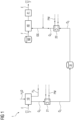
- FIG. 1 A schematic diagram of an energy system 1 according to a first example of the invention is shown. This diagram is highly simplified and shows only the essential components.
- the energy system 1 comprises an electrolyzer 10, with which water H 2 O can be electrolytically split into oxygen O 2 and hydrogen H 2. This occurs by absorbing electrical energy E, which can, for example, originate from a renewable energy source or, during periods of low electricity prices, from the electricity grid.
- the water H 2 O can be supplied to the electrolyzer 10 in deionized form.
- the electrolytically formed hydrogen H 2 can be used in various ways.
- the energy system 1 can be used within the energy system 1 as a reactant for a chemical synthesis or it can be stored in a hydrogen storage device for further use at another location, e.g., as fuel for a fuel cell, or in a
- the electrolytically produced oxygen is temporarily stored in liquefied form in an oxygen storage unit 31 for use within the same energy system 1.
- the oxygen is cooled to a cryogenic temperature, i.e., to a temperature below its boiling point at atmospheric pressure.
- the energy system 1 also comprises an internal combustion engine 40 and a generator 41 coupled to it.
- a fuel F can be burned, which is supplied from a fuel storage 60.
- This fuel can be, for example, a liquid or a gaseous fuel. It can be a fossil fuel such as natural gas or petroleum, or a fuel from renewable sources such as biogas or a synthetic fuel.
- the fuel can also be a synthesis gas with the main components hydrogen H 2 , carbon monoxide CO and carbon dioxide CO 2 from the thermochemical conversion (in particular a gasification reaction) of a calorific value-containing carbonaceous feedstock with a summary composition C X H y O z N u Si v with pure oxygen O 2 and water vapor H 2 O.
- the fuel F can generally be, in particular, carbonaceous.
- the generator 41 is driven by the internal combustion engine 40, so that when the fuel is burned, electrical power can be provided to a consumer via the generator 41.
- the chemical energy of the fuel F is converted into electrical energy E.
- Combustion within the internal combustion engine 40 is carried out according to the oxyfuel process, so that a gas with a particularly high oxygen content is used as the oxidation gas OG.
- the oxygen O 2 for this oxidation gas is taken (at least partially) from the described cryogenic oxygen storage 31, i.e., it is electrolytically produced oxygen.
- the unlabeled arrow in the right-hand part of the figure indicates that, in addition to this oxygen O 2 , the oxidation gas OG also contains a another component may be added, in particular carbon dioxide.
- the energy system 1 is characterized in that the electrolytically produced oxygen O 2 is stored in liquefied form and that a heat exchanger is used when cooling the oxygen to a cryogenic temperature and/or heating the oxygen from the cryogenic temperature.
- a heat exchanger is used when cooling the oxygen to a cryogenic temperature and/or heating the oxygen from the cryogenic temperature.
- Figure 1 Two such heat exchangers 21 and 22 are shown, namely a first 21 in the oxygen cooling path and a second 22 in the oxygen heating path.
- the heat exchanger 21 is flowed through, on the one hand, by originally warm oxygen O 2 and, on the other hand, by another process medium PM, which is originally colder than the incoming warm oxygen.
- This can therefore in particular be a fluid (i.e. liquid and/or gaseous) process medium PM, which advantageously fulfills another function within the energy system 1.
- the oxygen O 2 is cooled on its way through the heat exchanger, advantageously to a cryogenic temperature of -35 °C or less. It is also possible for the oxygen to be cooled in this heat exchanger 21 to a cryogenic temperature below its boiling point and thus to condense already in the heat exchanger 21. However, this can only be achieved with certain cryogenic process media and in particular with liquid nitrogen as the process medium PM.
- Cooling the oxygen to a cryogenic temperature already in the heat exchanger 21 is also not absolutely necessary. In order to achieve high energy efficiency during operation of the energy system 1, it is sufficient if the oxygen is pre-cooled to a cryogenic temperature in this heat exchanger 21 and then liquefied in a further step not explicitly shown here.
- the heat exchanger 22 is flowed through on the one hand by originally cold oxygen O 2 and on the other hand by another process medium PM, which is originally warmer than the incoming cold oxygen.
- This can also be a fluid process medium, which advantageously fulfills a further function within the energy system 1.
- the oxygen O 2 is heated from a cryogenic temperature to a higher temperature on its way through the heat exchanger, wherein the originally cold temperature level is used to cool the process medium PM. It is also possible for the oxygen to evaporate from its liquefied form in this heat exchanger 22.
- the process medium to be cooled can condense and in particular be liquefied therein, which facilitates subsequent storage of this process medium.
- the energy system 1 according to Figure 1 can be operated in two different operating modes.
- the first operating mode is used when, for example, a high level of electrical energy E is available in a higher-level power grid.
- the electrolyzer 10 is then operated with this energy E, and the oxygen produced is stored in the oxygen storage 31.
- the components in the left half of the Figure 1 active.
- the second operating mode comes into play when the electrical energy required by the consumers exceeds the supply from other sources.
- the internal combustion engine 40 is then operated, with the coupled generator 41 providing electrical power for the consumers. This is done using oxygen from the oxygen storage 31.
- the components in the right half of the Figure 1 active. At least in one of these halves, and thus also in one of the two operating modes, a heat exchanger 21 and/or 22 is used in the oxygen path.
- FIG 2 A similar schematic diagram of an energy system 1 according to a second example of the invention is shown.
- This energy system 1 is based on the basic design of the Figure 1 and is expanded by some optional components.
- the electrolytically formed hydrogen H 2 is fed to a synthesis reactor 71 as a reactant.
- the hydrogen H 2 can be compressed with a compressor 90 if required.
- Carbon dioxide CO 2 is fed to the synthesis reactor 71 as a further reactant.
- a carbon-based synthesis takes place in which the carbon dioxide is reduced by the hydrogen, whereby in this example a synthetic fuel is formed.
- the synthesis product can be a compound with the empirical formula C n H m O z or the synthesis product can comprise one or more compounds with such an empirical formula, where z can optionally also be 0.
- the fuel EF formed can be stored in a fuel storage 81.
- the carbon dioxide that is fed to the synthesis reactor 71 is, in the example of the Figure 2 recovered from the combustion and subsequently stored in a carbon dioxide storage 32.
- the carbon dioxide is liquefied and brought to a cryogenic temperature, e.g., in the range of approximately -50 °C. This cryogenic carbon dioxide is flowed through a heat exchanger 21a and heated there, whereby the oxygen also flowing through this heat exchanger 21a is cooled.
- the components in the right half of the figure are active, and fuel 60 is again burned in the internal combustion engine 41.
- This can optionally be (at least partially) the synthetic fuel EF, which was produced in the first operating mode from the hydrogen and the carbon dioxide.
- a fuel F from other sources can also be used.
- the flue gas RG formed during combustion is fed into a recovery device 50, in which the carbon dioxide contained in the flue gas is recovered.
- This recovery device 50 can in particular contain a dehumidification device in order to remove water produced during combustion from the flue gas.
- the recovered carbon dioxide can then be utilized in various ways, whereby the ratio of the two utilization paths can also be adjusted during the process if necessary.
- the recovery device 50 can comprise a connection for a cold partial flow extraction, with which comparatively cold carbon dioxide is extracted and mixed in a first path with the oxygen flowing towards the machine 40, whereby the oxidation gas OG supplied to the combustion is formed.
- the mixing ratio of these two components in the oxidizing gas OG can, in turn, be adapted to the other boundary conditions of the combustion and, in particular, can be varied over the course of the process.
- a fermentation gas or synthesis gas that already contains carbon dioxide can be used as fuel F. This carbon dioxide does not need to be removed from the fermentation gas or synthesis gas; rather, the amount of additional carbon dioxide added can be adjusted in each case so that the desired overall concentration and, for example, the desired flame temperature and power generation during combustion are achieved.
- the carbon dioxide is extracted from the recovery device 50 at a comparatively higher temperature level, for example, and first compressed with a compressor 90 and then fed to the heat exchanger 22 as an additional process medium.
- warm carbon dioxide and originally cold oxygen whereby the oxygen is heated and the carbon dioxide is cooled.
- the inflowing oxygen can in particular still be liquefied or, more generally, be at a cryogenic temperature.
- the carbon dioxide can be liquefied due to the heat transfer, which is particularly possible at a pressure above 5.2 bar.
- the heat exchanger 22 can advantageously have a degassing device with which oxygen and other lighter-boiling impurities such as nitrogen and noble gases can be removed from the liquid carbon dioxide.
- the liquefied carbon dioxide is then fed to the carbon dioxide storage 32, from which it can be consumed in the first operating mode as described.
- FIG 3 A similar schematic diagram of an energy system 1 according to a third example of the invention is shown.
- This energy system 1 is also based on the basic design of the Figure 1 and is extended by some optional components.
- carbon dioxide is recovered from the flue gas RG of the combustion and partly fed to the oxidation gas OG and partly used for other purposes. This other use is not shown for the sake of clarity, but liquefaction of the carbon dioxide can also take place in the heat exchanger 22.
- the electrolytically produced hydrogen H 2 is also utilized in the first operating mode in a hydrogen-based synthesis.
- the hydrogen is fed to a synthesis reactor 72, which in this example is designed for the synthesis of ammonia NH 3 and is accordingly fed with nitrogen N 2 as an additional reactant.
- a synthesis reactor 72 which in this example is designed for the synthesis of ammonia NH 3 and is accordingly fed with nitrogen N 2 as an additional reactant.
- further components can be arranged upstream of this synthesis reactor 72, such as a reactor for catalytic reaction, in which any residual oxygen content in the inflowing hydrogen is removed by catalytic reaction with hydrogen and condensation of the water formed.
- the ammonia NH 3 formed is stored in an ammonia storage tank 82, which may be preceded by additional components for cleaning, compressing, and/or cooling the ammonia formed.
- a heat exchanger can be used, for example, to cool the ammonia to a cryogenic temperature and heat another process medium, thereby enabling the ammonia to be stored in liquefied form without an additional compressor.
- the energy system of the Figure 3 a heat exchanger 21b, into which liquid nitrogen N 2 flows from a nitrogen storage unit 33 as an additional process medium.
- the originally liquid nitrogen is heated in the heat exchanger 21b, and the originally warm oxygen is cooled to a cryogenic temperature, whereby it can optionally condense already in the heat exchanger 21b.
- This advantageously enables liquefaction of the electrolytically formed oxygen without an additional compressor on the way to the oxygen storage unit 31.
- the inflowing liquid nitrogen N 2 evaporates in the heat exchanger and is then fed to the synthesis reactor 72 as a reactant, thus resulting in dual use for this process medium as well.
- the evaporated nitrogen can be recompressed via a compressor 90 and fed back to the nitrogen storage unit 33 as liquid nitrogen in a closed circuit.
- the compressor 90 in the nitrogen path is expediently designed as a high-pressure compressor, wherein the compressed gas is cooled to a relatively low temperature, e.g., between -30 °C and -50 °C.
- a relatively low temperature e.g., between -30 °C and -50 °C.
- an expansion which can be carried out either adiabatically or, if necessary, via an expansion turbine, and finally leads to the liquefaction of the nitrogen.
- This renewed liquefaction is particularly useful when more liquid nitrogen is required in the heat exchanger 21b than is subsequently consumed in the ammonia synthesis.
- the nitrogen can be stored in a closed refrigerant circuit recycled where there is no reactor for ammonia synthesis.
- FIG 4 A similar schematic diagram of an energy system 1 according to a fourth example of the invention is shown, in which the additional components of the two previous examples are combined.
- both a carbon-based synthesis in the synthesis reactor 71 and a nitrogen-based synthesis in the synthesis reactor 72 are carried out here.
- the electrolytically produced oxygen O 2 is sequentially cooled using two successive heat exchangers 21a and 21b and liquefied in the second heat exchanger 21b.
- Carbon dioxide CO 2 recovered from the combustion serves as a further process medium of the first heat exchanger 21a, and liquid nitrogen N 2 is introduced as a further process medium into the second heat exchanger. Both substances are used as reactants in the respective synthesis reactors after passing through the respective heat exchanger.
- the illustrated energy systems can optionally include further components, for example, additional cooling or heating devices, compressors, condensation stages, dehumidification stages, and/or purification stages.
- the recovered carbon dioxide can be freed from impurities that would interfere with the synthesis reactor 71, such as oxygen and sulfur.
- the nitrogen evaporated in heat exchanger 21b can be freed from impurities that would interfere with the synthesis reactor 72, such as sulfur, carbon monoxide, and carbon dioxide.
- the electrolytically produced gases oxygen and hydrogen can each first pass through a mist eliminator for dehumidification.
- These mist eliminators can each be connected to a cooling water circuit, which can also be used, in particular, to cool the synthesis reactors.
- the cooling water can, for example, have a temperature of a few degrees above freezing.
- the cold from this cooling water circuit can also be coupled into a building cooling system and relieve the load on a conventional air conditioning system with a compressor.
- the energy system can additionally include a heat pump (not shown here) or another heating device with which certain components can be heated for operation, for example, the optionally present reactor for the catalytic reaction of residual oxygen with hydrogen before the hydrogen is fed into the ammonia synthesis.
- the electrolyzer 10, the internal combustion engine 40, and/or one of the synthesis reactors 71, 72 can serve as the heat reservoir, as thermal energy is released during operation, so that heat removal is expedient here.
- Cryogenic gas streams can generally also be used for other purposes, e.g. to freeze water from oxygen or carbon dioxide before they are liquefied or to provide cooling capacity for a consumer, e.g. for building cooling.
Landscapes
- Chemical & Material Sciences (AREA)
- Engineering & Computer Science (AREA)
- Chemical Kinetics & Catalysis (AREA)
- Electrochemistry (AREA)
- Materials Engineering (AREA)
- Metallurgy (AREA)
- Organic Chemistry (AREA)
- Combustion & Propulsion (AREA)
- Mechanical Engineering (AREA)
- General Engineering & Computer Science (AREA)
- Inorganic Chemistry (AREA)
- Separation By Low-Temperature Treatments (AREA)
Priority Applications (1)
| Application Number | Priority Date | Filing Date | Title |
|---|---|---|---|
| EP23209081.1A EP4553192A1 (fr) | 2023-11-10 | 2023-11-10 | Système d'énergie pour fournir de l'énergie électrique |
Applications Claiming Priority (1)
| Application Number | Priority Date | Filing Date | Title |
|---|---|---|---|
| EP23209081.1A EP4553192A1 (fr) | 2023-11-10 | 2023-11-10 | Système d'énergie pour fournir de l'énergie électrique |
Publications (1)
| Publication Number | Publication Date |
|---|---|
| EP4553192A1 true EP4553192A1 (fr) | 2025-05-14 |
Family
ID=88778464
Family Applications (1)
| Application Number | Title | Priority Date | Filing Date |
|---|---|---|---|
| EP23209081.1A Pending EP4553192A1 (fr) | 2023-11-10 | 2023-11-10 | Système d'énergie pour fournir de l'énergie électrique |
Country Status (1)
| Country | Link |
|---|---|
| EP (1) | EP4553192A1 (fr) |
Citations (4)
| Publication number | Priority date | Publication date | Assignee | Title |
|---|---|---|---|---|
| EP2426236A1 (fr) * | 2010-09-03 | 2012-03-07 | Carbon-Clean Technologies AG | Procédé et installation de production de support d'énergie pour l'équilibrage neutre en dioxyde de carbone de pointes de production et de creux de production lors de la production d'énergie électrique et/ou pour la production d'un support d'énergie contenant de l'hydrocarbure |
| WO2013171107A2 (fr) * | 2012-05-14 | 2013-11-21 | Christian Mair | Système d'alimentation en carburant pour véhicules à stockage de dioxyde de carbone |
| DE102019216764A1 (de) * | 2019-10-30 | 2021-05-06 | Fraunhofer-Gesellschaft zur Förderung der angewandten Forschung e.V. | Vorrichtung umfassend zwei Teilsysteme, Verfahren zum Betreiben dieser Vorrichtung sowie Verkehrsmittel umfassend zumindest eines der Teilsysteme |
| US20230228463A1 (en) * | 2020-05-05 | 2023-07-20 | Eosgen-Technologies | Cooling system, air-conditioning system, motor assembly and associated methods |
-
2023
- 2023-11-10 EP EP23209081.1A patent/EP4553192A1/fr active Pending
Patent Citations (4)
| Publication number | Priority date | Publication date | Assignee | Title |
|---|---|---|---|---|
| EP2426236A1 (fr) * | 2010-09-03 | 2012-03-07 | Carbon-Clean Technologies AG | Procédé et installation de production de support d'énergie pour l'équilibrage neutre en dioxyde de carbone de pointes de production et de creux de production lors de la production d'énergie électrique et/ou pour la production d'un support d'énergie contenant de l'hydrocarbure |
| WO2013171107A2 (fr) * | 2012-05-14 | 2013-11-21 | Christian Mair | Système d'alimentation en carburant pour véhicules à stockage de dioxyde de carbone |
| DE102019216764A1 (de) * | 2019-10-30 | 2021-05-06 | Fraunhofer-Gesellschaft zur Förderung der angewandten Forschung e.V. | Vorrichtung umfassend zwei Teilsysteme, Verfahren zum Betreiben dieser Vorrichtung sowie Verkehrsmittel umfassend zumindest eines der Teilsysteme |
| US20230228463A1 (en) * | 2020-05-05 | 2023-07-20 | Eosgen-Technologies | Cooling system, air-conditioning system, motor assembly and associated methods |
Non-Patent Citations (1)
| Title |
|---|
| "IRES", AHE, vol. 16, 2022, pages 551 - 562 |
Similar Documents
| Publication | Publication Date | Title |
|---|---|---|
| AT517934B1 (de) | Anlage und Verfahren zur gaskompressionsfreien Rückgewinnung und Speicherung von Kohlenstoff in Energiespeichersystemen | |
| DE102014105237B3 (de) | Verfahren und Vorrichtung zum Speichern und Rückgewinnen von Energie | |
| DE102012214907B4 (de) | Dampfkraftanlage zur Erzeugung von elektrischer Energie nach dem Oxyfuel-Verfahren | |
| DE102013102969B4 (de) | Verfahren zum Herstellen von vorwiegend flüssigen Kohlenwasserstoffen sowie Anordnung | |
| EP3052435B1 (fr) | Procédé de stockage d'énergie électrique | |
| AT514614B1 (de) | Verfahren und System zum Speichern von Energie | |
| WO2018019875A1 (fr) | Procédé et dispositif de fabrication du méthanol | |
| EP4028489B1 (fr) | Dispositif et procédé comprenant deux sous-systèmes destinés à utiliser des combustibles à base de carbone dans des moteurs à combustion interne dans un fonctionnement en circuit, permettant de réutiliser le produit d'oxydation accumulé et d'entraîner un agent oxydant sur le moyen de transport | |
| EP3491172A1 (fr) | Procédé et installaton de production d'hydrocarbures | |
| DE102010013660A1 (de) | Verfahren und Vorrichtung zur Speicherung von Energie | |
| DE69729038T2 (de) | Kraftwerk mit Trennung und Rückgewinnung von Kohlenstoffdioxid | |
| WO2013034130A2 (fr) | Séquestration écologique de dioxyde de carbone/augmentation de la quantité de bioénergie pouvant être obtenue à partir d'une biomasse | |
| EP4026932A1 (fr) | Procédé de décarbonisation d'un site industriel | |
| EP4553192A1 (fr) | Système d'énergie pour fournir de l'énergie électrique | |
| EP2526177B1 (fr) | Dispositifs sans émission pour effectuer des travaux mécaniques | |
| WO2013171107A2 (fr) | Système d'alimentation en carburant pour véhicules à stockage de dioxyde de carbone | |
| DE102020210478A1 (de) | Verfahren zur Wasserstoffsynthese unter Wärmenutzung aus einem Wärmenetzwerk mittels einem Hochtemperaturelektrolysesystem | |
| WO2011089169A2 (fr) | Procédé pour exploiter l'énergie temporairement superflue relativement à l'utilisation momentanée du courant dans un réseau électrique | |
| EP2348253A1 (fr) | Procédé d'exécution d'un travail mécanique sans émission | |
| EP4414545A1 (fr) | Procédé de fonctionnement d'une turbine à gaz avec séparation de co2 | |
| EP4635905A1 (fr) | Procédé et installation de production d'un produit d'hydrogène à l'aide d'ammoniac | |
| EP4501894A1 (fr) | Procédé de production de méthanol utilisant la chaleur perdue d'un électrolyseur | |
| DE102021125884A1 (de) | Verfahren und Vorrichtung zur Herstellung eines methanhaltigen Produktgases | |
| WO2025190595A1 (fr) | Procédé de fonctionnement d'un système de stockage pour une application power-to-x | |
| DE102010060595A1 (de) | Stromerzeugung aus tiefkalt verflüssigten Gasen |
Legal Events
| Date | Code | Title | Description |
|---|---|---|---|
| PUAI | Public reference made under article 153(3) epc to a published international application that has entered the european phase |
Free format text: ORIGINAL CODE: 0009012 |
|
| STAA | Information on the status of an ep patent application or granted ep patent |
Free format text: STATUS: THE APPLICATION HAS BEEN PUBLISHED |
|
| AK | Designated contracting states |
Kind code of ref document: A1 Designated state(s): AL AT BE BG CH CY CZ DE DK EE ES FI FR GB GR HR HU IE IS IT LI LT LU LV MC ME MK MT NL NO PL PT RO RS SE SI SK SM TR |
|
| STAA | Information on the status of an ep patent application or granted ep patent |
Free format text: STATUS: REQUEST FOR EXAMINATION WAS MADE |
|
| 17P | Request for examination filed |
Effective date: 20250603 |