EP4553220A1 - Seil mit internen schmiermitteldepots, seilbahn mit dem seil und verfahren zur herstellung des seils - Google Patents
Seil mit internen schmiermitteldepots, seilbahn mit dem seil und verfahren zur herstellung des seils Download PDFInfo
- Publication number
- EP4553220A1 EP4553220A1 EP24211836.2A EP24211836A EP4553220A1 EP 4553220 A1 EP4553220 A1 EP 4553220A1 EP 24211836 A EP24211836 A EP 24211836A EP 4553220 A1 EP4553220 A1 EP 4553220A1
- Authority
- EP
- European Patent Office
- Prior art keywords
- rope
- lubricant
- core
- rope core
- longitudinal elements
- Prior art date
- Legal status (The legal status is an assumption and is not a legal conclusion. Google has not performed a legal analysis and makes no representation as to the accuracy of the status listed.)
- Pending
Links
Images




Classifications
-
- D—TEXTILES; PAPER
- D07—ROPES; CABLES OTHER THAN ELECTRIC
- D07B—ROPES OR CABLES IN GENERAL
- D07B1/00—Constructional features of ropes or cables
- D07B1/14—Ropes or cables with incorporated auxiliary elements, e.g. for marking, extending throughout the length of the rope or cable
- D07B1/141—Ropes or cables with incorporated auxiliary elements, e.g. for marking, extending throughout the length of the rope or cable comprising liquid, pasty or powder agents, e.g. lubricants or anti-corrosive oils or greases
- D07B1/144—Ropes or cables with incorporated auxiliary elements, e.g. for marking, extending throughout the length of the rope or cable comprising liquid, pasty or powder agents, e.g. lubricants or anti-corrosive oils or greases for cables or cable components built-up from metal wires
-
- D—TEXTILES; PAPER
- D07—ROPES; CABLES OTHER THAN ELECTRIC
- D07B—ROPES OR CABLES IN GENERAL
- D07B1/00—Constructional features of ropes or cables
- D07B1/16—Ropes or cables with an enveloping sheathing or inlays of rubber or plastics
- D07B1/165—Ropes or cables with an enveloping sheathing or inlays of rubber or plastics characterised by a plastic or rubber inlay
- D07B1/167—Ropes or cables with an enveloping sheathing or inlays of rubber or plastics characterised by a plastic or rubber inlay having a predetermined shape
Definitions
- the invention relates to a rope according to the preamble of claim 1, a cable car according to claim 13 and a method according to the preamble of claim 14.
- Cableway traction wire ropes and cableway hoist wire ropes with a rope core and with a plurality of longitudinal elements stranded around the rope core have already been proposed.
- the object of the invention is, in particular, to provide a generic device with advantageous usage properties. This object is achieved by the features of the independent patent claims, while advantageous embodiments and further developments of the invention can be found in the subclaims.
- the invention is based on a rope, in particular a wire rope, preferably a cable car traction wire rope and/or a cable car hoist wire rope, with a rope core and with a plurality of longitudinal elements, in particular wires or wire strands, which are stranded around the rope core.
- the rope has at least a first lubricant reservoir, which is arranged on a (first)
- the contact area between a first longitudinal element of the longitudinal elements and the rope core or between an insert element arranged between adjacent longitudinal elements of an innermost rope layer of the rope and the rope core is limited. This can advantageously increase the service life, in particular by reducing internal wear.
- the lubricant reservoir in particular in an inner region of the rope, high friction of the outer surfaces of the rope can be achieved despite the use of lubricant, which is particularly essential for cable car ropes, which are often driven by friction sheaves or the like.
- the invention can limit lubrication of the rope to the areas between the longitudinal elements and the rope core.
- the use of local and limited lubricant reservoirs can achieve high economic and/or ecological efficiency.
- the amount of lubricant used to achieve the desired effect can be kept particularly low, thereby advantageously minimizing resource consumption and advantageously resulting in a cost advantage.
- a reserve lubricant reservoir or a lubricant reservoir whose lubricant is only used as the rope ages or reaches the longitudinal elements, in particular the wire strands, can be created.
- the rope is designed in particular as a wire strand rope, e.g. as a 6x19 Seale wire strand rope, as a 6x25 Filler wire strand rope, as a 6x29 Filler wire strand rope or as a 6x36 Warrington Seale wire strand rope.
- the rope is designed in particular as a wire rope, preferably a wire strand rope.
- the rope, in particular the wire strand rope can be a non-compacted rope or as a compacted rope.
- the compacted rope can comprise compacted strands, in particular strands with compacted wires.
- a "longitudinal element” is understood to mean, in particular, an elongated and/or thin and/or at least mechanically bendable and/or flexible body.
- the wire(s) of the longitudinal element have(s) an at least substantially constant, in particular circular or elliptical, cross-section along their longitudinal direction(s).
- the wires are formed as round wires.
- the wire it is also conceivable for the wire to be formed, at least in part or entirely, as a flat wire, a square wire, a polygonal wire, and/or a profiled wire having another profile shape.
- the wire and/or the longitudinal element has a particularly corrosion-resistant coating and/or sheathing such as a zinc coating and/or an aluminum-zinc coating and/or a plastic coating and/or a PET coating and/or a metal oxide coating and/or a ceramic coating or the like.
- a particularly corrosion-resistant coating and/or sheathing such as a zinc coating and/or an aluminum-zinc coating and/or a plastic coating and/or a PET coating and/or a metal oxide coating and/or a ceramic coating or the like.
- the rope is particularly designed as a single-layer rope. However, a design as a multi-layer rope is also conceivable.
- the rope can also have insert elements between the longitudinal elements or can be designed without insert elements between the longitudinal elements.
- at least some of the longitudinal elements of the rope can be made of natural or synthetic fibers.
- at least some of the longitudinal elements, preferably all of the longitudinal elements are made of a metal, preferably of steel.
- the steel of at least some of the longitudinal elements made of metal, preferably all of the longitudinal elements can be a high-strength steel with a tensile strength of 1000 N/mm 2 and more.
- the longitudinal elements made of metal in particular all of the longitudinal elements, from non-high-strength steel with tensile strengths below 1000 N/mm 2 is also conceivable.
- the steel of at least some of the longitudinal elements made of metal, preferably all of the Longitudinal elements can be made of stainless steel.
- the wire is formed at least partially or entirely from a composite material and/or an inorganic non-metallic material and/or a ceramic material.
- the wire could also be formed as a composite wire, for example as a metal-organic composite wire and/or a metal-inorganic composite wire and/or a metal-polymer composite wire and/or a metal-metal composite wire or the like.
- the longitudinal elements of a rope layer are stranded with a lang lay, for example a right lay or a left lay.
- the longitudinal elements could also be stranded with a regular lay.
- the rope is designed as a cable car traction wire rope and/or cable car haulage wire rope for a passenger cable car, for example a mountain railway or a light rail system, and/or for a material cable car, in particular underground, e.g. in a mine, or above ground, e.g. in the mountains or in a city.
- the rope could be designed as a cable car traction wire rope and/or cable car haulage wire rope for transporting persons in accordance with the standard DIN EN 12385-8:2003-03 and/or with the standard ANSI B77.1-2022.
- the cable car traction wire rope and/or cable car haulage wire rope is preferably designed for an operating time of several thousand hours, e.g. more than 3000 hours, per year.
- the rope is, in particular, an endless rope, preferably a revolving hoist rope or a revolving traction rope of a cable car.
- the cable car traction wire rope and/or cable car hoist wire rope is moved during operation and deflected at at least one, preferably at least two points, e.g., by a deflection wheel/drive pulley of a cable car (end) station.
- the rope in an assembled state, is wrapped around at least one drive element, in particular around the drive pulley, of a drive unit of a cable car.
- "Provided” is to be understood as meaning, in particular, specially designed and/or equipped. This means that a When an object is intended for a specific function, it should be understood in particular that the object fulfils and/or executes this specific function in at least one application and/or operating state.
- the rope core is particularly designed as a plastic rope core.
- the rope core particularly forms a rope core.
- the rope core particularly forms a rope heart.
- the rope core particularly forms a rope insert.
- the rope core is particularly arranged in the center of the rope, preferably in a vertical rope cross-section.
- the longitudinal elements of a rope layer are preferably arranged on an imaginary circular line in the vertical cross-sectional view of the rope.
- the centers of the longitudinal elements of the rope are each arranged equidistant from the center of the rope/rope core in the vertical cross-sectional view of the rope.
- the rope core can have a flat, particularly unmachined, cylindrical outer surface.
- the rope core it is also conceivable for the rope core to have at least one helical groove, preferably a plurality of helical grooves, preferably a number of helical grooves corresponding to the number of longitudinal elements of the rope, on an outer surface.
- the grooves can be introduced into the rope core prior to stranding, or alternatively, the rope core could also be formed as a solid polymer core that deforms when heated during stranding.
- the rope core could also be formed as a fiber core comprising a plurality of fibers, in particular PP fibers.
- the outer sheath surface of the rope core is in particular the surface of the rope core that delimits the rope core outwards in a radial direction of the rope perpendicular to the longitudinal direction of the rope (pointing towards the longitudinal elements).
- a longitudinal element stranded around the rope core is guided/wound in a helical/helical manner around the rope core.
- a lay length of the longitudinal elements is at least 4*d and preferably at least 6*d and/or at most 12*d and preferably at most 9*d.
- the longitudinal elements are advantageously wound around the core in such a way arranged around such that they are contact-free and/or spaced apart from one another with respect to their longitudinal directions.
- the rope has a constant diameter.
- the diameter of the rope can be suitably selected for the specific application. In particular, the diameter is at least 10 mm and/or at most 100 mm. If the rope is a traction rope, for example, the diameter is in particular at least 10 mm and advantageously at least 20 mm and/or at most 80 mm and advantageously at most 70 mm. If the rope is a hoist rope, for example, the diameter is in particular at least 30 mm and advantageously at least 40 mm and/or at most 100 mm and advantageously at most 90 mm. However, rope diameters deviating from this are also conceivable.
- the rope preferably has a constant cross-section or at least a cross-section that occurs periodically along its longitudinal direction.
- the cross-section can be circular, in particular in the case that the rope has suitable insert elements between longitudinal elements running on its surface, which advantageously fill spaces between the longitudinal elements. It is also conceivable that the cross-section corresponds to that of a conventional wire rope with strands arranged around a rope core.
- the longitudinal elements each have an at least substantially constant cross-section.
- the longitudinal elements are wire strands, which in turn can be constructed from several individual wires, which in particular can be at least substantially identical to one another.
- a longitudinal element for example designed as a wire strand, to have different individual wires and/or other components such as inserts, fibers, sheathing elements, or the like.
- the longitudinal element advantageously has a lay length that corresponds to at least five times and preferably at least seven times and/or at most 15 times and preferably at most eleven times the diameter of the longitudinal element. In principle, Longitudinal elements of different lay can be used.
- lay direction of the wire rope can be identical or opposite to the lay direction of the longitudinal elements or at least individual longitudinal elements.
- At least substantially identical objects are understood to mean, in particular, objects constructed in such a way that they can each fulfill a common function and, apart from manufacturing tolerances, preferably differ in their construction only by individual elements that are immaterial to the common function.
- Identical objects are also understood to mean, in particular, objects that are symmetrical to one another.
- an object has an "at least substantially constant cross-section" is to be understood in particular to mean that for any first cross-section of the object along at least one direction and any second cross-section of the object along the direction, a minimum surface area of a differential area formed when the cross-sections are placed on top of one another is a maximum of 20%, advantageously a maximum of 10% and particularly advantageously a maximum of 5% of the surface area of the larger of the two cross-sections.
- the rope core has a larger maximum diameter than each of the longitudinal elements stranded with the rope core. This advantageously prevents mutual contact of the longitudinal elements.
- the maximum diameter of the rope core is at most 120%, preferably at most 100%, advantageously at most 66% and preferably at most 35% larger than a maximum diameter of one of the longitudinal elements, in particular of the longitudinal element of the longitudinal elements with the largest diameter.
- the maximum diameter of the rope core can be at most 35% larger than a maximum diameter of one of the longitudinal elements, in particular of the longitudinal element of the longitudinal elements with the largest diameter, while preferably in an 8-strand rope the maximum The diameter of the rope core can be significantly greater than 35%, but at most 120% greater than the maximum diameter of one of the longitudinal elements, in particular of the longitudinal element of the longitudinal elements with the largest diameter.
- the maximum diameter of the rope core is at least 10%, preferably at least 20%, advantageously at least 30%, and preferably at least 35% greater than a maximum diameter of one of the longitudinal elements, in particular of the longitudinal element of the longitudinal elements with the largest diameter.
- the maximum diameter of the rope core is formed by the minimum possible diameter of an imaginary circular ring, which, when displaced along the longitudinal extent of the rope core, always includes the entire cross-section of the rope core over the entire longitudinal extent of the rope core.
- the first lubricant depot and preferably also each further lubricant depot, is spatially limited locally to a rope region located entirely within the interior of the rope.
- the rope region to which the first lubricant depot, in particular one of the lubricant depots, is spatially limited extends spirally or helically around the rope core.
- only a single longitudinal element of the longitudinal elements of the rope, preferably the first longitudinal element is arranged partially within the first lubricant depot and/or adjacent to the first lubricant depot.
- a separate lubricant depot can be assigned to a plurality of longitudinal elements and/or a plurality of insert elements, preferably to each longitudinal element and/or to each insert element.
- the respective lubricant depot extends along an entire length of the respective longitudinal element and/or the respective insert element.
- a plurality of separate lubricant depots are arranged one behind the other along the entire length of a longitudinal element.
- a contact area between the first longitudinal element and the rope core is defined at least by the contacting surface sections of the rope core and The contact area is formed by the longitudinal element as well as all areas between the outer contact points of the rope core and the longitudinal element.
- the contact area can be formed by the recess of one of the grooves.
- areas directly adjacent to direct contact points inside the longitudinal element can also be counted as part of the contact area.
- the contact area runs around the rope core with an identical lay direction and lay length as the corresponding longitudinal element.
- the rope have at least one second lubricant reservoir, which is in particular different from the first lubricant reservoir and is limited to a (second) contact area spirally encircling the rope core between a second longitudinal element of the longitudinal elements, in particular different from the first longitudinal element, and the rope core.
- a number of lubricant reservoirs of the rope corresponds to a number of longitudinal elements of the rope, in particular to an innermost rope layer of the rope.
- each of the longitudinal elements of the rope is assigned its own lubricant reservoir.
- the rope has at least one (further) second lubricant depot, which is in particular different from the first lubricant depot and is limited to a (third) contact area spirally encircling the rope core between a second insert element, which is in particular different from the first insert element, and the rope core.
- a number of lubricant depots of the rope then corresponds to a number of insert elements or a sum of insert elements and longitudinal elements of the rope, in particular to an innermost rope layer of the rope.
- each of the insert elements of the rope is assigned its own lubricant depot.
- the Lubricant reservoirs are non-intersecting.
- the lubricant reservoirs circulate uniformly around the rope core.
- first lubricant depot(s) and the second lubricant depot(s), preferably all lubricant depots of the rope are spatially separated from one another, high efficiency, in particular cost efficiency and/or resource utilization efficiency, can advantageously be achieved, and/or high operational reliability can be achieved, in particular by preventing lubricant from escaping onto a surface of the rope.
- no or almost no exchange of lubricant takes place between adjacent lubricant depots, in particular any lubricant depots, and especially the first lubricant depot and the second lubricant depot.
- the lubricant depots are arranged around the rope core in mutually separate cross-sectional areas.
- the rope have a number of lubricant reservoirs corresponding to a number of longitudinal elements of the innermost rope layer or a number of insert elements or a sum of longitudinal elements of the innermost rope layer and insert elements of the rope, each of which is limited to contact areas between the respective longitudinal element and the rope core, preferably spatially separated from one another, encircling the rope core in a spiral.
- This can advantageously increase the service life of the rope.
- the lubricant reservoir(s) of the rope designed as a cableway traction wire rope and/or cableway hoist wire rope contain(s) a lubricant that deviates significantly from the specifications of Annex A "General requirements for lubricants" of the standard EN 12385-8:2002 (D).
- a lubricant that deviates significantly from the specifications of Annex A "General requirements for lubricants" of the standard EN 12385-8:2002 (D).
- the lubricant reservoirs located inside the rope can advantageously ensure that the entire rope conforms to standards despite the use of non-standard lubricants. This can advantageously result in a standard-compliant cableway traction wire rope and/or cableway haulage wire rope, which has a particularly long service life and smooth running.
- Annex A "General Requirements for Lubricants" of the EN 12385-8:2002 (D) standard includes at least the following requirements for the lubricant.
- the lubricant must have a coefficient of friction of more than 0.22 at 20°C, as determined in accordance with DIN 21258:1986.
- the rope must not experience a volume change of more than 20% and a hardness reduction of more than 10° Shore A during a 14-day immersion test according to DIN 53521:1987-11, in which the rope was immersed in a lubricant with a temperature above 20°C.
- the lubricant must have an adhesive strength and plasticity in accordance with point 4.2 of DIN 21258:1986.
- the lubricant must have a water-soluble acid content that complies with point 4.4 of DIN 21258:1986.
- the lubricant must have a flash point above 55°C that complies with DIN EN ISO 2592:2018-01.
- the lubricant depot(s) of the cable car traction wire rope and/or cable car hoist wire rope comprise(s) a lubricant which has a friction coefficient, determined in particular according to the standard DIN 21258:2007-10, of less than 0.22, in particular of less than 0.20, preferably of less than 0.10 and preferably of less than 0.05,
- a friction coefficient determined in particular according to the standard DIN 21258:2007-10, of less than 0.22, in particular of less than 0.20, preferably of less than 0.10 and preferably of less than 0.05
- a lubricant contained in the lubricant reservoir(s) comprises an EP (Extreme Pressure) additive
- the EP additive can be a sulfur-crosslinked organic compound, a phosphorus-containing compound such as a dialkyl dithiophosphate and/or a dimercaptothiadiazole derivative, and/or a chloroparaffin.
- the lubricant itself can, for example, be a (mineral oil) soap-based grease (e.g., based on paraffins, olefins, naphthenes, or aromatics) or a synthetic-based grease.
- the lubricant could be an aluminum complex soap-based grease with EP additives.
- the rope core have at least one first groove running spirally around the rope core, within which the first lubricant reservoir is arranged. This advantageously makes it possible to achieve particularly reliable and/or durable localization of the lubricant reservoirs.
- ropes with lubricant reservoirs according to the invention are also conceivable, the rope cores of which are free of grooves, i.e., cylindrical, or designed as a fiber core.
- the number of grooves preferably corresponds to the number of lubricant reservoirs and/or the number of longitudinal elements of the rope.
- first lubricant reservoir is arranged in a first groove, into which the first longitudinal element is inserted, while the second lubricant reservoir is arranged in a second groove, into which the second longitudinal element is inserted.
- first groove into which the first longitudinal element is inserted
- second lubricant reservoir is arranged in a second groove, into which the second longitudinal element is inserted.
- first groove of the rope core spatially delimits the first lubricant depot at least in the circumferential direction of the rope core, a particularly high efficiency, in particular cost efficiency and/or resource utilization efficiency, can advantageously be achieved, and/or a particularly high operational reliability can be achieved, in particular by preventing lubricant from escaping onto a surface of the rope.
- the first groove has a groove cross-sectional shape that at least substantially corresponds to an outer cross-sectional shape of the first longitudinal element, a particularly high degree of fit can advantageously be achieved. This can advantageously ensure that the lubricant does not leave the lubricant reservoir.
- the rope have insert elements arranged between adjacent longitudinal elements, which are arranged in the circumferential direction between lubricant depots of the adjacent longitudinal elements.
- the insert elements are made of a plastic, for example a polymer.
- the insert elements form filler elements that at least partially, in particular largely, fill the free spaces between longitudinal elements.
- the insert elements could also be formed from a plurality of fibers, e.g. plastic fibers.
- the insert element, preferably each insert element rests in contact with at least two adjacent longitudinal elements of the longitudinal elements of the rope.
- the insert elements to touch the rope core in circumferential regions of the rope core between the lubricant depots.
- a cable car in particular a passenger cable car and/or a material cable car, with the cable is proposed.
- a long service life of the cable car and/or particularly quiet operation of the cable car can be achieved.
- a method for producing the rope in particular the wire rope, preferably the cable car traction wire rope and/or the cable car hoist wire rope, is proposed, wherein a lubricant is applied in regions to an outer surface of the rope core and/or to a rear side of the longitudinal elements or insert elements facing the rope core, in particular those forming the innermost rope layer of the rope.
- a lubricant is applied, preferably continuously, during a stranding process in which the longitudinal elements are wrapped around the rope core.
- lubricant nozzles dispensing the lubricant are rotated around a longitudinally conveyed rope core.
- the rope core is rotationally fixed.
- the rope core it is also conceivable for the rope core to rotate during longitudinal conveyance. In this case, the lubricant nozzles could also rotate or remain stationary to create the spiral-shaped lubricant strips around the rope core.
- the lubricant is also introduced into grooves in the rope core that run spirally around the rope core, the spatial containment of the lubricant deposits created in the rope can be advantageously improved.
- the longitudinal elements are twisted spirally around the rope core and brought into contact with the rope core.
- lubrication and stranding are carried out continuously and continuously.
- the amount of lubricant applied is selected such that the lubricant(s) is/cannot be forced outward from the rope after stranding and that the lubricant deposits do not bond with one another after stranding and/or lubricant is not exchanged between the lubricant deposits.
- the rope according to the invention, the cableway according to the invention, and/or the method according to the invention are not intended to be limited to the application and embodiment described above.
- the rope according to the invention, the cableway according to the invention, and/or the method according to the invention may have a number of individual elements, components, and units that differs from the number stated herein to fulfill a function described herein.
- the Figure 1 shows a schematic and exemplary cable car 50.
- the cable car 50 is designed as a passenger transport cable car.
- the cable car 50 could alternatively be designed as a material cable car.
- the cable car 50 comprises a cable 10.
- the cable 10 is designed as a haulage cable of the cable car 50.
- the cable 10 could also be designed as a traction cable of a cable car 50.
- the cable car 50 is designed, for example, as a 3-cable revolving cable car.
- other cable car types with the cable 10 are also conceivable.
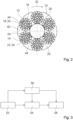
- the Figure 2 shows a schematic cross-sectional view of the rope 10.
- the rope 10 is designed as a wire rope.
- the rope 10 is designed as a cable car traction wire rope.
- the rope 10 could also be designed as a cable car hoist wire rope.
- the rope 10 comprises a rope core 20.
- the rope 10 comprises a A plurality of longitudinal elements 12, 14.
- the rope core 20 is made of a material with a lower modulus of elasticity than the longitudinal elements 12, 14.
- the rope core 20 is made of a material with a lower modulus of compression than the longitudinal elements 12, 14.
- the rope core 20 is non-metallic.
- the rope core 20 is made of a plastic.
- the rope core 20 is designed as a monolithic component.
- the rope core 20 is manufactured as an extruded component.
- the rope core 20 could also be designed and/or manufactured differently, e.g. from a stranded (PP) split fiber yarn.
- the Figure 2 The rope core 20 shown as an example has a cylindrical outer surface 26.
- the Figure 2 The rope core 20 shown as an example has a groove-free outer surface 26.
- the Figure 2 The rope core 20 shown as an example is made of solid material. However, it is also conceivable that the rope core 20 is hollow.
- the rope 10 shown as an example comprises six longitudinal elements 12, 14.
- the longitudinal elements 12, 14 are stranded around the rope core 20.
- the longitudinal elements 12, 14 are at least substantially identical to one another.
- the longitudinal elements 12, 14 are designed as wire strands.
- the wire strands each comprise a plurality of wires.
- the wires of the wire strands are made of steel.
- the wires of the wire strands are steel wires.
- the rope 10 shown as an example is a 6x36 Warrington-Seale wire strand rope.
- the rope 10 has insert elements 42, 44.
- the insert elements 42, 44 are arranged between the individual stranded longitudinal elements 12, 14.
- the insert elements 42, 44 extend helically around the rope core 20.
- the insert elements 42, 44 are made of a polymer.
- Each of the insert elements 42, 44 arranged between two adjacent longitudinal elements 12, 14 is arranged in the circumferential direction 32 of the rope 10 between two adjacent lubricant depots 16, 22
- the rope 10 has a first lubricant reservoir 16.
- the rope 10 has a second lubricant reservoir 22.
- the rope 10 has further lubricant reservoirs
- the number of lubricant depots 16, 22 of the rope 10 corresponds to the number of longitudinal elements 12, 14 (here: 6) of an innermost rope layer 34 of the rope 10.
- the lubricant depots 16, 22 are each filled with a lubricant 30 / formed by a lubricant accumulation.
- the first lubricant depot 16 is limited to a first contact area 18. In the first contact area 18, the rope core 20 and the first longitudinal element 12 touch each other.
- the first contact area 18 runs spirally around the rope core 20 (see also Fig. 5 or 7 ).
- the second lubricant reservoir 22 is limited to a second contact area 24.
- the rope core 20 and the second longitudinal element 14 touch each other.
- the second contact area 24 runs spirally around the rope core 20 (see also Fig. 5 or 7 ).
- the first lubricant reservoir 16 and the second lubricant reservoir 22 are spatially completely separated from one another. All lubricant reservoirs 16, 22 of the rope 10 are spatially completely separated from one another. All lubricant reservoirs 16, 22 of the rope 10 extend to one another without crossing.
- the lubricant 30 contained in the lubricant reservoirs 16, 22 deviates significantly from the specifications of Annex A "General Requirements for Lubricants" of the standard EN 12385-8:2002 (D).
- the lubricant 30 contained in the lubricant reservoirs 16, 22 has a friction coefficient of less than 0.2.
- the friction coefficient is determined according to the standard DIN 21258:2007-10 (item 5).
- the content of the standards DIN 21258:2007-10 and/or EN 12385-8:2002 (D), including Annex A, is hereby incorporated in its entirety by reference into this disclosure.
- the lubricant 30 also has a friction coefficient greater than 0.02.
- the lubricant 30 contained in the lubricant depots 16, 22 comprises an EP (Extreme Pressure) additive 38 (see also Fig. 7 ). All lubricant reservoirs 16, 22 contain the same lubricant 30.
- the Figure 3 shows a schematic flow diagram of a method for producing the rope 10.
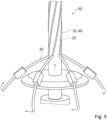
- the Figures 4 and 5 show sections of a production device 60 in operation for producing the rope 10.
- the rope core 20 is produced, for example by extrusion (see also Fig. 4 ).
- the rope core 20 could also be designed and/or manufactured differently, e.g., from a stranded (PP) split fiber yarn.
- the rope core 20 can be produced in a cylindrical shape or provided with spiral grooves on a cylindrical surface.
- the lubricant 30 is applied in regions, in particular in strips, to an outer surface 26 of the rope core 20.
- the lubricant 30 is applied to the rope core 20 during a longitudinal movement of the rope core 20, so that adhering lubricant strips 46 form on the outer surface 26 of the rope core 20 (see also Figures 4 or 5 ).
- the applied lubricant strips 46 then spiral around the rope core 20.
- the lubricant 30 is applied to a rear side 36 of the longitudinal elements 12, 14 forming the innermost rope layer 34 of the rope 10, facing the rope core 20.
- the lubricant 30 is applied to the rope core 20 and/or to the longitudinal elements 12, 14 by means of lubricant nozzles 40 (see also Figures 4 or 5 ).
- the lubricant nozzles 40 dispensing the lubricant 30 are preferably rotated uniformly around the longitudinally moving rope core 20. If the rope core 20 has been provided with grooves 48 spirally encircling the rope core 20 in the previous manufacturing step 52, the lubricant 30 is then introduced into the grooves 48 of the rope core 20 spirally encircling the rope core 20 by means of the lubricant nozzles 40 in the current manufacturing step 56. In at least one further manufacturing step 58, immediately after the application of the lubricant 30, the longitudinal elements 12, 14 are stranded spirally around the rope core 20 and are thereby brought into contact with the rope core 20. In the manufacturing step 58, the insert elements 42, 44 are also stranded around the rope core 20 together with the longitudinal elements 12, 14 at the same time.
- the Figure 6 shows a schematic cross-sectional view of an alternative rope 10', which differs from the rope 10 of the Figure 2 differs only in the design of the cable core 20'.
- the alternative cable core 20' has grooves 48 running spirally around the alternative cable core 20'.
- Each of the longitudinal elements 12, 14 is inserted into one of the grooves 48.
- the grooves 48 each have a groove cross-sectional shape that at least substantially corresponds to an outer cross-sectional shape of the associated longitudinal element 12, 14.
- the lubricant depots 16, 22 are each arranged within a groove 48 of the grooves 48.
- the grooves 48 of the alternative cable core 20' spatially delimit the respective lubricant depots 16, 22 in the circumferential direction 32 of the alternative cable core 20'.
- the Figure 7 shows schematically a side view of a partial section of an alternative rope core 20' having the grooves 48 ("naked") with the lubricant 30 introduced into the grooves 48.
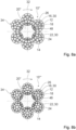
- the Figures 8a and 8b show schematic plan views of cross sections of further alternative ropes 10", 10'", which differ from the ropes 10, 10' of the preceding figures by the design of the longitudinal elements 12, 14 and the rope core 20".
- the longitudinal elements 12, 14 of the first further alternative rope 10" are in the Figure 8a designed as 21-filler wire strands.
- the longitudinal elements 12, 14 of the second alternative rope 10′′′ are in the Figure 8b For example, they are designed as 29-filler wire strands.
- the further alternative ropes 10", 10" are designed without insert elements 42, 44. Alternatively, however, the further alternative ropes 10", 10" could also have insert elements 42, 44 between the longitudinal elements 12, 14.
- the further alternative ropes 10", 10" each have a further alternative rope core 20".
- the further alternative rope core 20" has 26 grooves 48 on its outer surface.
- the grooves 48 of the further alternative rope core 20" are designed differently in shape and number than the grooves 48 of the alternative rope core 20'.
- the Figure 9 shows a schematic cross-sectional view of a first other alternative rope 10a, which differs from the rope 10 of the Figure 2 only by the arrangement of lubricant reservoirs 16, 16a.
- the Figure 9 to the Figure 2 The difference in lubricant depot arrangements shown can also be applied to the embodiments of the Figures 6 to 8b
- the data in the Figure 9 The rope 10a shown as an example comprises six longitudinal elements 12, 14.
- the rope 10a has insert elements 42, 44.
- the insert elements 42, 44 are arranged between the individual stranded longitudinal elements 12, 14.
- the rope 10a has a first lubricant depot 16a.
- the rope 10a has a second lubricant depot 22a.
- the rope 10a has further lubricant depots.
- the number of lubricant depots 16a, 22a of the rope 10a corresponds to the number of insert elements 44, 42 (here: 6) of the rope 10a.
- the lubricant depots 16a, 22a are each filled with a lubricant 30 / formed by a lubricant accumulation.
- the first lubricant depot 16a is limited to a first contact area 18a. In the first contact area 18a, the rope core 20 and the first insert element 42 touch each other.
- the second lubricant reservoir 22a is limited to a second contact area 24a. In the second contact area 24a, the rope core 20 and the second insert element 44 touch each other.
- the first lubricant reservoir 16a and the second lubricant reservoir 22a are spatially completely separated from each other.
- the Figure 10 shows a schematic cross-sectional view of a second alternative rope 10b, which differs from the rope 10 of the Figure 2 only differs in the arrangement and number of lubricant reservoirs 16, 16a.
- Figure 10 to the Figure 2 The difference in lubricant depot arrangements and lubricant depot numbers shown can also be applied to the embodiments of the Figures 6 to 8b
- the data in the Figure 10 The rope 10b shown as an example comprises six longitudinal elements 12, 14.
- the rope 10b has insert elements 42, 44.
- the insert elements 42, 44 are arranged between the individual stranded longitudinal elements 12, 14.
- the rope 10b has a first lubricant reservoir 16.
- the rope 10b has a further first Lubricant depot 16a.
- the rope 10b has a second lubricant depot 22.
- the rope 10b has a further second lubricant depot 22a.
- the number of lubricant depots 16, 16a, 22, 22a of the rope 10b corresponds to the sum of the longitudinal elements 12, 14 of an innermost rope layer 34 of the rope 10 and the insert elements 42, 44 of the rope 10b (here a total of 12).
- the lubricant depots 16, 16a, 22, 22a are each filled with a lubricant 30/formed by a lubricant accumulation.
- the first lubricant depot 16 is limited to a first contact area 18. In the first contact area 18, the rope core 20 and the first longitudinal element 12 touch each other.
- the further first lubricant depot 16a is limited to a further first contact area 18a.
- the second lubricant depot 22 is limited to a second contact area 24.
- the rope core 20 and the second longitudinal element 14 touch each other.
- the further second lubricant depot 22a is limited to a further second contact area 24a.
- the rope core 20 and the second insert element 44 touch each other.
- the lubricant depots 16, 16a, 22, 22a are all spatially completely separated from one another.
Landscapes
- Chemical & Material Sciences (AREA)
- Oil, Petroleum & Natural Gas (AREA)
- Lift-Guide Devices, And Elevator Ropes And Cables (AREA)
- Ropes Or Cables (AREA)
Abstract
Die Erfindung geht aus von einem Seil (10, 10', 10", 10‴), insbesondere einem Drahtseil, vorzugsweise einem Seilbahn-Zugdrahtseil und/oder einem Seilbahn-Förderdrahtseil, mit einer Seilseele (20, 20', 20") und mit einer Mehrzahl an Längselementen (12, 14), insbesondere Drähten oder Drahtlitzen, welche um die Seilseele (20, 20', 20") herum verseilt sind.
Es wird vorgeschlagen, dass das Seil (10, 10', 10", 10‴) zumindest ein erstes Schmiermitteldepot (16, 16a) umfasst, welches auf einen spiralförmig um die Seilseele (20, 20', 20") umlaufenden Kontaktbereich (18) zwischen einem ersten Längselement (12) der Längselemente (12, 14) und der Seilseele (20, 20', 20") oder zwischen einem Einlageelement (42), das zwischen benachbarten Längselementen (12, 14) angeordnet ist, und der Seilseele (20, 20', 20") begrenzt ist.
Description
- Die Erfindung betrifft ein Seil nach dem Oberbegriff des Anspruchs 1, eine Seilbahn nach dem Anspruch 13 und ein Verfahren nach dem Oberbegriff des Anspruchs 14.
- Es sind bereits Seilbahn-Zugdrahtseile und Seilbahn-Förderdrahtseile mit einer Seilseele und mit einer Mehrzahl an Längselementen, welche um die Seilseele herum verseilt sind, vorgeschlagen worden.
- Die Aufgabe der Erfindung besteht insbesondere darin, eine gattungsgemäße Vorrichtung mit vorteilhaften Nutzungseigenschaften bereitzustellen. Die Aufgabe wird erfindungsgemäß durch die Merkmale der unabhängigen Patentansprüche gelöst, während vorteilhafte Ausgestaltungen und Weiterbildungen der Erfindung den Unteransprüchen entnommen werden können.
- Die Erfindung geht aus von einem Seil, insbesondere einem Drahtseil, vorzugsweise einem Seilbahn-Zugdrahtseil und/oder einem Seilbahn-Förderdrahtseil, mit einer Seilseele und mit einer Mehrzahl an Längselementen, insbesondere Drähten oder Drahtlitzen, welche um die Seilseele herum verseilt sind.
- Es wird vorgeschlagen, dass das Seil zumindest ein erstes Schmiermitteldepot aufweist, welches auf einen spiralförmig um die Seilseele umlaufenden (ersten) Kontaktbereich zwischen einem ersten Längselement der Längselemente und der Seilseele oder zwischen einem Einlageelement, das zwischen benachbarten Längselementen einer innersten Seillage des Seils angeordnet ist, und der Seilseele begrenzt ist. Dadurch kann vorteilhaft eine Lebensdauererhöhung, insbesondere durch eine Reduktion eines internen Verschleißes erreicht werden. Zudem kann vorteilhaft durch die Lokalisierung des Schmiermitteldepots, insbesondere auf einen Innenbereich des Seils, trotz einer Verwendung von Schmiermittel eine hohe Reibung der Außenoberflächen des Seils erreicht werden, was insbesondere bei Seilbahn-Seilen, die oft über Reibungsseilscheiben oder dergleichen angetrieben werden, essentiell ist. Vorteilhaft kann durch die Erfindung eine Schmierung des Seils auf die Bereiche zwischen den Längselementen und der Seilseele beschränkt werden. Zudem kann durch die Verwendung von lokalen und begrenzten Schmiermitteldepots eine hohe ökonomische und/oder ökologische Effizienz erreicht werden. Vorteilhaft kann eine Menge an verwendetem Schmiermittel zur Erzielung des gewünschten Effekts besonders gering gehalten werden, wodurch ein Ressourcenverbrauch vorteilhaft minimiert werden kann und wodurch vorteilhaft ein Kostenvorteil entstehen kann. Vorteilhaft kann bei einem Vorsehen eines Schmiermitteldepots zwischen dem Einlageelement und der Seilseele ein Reserve-Schmiermitteldepot oder ein Schmiermitteldepot, dessen Schmiermittel erst mit fortschreitendem Alter des Seils zum Einsatz kommt bzw. die Längselemente, insbesondere die Drahtlitzen, erreicht, geschaffen werden.
- Vorzugsweise sind um die Seilseele genau sechs Längselemente, insbesondere Drähte oder Drahtlitzen gewickelt/verseilt. Mehr oder weniger als sechs Längselemente, beispielsweise fünf, sieben oder acht Längselemente, sind aber auch denkbar. Das Seil ist insbesondere als ein Drahtlitzenseil ausgebildet, z.B. als ein 6x19-Seale Drahtlitzenseil, als ein 6x25-Filler Drahtlitzenseil, als ein 6x29-Filler Drahtlitzenseil oder als ein 6x36-Warrington-Seale Drahtlitzenseil. Das Seil ist insbesondere als ein Drahtseil, bevorzugt Drahtlitzenseil, ausgebildet. Das Seil, insbesondere das Drahtlitzenseil, kann als ein nicht-kompaktiertes Seil oder als ein kompaktiertes Seil ausgebildet sein. Das kompaktierte Seil kann dabei kompaktierte Litzen, insbesondere Litzen mit kompaktierten Drähten, aufweisen. Unter einem "Längselement" soll in diesem Zusammenhang insbesondere ein länglicher und/oder dünner und/oder zumindest maschinell biegbarer und/oder biegsamer Körper verstanden werden. Vorteilhaft weist / weisen der Draht / die Drähte des Längselements entlang seiner / ihrer Längsrichtung/en einen zumindest im Wesentlichen konstanten, insbesondere kreisförmigen oder elliptischen Querschnitt auf. Besonders vorteilhaft sind die Drähte als Runddrähte ausgebildet. Es ist aber auch denkbar, dass der Draht zumindest abschnittsweise oder vollständig als ein Flachdraht, ein Vierkantdraht, ein polygonaler Draht und/oder eine weitere Profilform aufweisender Profildraht ausgebildet ist. Vorzugsweise weist der Draht und/oder das Längselement eine insbesondere korrosionsbeständige Beschichtung und/oder Ummantelung wie beispielsweise eine Zinkbeschichtung und/oder eine Aluminium-Zink-Beschichtung und/oder eine Kunststoffbeschichtung und/oder eine PET-Beschichtung und/oder eine Metalloxidbeschichtung und/oder eine Keramikbeschichtung oder dergleichen auf.
- Das Seil ist insbesondere als ein einlagiges Seil ausgebildet. Eine Ausbildung als ein mehrlagiges Seil ist jedoch auch denkbar. Das Seil kann zudem Einlageelemente zwischen den Längselementen aufweisen oder frei von Einlageelementen zwischen den Längselementen ausgebildet sein. Insbesondere kann zumindest ein Teil der Längselemente des Seils aus Natur- oder Kunststofffasern ausgebildet sein. Vorzugsweise ist zumindest ein Teil der Längselemente, vorzugsweise alle Längselemente, aus einem Metall, vorzugsweise aus einem Stahl, ausgebildet. Der Stahl zumindest eines Teils der aus Metall ausgebildeten Längselemente, vorzugsweise aller Längselemente, kann ein hochfester Stahl mit einer Zugfestigkeit von 1000 N/mm2 und mehr sein. Eine Ausbildung eines Teils der aus Metall ausgebildeten Längselemente, insbesondere aller Längselemente, aus nicht-hochfestem Stahl mit Zugfestigkeiten unterhalb von 1000 N/mm2 ist jedoch ebenfalls denkbar. Der Stahl zumindest eines Teils der aus Metall ausgebildeten Längselemente, vorzugsweise aller Längselemente, kann ein Edelstahl sein. Alternativ ist beispielsweise auch denkbar, dass der Draht zumindest teilweise oder auch vollständig aus einem Kompositmaterial und/oder einem anorganischen nichtmetallischen Material und/oder einem keramischen Material ausgebildet ist. Insbesondere könnte der Draht auch als ein Verbunddraht ausgebildet sein, beispielsweise als ein Metallorganischer Verbunddraht und/oder ein Metall-anorganischer Verbunddraht und/oder ein Metall-Polymer-Verbunddraht und/oder ein Metall-Metall-Verbunddraht oder dergleichen.
- Insbesondere sind die Längselemente einer Seillage, vorzugsweise alle Längselemente des Seils, mit einem Gleichschlag, beispielsweise einem Rechtsschlag oder einem Linksschlag verseilt. Alternativ könnten die Längselemente auch mit einem Kreuzschlag verseilt sein. Insbesondere ist das Seil als ein Seilbahn-Zugdrahtseil und/oder Seilbahn-Förderdrahtseil für eine Personenbeförderungsseilbahn, beispielsweise einer Bergbahn oder einer Stadtbahn, und/oder für eine Materialseilbahn, insbesondere unter Tage, z.B. im Bergwerk, oder über Tage, z.B. im Gebirge oder in der Stadt, ausgebildet. Beispielsweise könnte das Seil als ein Seilbahn-Zugdrahtseil und/oder Seilbahn-Förderdrahtseil zum Transport von Personen im Einklang mit der Norm DIN EN 12385-8:2003-03 und/oder mit der Norm ANSI B77.1-2022 ausgebildet sein. Vorzugsweise ist das Seilbahn-Zugdrahtseil und/oder Seilbahn-Förderdrahtseil für eine Betriebszeit von mehreren tausend Stunden, z.B. von über 3000 Stunden, pro Jahr ausgelegt. Das Seil ist insbesondere ein Endlosseil, vorzugsweise ein umlaufendes Förderseil oder ein umlaufendes Zugseil einer Seilbahn. Insbesondere wird das Seilbahn-Zugdrahtseil und/oder Seilbahn-Förderdrahtseil bei dem Betrieb bewegt und an wenigstens einer, vorzugsweise wenigstens zwei Stellen umgelenkt, z.B. durch ein Umlenkrad / eine Antriebsscheibe einer Seilbahn(end)station. Vorteilhaft ist das Seil in einem montierten Zustand um wenigstens ein Antriebselement, insbesondere um die Antriebsscheibe, einer Antriebseinheit einer Seilbahn gelegt. Unter "vorgesehen" soll insbesondere speziell ausgelegt und/oder ausgestattet verstanden werden. Darunter, dass ein Objekt zu einer bestimmten Funktion vorgesehen ist, soll insbesondere verstanden werden, dass das Objekt diese bestimmte Funktion in zumindest einem Anwendungs- und/oder Betriebszustand erfüllt und/oder ausführt.
- Die Seilseele ist insbesondere als eine Kunststoffseilseele ausgebildet. Die Seilseele bildet insbesondere einen Seilkern aus. Die Seilseele bildet insbesondere ein Seilherz aus. Die Seilseele bildet insbesondere eine Seileinlage aus. Die Seilseele ist insbesondere im Zentrum des Seils, vorzugsweise eines senkrechten Seilquerschnitts, angeordnet. Die Längselemente einer Seillage sind in der senkrechten Querschnittsansicht des Seils gesehen vorzugsweise auf einer gedachten Kreislinie angeordnet. Die Zentren der Längselemente des Seils sind in der senkrechten Querschnittsansicht des Seils gesehen jeweils gleich weit von dem Zentrum des Seils / der Seilseele beabstandet angeordnet. Die Seilseele kann eine ebene, insbesondere unbearbeitete, zylindrische Außenmantelfläche aufweisen. Es ist jedoch auch denkbar, dass die Seilseele zumindest eine wendelförmige Nut, vorzugsweise mehrere wendelförmige Nuten, bevorzugt eine Anzahl an wendelförmigen Nuten, welche der Anzahl an Längselementen des Seils entspricht, auf einer Außenmanteloberfläche aufweist. Die Nuten können bereits vor der Verseilung in die Seilseele eingebracht worden sein oder alternativ könnte die Seilseele auch als Massivpolymerkern ausgebildet sein, der sich durch Erwärmen beim Verseilen verformt. Zudem könnte die Seilseele auch als ein, eine Vielzahl von Fasern, insbesondere PP-Fasern, aufweisendes Faserherz ausgebildet sein. Die Außenmanteloberfläche der Seilseele ist insbesondere die Oberfläche der Seilseele, die die Seilseele in einer auf die Längsrichtung des Seils senkrecht stehenden Radialrichtung des Seils nach außen hin (auf die Längselemente hinweisend) begrenzt. Insbesondere ist ein um die Seilseele verseiltes Längselement schraubenförmig / wendelförmig um die Seilseele herumgeführt / herumgewickelt. Insbesondere beträgt eine Schlaglänge der Längselemente wenigstens 4*d und vorzugsweise wenigstens 6*d und/oder höchstens 12*d und vorzugsweise höchstens 9*d. Andere Schlaglängen sind jedoch auch denkbar. Vorteilhaft sind die Längselemente derart um die Seele herum angeordnet, dass diese zueinander berührungsfrei und/oder bezüglich ihrer Längsrichtungen beabstandet zueinander angeordnet sind. Vorteilhaft weist das Seil einen konstanten Durchmesser auf. Der Durchmesser des Seils kann hierbei anwendungsspezifisch geeignet gewählt sein. Insbesondere beträgt der Durchmesser wenigstens 10 mm und/oder höchstens 100 mm. Ist das Seil beispielsweise ein Zugseil, beträgt der Durchmesser insbesondere wenigstens 10 mm und vorteilhaft wenigstens 20 mm und/oder höchstens 80 mm und vorteilhaft höchstens 70 mm. Ist das Seil beispielsweise ein Förderseil, beträgt der Durchmesser insbesondere wenigstens 30 mm und vorteilhaft wenigstens 40 mm und/oder höchstens 100 mm und vorteilhaft höchstens 90 mm. Davon abweichende Seildurchmesser sind jedoch ebenfalls denkbar. Zudem weist das Seil vorzugsweise einen konstanten Querschnitt oder zumindest entlang seiner Längsrichtung periodisch auftretenden Querschnitt auf. Der Querschnitt kann kreisförmig sein, insbesondere in dem Fall, dass das Seil zwischen an dessen Oberfläche verlaufenden Längselementen geeignete Einlageelemente aufweist, die vorteilhaft Zwischenräume zwischen den Längselementen ausfüllen. Ebenso ist denkbar, dass der Querschnitt dem eines konventionellen Drahtseils mit um eine Seilseele herum angeordneten Litzen entspricht.
- Vorteilhaft weisen die Längselemente jeweils einen zumindest im Wesentlichen konstanten Querschnitt auf. Vorzugsweise sind die Längselemente Drahtlitzen, die ihrerseits aus mehreren einzelnen Drähten aufgebaut sein können, die insbesondere zumindest im Wesentlichen identisch zueinander ausgebildet sein können. Ebenso ist denkbar, dass ein, beispielsweise als Drahtlitze ausgebildetes, Längselement unterschiedliche Einzeldrähte und/oder andere Komponenten wie Einlagen, Fasern, Ummantelungselemente oder dergleichen aufweist. Insbesondere in dem Fall, dass ein Längselement als eine Drahtlitze ausgebildet ist, weist das Längselement vorteilhaft eine Schlaglänge auf, die wenigstens einem Fünffachen und bevorzugt wenigstens einem Siebenfachen und/oder höchstens einem 15-fachen und bevorzugt höchstens einem Elffachen eines Durchmessers des Längselements entspricht. Grundsätzlich können Längselemente unterschiedlichen Schlags verwendet werden. Zudem kann eine Schlagrichtung des Drahtseils identisch oder entgegengesetzt zu einer Schlagrichtung der Längselemente oder zumindest einzelner Längselemente sein. Unter "zumindest im Wesentlichen identischen" Objekten sollen insbesondere Objekte verstanden werden, die derart konstruiert sind, dass sie jeweils eine gemeinsame Funktion erfüllen können und sich vorzugsweise in ihrer Konstruktion abgesehen von Fertigungstoleranzen höchstens durch einzelne Elemente unterscheiden, die für die gemeinsame Funktion unwesentlich sind, und vorteilhaft Objekte, die abgesehen von Fertigungstoleranzen und/oder im Rahmen fertigungstechnischer Möglichkeiten identisch ausgebildet sind, wobei unter identischen Objekten insbesondere auch zueinander symmetrische Objekte verstanden werden sollen. Darunter, dass ein Objekt einen "zumindest im Wesentlichen konstanten Querschnitt" aufweist, soll dabei insbesondere verstanden werden, dass für einen beliebigen ersten Querschnitt des Objekts entlang zumindest einer Richtung und einen beliebigen zweiten Querschnitt des Objekts entlang der Richtung ein minimaler Flächeninhalt einer Differenzfläche, die bei einem Übereinanderlegen der Querschnitte gebildet wird, maximal 20 %, vorteilhaft maximal 10 % und besonders vorteilhaft maximal 5 % des Flächeninhalts des größeren der beiden Querschnitte beträgt.
- Insbesondere weist die Seilseele einen größeren maximalen Durchmesser als jedes der mit der Seilseele verseilten Längselemente auf. Dadurch kann vorteilhaft ein gegenseitiges Berühren der Längselemente verhindert werden. Insbesondere ist der maximale Durchmesser der Seilseele höchstens 120%, vorzugsweise höchstens 100%, vorteilhaft höchstens 66% und bevorzugt höchstens 35% größer als ein maximaler Durchmesser eines der Längselemente, insbesondere des Längselements der Längselemente mit dem größten Durchmesser. Beispielsweise kann bei einem 6-litzigen Seil der maximale Durchmesser der Seilseele höchstens 35% größer als ein maximaler Durchmesser eines der Längselemente, insbesondere des Längselements der Längselemente mit dem größten Durchmesser, sein, während vorzugsweise bei eine 8-litzigen Seil der maximale Durchmesser der Seilseele wesentlich größer als 35%, aber höchstens 120% größer als der maximale Durchmesser eines der Längselemente, insbesondere des Längselements der Längselemente mit dem größten Durchmesser, sein kann. Insbesondere ist der maximale Durchmesser der Seilseele mindestens 10%, vorzugsweise mindestens 20%, vorteilhaft mindestens 30% und bevorzugt mindestens 35% größer als ein maximaler Durchmesser eines der Längselemente, insbesondere des Längselements der Längselemente mit dem größten Durchmesser. Insbesondere ist der maximale Durchmesser der Seilseele durch den minimal möglichen Durchmesser eines gedachten Kreisrings, welcher bei einer Verschiebung entlang der Längserstreckung der Seilseele über die gesamte Längserstreckung der Seilseele immer den gesamten Querschnitt der Seilseele beinhaltet, gebildet.
- Insbesondere ist das erste Schmiermitteldepot, und vorzugsweise auch jedes weitere Schmiermitteldepot, lokal auf einen vollständig in einem Inneren des Seils liegenden Seilbereich räumlich begrenzt. Insbesondere verläuft der Seilbereich, auf den das erste Schmiermitteldepot, insbesondere eines der Schmiermitteldepots, räumlich begrenzt ist, spiralförmig oder wendelförmig um die Seilseele um. Insbesondere ist lediglich ein einzelnes Längselement der Längselemente des Seils, vorzugsweise das erste Längselement, teilweise innerhalb des ersten Schmiermitteldepots und/oder an das erste Schmiermitteldepot angrenzend angeordnet. Insbesondere kann mehreren Längselementen und/oder mehreren Einlageelementen, vorzugsweise jedem Längselement und/oder jedem Einlageelement, jeweils ein eigenes Schmiermitteldepot zugeordnet sein. Insbesondere erstreckt sich das jeweilige Schmiermitteldepot entlang einer Gesamtlänge des jeweiligen Längselements und/oder des jeweiligen Einlageelements. Alternativ ist jedoch auch denkbar, dass entlang der Gesamtlänge eines Längselements mehrere getrennte Schmiermitteldepots hintereinander angeordnet sind. Insbesondere ist ein Kontaktbereich zwischen dem ersten Längselement und der Seilseele zumindest durch die sich berührenden Oberflächenabschnitte von Seilseele und Längselement sowie alle zwischen außenliegenden Berührungspunkten liegende Bereiche von Seilseele und Längselement gebildet. Bei einem Vorliegen einer Seilseele mit spiralförmig umlaufenden Nuten kann der Kontaktbereich durch die Vertiefung einer der Nuten gebildet sein. Zudem können auch unmittelbar an direkte Kontaktstellen anschließende Bereiche im Inneren des Längselements zu dem Kontaktbereich dazu gezählt werden. Insbesondere läuft der Kontaktbereich mit einer identischen Schlagrichtung und mit einer identischen Schlaglänge um die Seilseele um wie das zugehörige Längselement.
- Ferner wird vorgeschlagen, dass das Seil zumindest ein, insbesondere von dem ersten Schmiermitteldepot verschiedenes, zweites Schmiermitteldepot aufweist, welches auf einen spiralförmig um die Seilseele umlaufenden (zweiten) Kontaktbereich zwischen einem, insbesondere von dem ersten Längselement verschiedenen, zweiten Längselement der Längselemente und der Seilseele begrenzt ist. Dadurch kann vorteilhaft eine Lebensdauer des Seils erhöht werden. Insbesondere entspricht eine Anzahl an Schmiermitteldepots des Seils einer Anzahl an Längselementen des Seils, insbesondere einer innersten Seillage des Seils. Insbesondere ist jedem der Längselemente des Seils ein eigenes Schmiermitteldepot zugeordnet.
- Alternativ oder zusätzlich wird vorgeschlagen, dass das Seil zumindest ein, insbesondere von dem ersten Schmiermitteldepot verschiedenes, (weiteres) zweites Schmiermitteldepot aufweist, welches auf einen spiralförmig um die Seilseele umlaufenden (dritten) Kontaktbereich zwischen einem, insbesondere von dem ersten Einlageelement verschiedenen, zweiten Einlageelement und der Seilseele begrenzt ist. Dadurch kann vorteilhaft eine Lebensdauer des Seils erhöht werden. Insbesondere entspricht dann eine Anzahl an Schmiermitteldepots des Seils einer Anzahl an Einlageelementen oder einer Summe aus Einlageelementen und Längselementen des Seils, insbesondere einer innersten Seillage des Seils. Insbesondere ist jedem der Einlageelemente des Seils ein eigenes Schmiermitteldepot zugeordnet. Insbesondere sind die Schmiermitteldepots zueinander kreuzungsfrei. Insbesondere laufen die Schmiermitteldepots gleichartig um die Seilseele um.
- Wenn das erste Schmiermitteldepot / die ersten Schmiermitteldepots und das zweite Schmiermitteldepot / die zweiten Schmiermitteldepots, vorzugsweise alle Schmiermitteldepots des Seils, räumlich voneinander getrennt sind, kann vorteilhaft eine hohe Effizienz, insbesondere Kosteneffizienz und/oder Ressourcennutzungseffizienz, erreicht werden, und/oder eine hohe Betriebssicherheit erreicht werden, insbesondere indem ein Austreten von Schmiermittel an eine Oberfläche des Seils verhindert werden kann. Insbesondere findet kein oder nahezu kein Austausch von Schmiermittel zwischen benachbarten Schmiermitteldepots, insbesondere jeglichen Schmiermitteldepots, und besonders dem ersten Schmiermitteldepot und dem zweiten Schmiermitteldepot, statt. In einer Querschnittsansicht des Seils sind die Schmiermitteldepots rund um die Seilseele in voneinander getrennten Querschnittsbereichen angeordnet.
- Des Weiteren wird vorgeschlagen, dass das Seil eine, einer Anzahl an Längselementen der innersten Seillage oder einer Anzahl an Einlageelementen oder einer Summe aus Längselementen der innersten Seillage und Einlageelementen des Seils entsprechende Anzahl an Schmiermitteldepots aufweist, welche jeweils auf spiralförmig um die Seilseele umlaufende vorzugsweise voneinander räumlich getrennte, Kontaktbereiche zwischen dem jeweiligen Längselement und der Seilseele begrenzt sind. Dadurch kann vorteilhaft eine Lebensdauer des Seils erhöht werden. Vorteilhaft können diese Effekte mit einer hohen Effizienz, insbesondere Kosteneffizienz und/oder Ressourcennutzungseffizienz, erreicht werden.
- Zusätzlich wird vorgeschlagen, dass das/die Schmiermitteldepot/s des als Seilbahn-Zugdrahtseil und/oder Seilbahn-Förderdrahtseil ausgebildeten Seils ein Schmiermittel umfasst/umfassen, welches von den Vorgaben des Anhangs A "Allgemeine Anforderungen an Schmierstoffe" der Norm EN 12385-8:2002 (D), wesentlich abweicht. Insbesondere durch die Begrenzung des Schmiermittels auf die im Seil innenliegenden Schmiermitteldepots kann vorteilhaft trotz einer Benutzung von nicht normgemäßen Schmiermitteln eine Normgemäßheit des Gesamtseils erreicht werden. Vorteilhaft kann dadurch ein normgemäßes Seilbahn-Zugdrahtseil und/oder Seilbahn-Förderdrahtseil erhalten werden, welches besonders gute Lebensdauer und Laufruhe aufweist. Insbesondere umfasst der Anhang A "Allgemeine Anforderungen an Schmierstoffe" der Norm EN 12385-8:2002 (D) wenigstens die folgenden Anforderungen an das Schmiermittel. Insbesondere muss das Schmiermittel nach dem Anhang A "Allgemeine Anforderungen an Schmierstoffe" der Norm EN 12385-8:2002 (D) bei 20°C eine nach DIN 21258:1986 bestimmte Reibungszahl von mehr als 0,22 aufweisen. Insbesondere darf das Seil nach dem Anhang A "Allgemeine Anforderungen an Schmierstoffe" der Norm EN 12385-8:2002 (D) bei einem 14-tägigen Eintauchversuch nach DIN 53521:1987-11, in dem das Seil in über 20°C warmes Schmiermittel eingetaucht war, keine Volumenänderung von mehr als 20 % und keine Härteminderung von mehr als 10° Shore A erfahren. Insbesondere muss das Schmiermittel nach dem Anhang A "Allgemeine Anforderungen an Schmierstoffe" der Norm EN 12385-8:2002 (D) eine Haftfestigkeit und eine Plastizität aufweisen, die in Übereinstimmung mit Punkt 4.2 der DIN 21258:1986 ist. Insbesondere muss das Schmiermittel nach dem Anhang A "Allgemeine Anforderungen an Schmierstoffe" der Norm EN 12385-8:2002 (D) einen Gehalt an wasserlöslichen Säuren besitzen, der in Übereinstimmung mit Punkt 4.4 der DIN 21258:1986 ist. Insbesondere muss das Schmiermittel nach dem Anhang A "Allgemeine Anforderungen an Schmierstoffe" der Norm EN 12385-8:2002 (D) einen Flammpunkt besitzen, der bei über 55°C in Übereinstimmung mit der DIN EN ISO 2592:2018-01 ist.
- Weiterhin wird vorgeschlagen, dass das/die Schmiermitteldepot/s des Seilbahn-Zugdrahtseils und/oder Seilbahn-Förderdrahtseils ein Schmiermittel umfasst/umfassen, welches eine, insbesondere nach der Norm DIN 21258:2007-10 bestimmte, Reibungszahl von weniger als 0,22, insbesondere von weniger als 0,20, vorzugsweise von weniger als 0,10 und bevorzugt von weniger als 0,05, aufweist. Dadurch kann vorteilhaft eine gute Schmierung erreicht werden, welche insbesondere eine wesentliche Lebensdauererhöhung und erhöhte Laufruhe mit sich bringt, vorzugsweise ohne dabei eine Treibfähigkeit des Seils zu beeinträchtigen.
- Wenn ein in dem/den Schmiermitteldepot/s enthaltenes Schmiermittel ein EP (Extreme Pressure)-Additiv umfasst, können besonders vorteilhafte tribologische Eigenschaften erreicht werden. Beispielsweise kann das EP-Additiv als eine schwefelvernetzte organische Verbindung, als eine phosphorhaltige Verbindung, wie ein Dialkyldithiophosphat und/oder ein Dimercaptothiadiazol-Derivat, und/oder als ein Chlorparaffin ausgebildet sein. Das Schmiermittel selbst kann beispielsweise durch ein (Mineralöl-)Seifenschmierfett (z.B. basierend auf Paraffinen, Olefinen, Naphthenen oder Aromaten) oder durch ein Schmierfett auf synthetischer Basis gebildet sein. Insbesondere könnte das Schmiermittel durch ein Aluminiumkomplex Seifenschmierfett auf Mineralölbasis mit EP-Additiven ausgebildet sein.
- Des Weiteren wird vorgeschlagen, dass die Seilseele zumindest eine spiralförmig um die Seilseele umlaufende erste Nut aufweist, innerhalb welcher das erste Schmiermitteldepot angeordnet ist. Dadurch kann vorteilhaft eine besonders zuverlässige und/oder haltbare Lokalisierung der Schmiermitteldepots erreicht werden. Alternativ sind jedoch auch Seile mit erfindungsgemäßen Schmiermitteldepots vorstellbar, deren Seilseelen frei von Nuten, also zylindrisch, oder als Faserherz ausgebildet sind. Bei der Ausgestaltung der Seilseele mit Nuten entspricht vorzugsweise eine Anzahl an Nuten der Anzahl an Schmiermitteldepots und/oder der Anzahl an Längselementen des Seils. Insbesondere ist das erste Schmiermitteldepot in einer ersten Nut angeordnet, in welche das erste Längselement eingelegt ist, während das zweite Schmiermitteldepot in einer zweiten Nut angeordnet ist, in welche das zweite Längselement eingelegt ist. Es ist jedoch auch denkbar, dass nur ein Teil der Nuten Schmiermitteldepots aufweisen, beispielsweise in Umfangsrichtung gesehen jede zweite Nut.
- Wenn dabei die erste Nut der Seilseele das erste Schmiermitteldepot zumindest in Umfangsrichtung der Seilseele räumlich begrenzt, kann vorteilhaft eine besonders hohe Effizienz, insbesondere Kosteneffizienz und/oder Ressourcennutzungseffizienz, erreicht werden, und/oder eine besonders hohe Betriebssicherheit erreicht werden, insbesondere indem ein Austreten von Schmiermittel an eine Oberfläche des Seils verhindert werden kann.
- Wenn außerdem die erste Nut eine mit einer Außenquerschnittsform des ersten Längselements zumindest im Wesentlichen korrespondierende Nutquerschnittsform aufweist, kann vorteilhaft eine besonders hohe Passgenauigkeit erreicht werden. Vorteilhaft kann erreicht werden, dass das Schmiermittel das Schmiermitteldepot nicht verlässt.
- Überdies wird vorgeschlagen, dass das Seil die zwischen benachbarten Längselementen angeordneten Einlageelemente aufweist, welche in Umfangsrichtung zwischen Schmiermitteldepots der benachbarten Längselemente angeordnet sind. Dadurch kann vorteilhaft eine besonders hohe Betriebssicherheit erreicht werden, insbesondere indem ein Austreten von Schmiermittel an eine Oberfläche des Seils verhindert werden kann. Insbesondere sind die Einlageelemente aus einem Kunststoff, beispielsweise einem Polymer ausgebildet. Die Einlageelemente bilden Füllelemente aus, die Freiräume zwischen Längselementen zumindest teilweise, insbesondere großteils, auffüllen. Die Einlageelemente könnten auch durch eine Vielzahl Fasern, z.B. Kunststofffasern gebildet sein. Insbesondere liegt das Einlageelement, vorzugsweise jedes Einlageelement, an zumindest zwei benachbarten Längselementen der Längselemente des Seils berührend an. Insbesondere ist denkbar, dass die Einlageelemente die Seilseele in Umfangsbereichen der Seilseele zwischen den Schmiermitteldepots berühren.
- Ferner wird eine Seilbahn, insbesondere eine Personenbeförderungsseilbahn und/oder eine Materialseilbahn, mit dem Seil vorgeschlagen. Vorteilhaft kann eine hohe Lebensdauer der Seilbahn und/oder ein besonders leiser Betrieb der Seilbahn erreicht werden.
- Außerdem wird ein Verfahren zu einer Herstellung des Seils, insbesondere des Drahtseils, vorzugsweise des Seilbahn-Zugdrahtseils und/oder des Seilbahn-Förderdrahtseils, vorgeschlagen, wobei ein Schmierstoff / ein Schmiermittel bereichsweise auf eine Außenoberfläche der Seilseele und/oder auf eine der Seilseele zugewandte Rückseite der, insbesondere die innerste Seillage des Seils ausbildenden, Längselemente oder der Einlageelemente aufgebracht wird. Dadurch kann vorteilhaft ein Seil mit besonders hoher Lebensdauer und mit besonders leisen Laufeigenschaften erhalten werden. Insbesondere wird der Schmierstoff während eines Verseilvorgangs, in welchem die Längselemente um die Seilseele herum geschlagen werden, vorzugsweise fortlaufend, aufgebracht.
- Wenn der Schmierstoff / das Schmiermittel als spiralförmig um die Seilseele umlaufende Schmiermittel-Streifen auf die Seilseele aufgebracht wird, können vorteilhaft räumlich voneinander getrennte Schmiermitteldepots in das Seil eingebracht werden. Insbesondere werden dazu den Schmierstoff ausgebende Schmiermitteldüsen um eine längsgeförderte Seilseele herum rotiert. Bevorzugt ist dabei die Seilseele rotationsfrei. Alternativ ist jedoch aber auch denkbar, dass die Seilseele während der Längsförderung rotiert wird. In diesem Fall könnten die Schmiermitteldüsen ebenfalls rotieren oder stillstehen, um die spiralförmig um die Seilseele umlaufenden Schmiermittel-Streifen zu erzeugen.
- Wenn dabei zudem der Schmierstoff / das Schmiermittel in spiralförmig um die Seilseele umlaufende Nuten der Seilseele eingebracht wird, kann vorteilhaft eine räumliche Eingrenzung der in dem Seil erzeugten Schmiermitteldepots verbessert werden.
- Außerdem wird vorgeschlagen, dass unmittelbar nach dem Aufbringen des Schmierstoffes / des Schmiermittels die Längselemente spiralförmig um die Seilseele verseilt und dabei in Kontakt mit der Seilseele gebracht werden. Dadurch kann vorteilhaft eine effiziente, schnelle und insbesondere fortlaufende, vorzugsweise längenunabhängige, Produktion des erfindungsgemäßen Seils ermöglicht werden. Insbesondere erfolgt die Schmierung und die Verseilung kontinuierlich und fortlaufend. Insbesondere wird die Menge an Schmiermittel, die aufgebracht wird, so gewählt, dass der Schmierstoff / das Schmiermittel nach der Verseilung nicht nach außen aus dem Seil herausgedrückt wird / werden kann und dass die Schmiermitteldepots sich nicht nach der Verseilung miteinander verbinden und/oder Schmiermittel zwischen den Schmiermitteldepots ausgetauscht wird.
- Das erfindungsgemäße Seil, die erfindungsgemäße Seilbahn und/oder das erfindungsgemäße Verfahren sollen hierbei nicht auf die oben beschriebene Anwendung und Ausführungsform beschränkt sein. Insbesondere kann das erfindungsgemäße Seil, die erfindungsgemäße Seilbahn und/oder das erfindungsgemäße Verfahren zu einer Erfüllung einer hierin beschriebenen Funktionsweise eine von einer hierin genannten Anzahl von einzelnen Elementen, Bauteilen und Einheiten abweichende Anzahl aufweisen.
- Weitere Vorteile ergeben sich aus der folgenden Zeichnungsbeschreibung. In den Zeichnungen sind vier Ausführungsbeispiele der Erfindung dargestellt. Die Zeichnungen, die Beschreibung und die Ansprüche enthalten zahlreiche Merkmale in Kombination. Der Fachmann wird die Merkmale zweckmäßigerweise auch einzeln betrachten und zu sinnvollen weiteren Kombinationen zusammenfassen.
- Es zeigen:
- Fig. 1
- schematisch und beispielhaft eine Seilbahn mit einem Seil,
- Fig. 2
- eine schematische Querschnittsansicht des Seils,
- Fig. 3
- ein schematisches Ablaufdiagramm eines Verfahrens zur Herstellung des Seils,
- Fig. 4
- schematisch einen ersten Ausschnitt einer sich im Betrieb befindenden Herstellungsvorrichtung zur Herstellung des Seils,
- Fig. 5
- schematisch einen zweiten, vergrößerten Ausschnitt der Herstellungsvorrichtung,
- Fig. 6
- eine schematische Querschnittdarstellung eines alternativen Seils,
- Fig. 7
- eine schematische Seitenansicht eines Teilabschnitts einer mehrere mit Schmiermittel gefüllte Nuten aufweisenden alternativen Seilseele des alternativen Seils,
- Fig. 8a
- eine schematische Draufsicht auf einen Querschnitt eines ersten weiteren alternativen Seils,
- Fig. 8b
- eine schematische Draufsicht auf einen Querschnitt eines zweiten weiteren alternativen Seils,
- Fig. 9
- eine schematische Querschnittdarstellung eines ersten anderen alternativen Seils, welches sich von dem Seil der
Figur 2 lediglich durch die Anordnung von Schmiermitteldepots unterscheidet, und - Fig. 10
- eine schematische Querschnittdarstellung eines zweiten anderen alternativen Seils, welches sich von dem Seil der
Figur 2 lediglich durch die Anordnung und die Anzahl von Schmiermitteldepots unterscheidet. - Die
Figur 1 zeigt schematisch und beispielhaft eine Seilbahn 50. Die Seilbahn 50 ist als eine Personenbeförderungsseilbahn ausgebildet. Die Seilbahn 50 könnte alternativ als eine Materialseilbahn ausgebildet sein. Die Seilbahn 50 umfasst ein Seil 10. Das Seil 10 ist als ein Förderseil der Seilbahn 50 ausgebildet. Alternativ könnte das Seil 10 auch als ein Zugseil einer Seilbahn 50 ausgebildet sein. Die Seilbahn 50 ist beispielhaft als eine 3-Seil-Umlaufbahn ausgebildet. Andere Seilbahntypen mit dem Seil 10 sind jedoch ebenfalls denkbar. - Die
Figur 2 zeigt eine schematische Querschnittsansicht des Seils 10. Das Seil 10 ist als ein Drahtseil ausgebildet. Das Seil 10 ist als ein Seilbahn-Zugdrahtseil ausgebildet. Alternativ könnte das Seil 10 auch als ein Seilbahn-Förderdrahtseil ausgebildet sein. Das Seil 10 umfasst eine Seilseele 20. Das Seil 10 umfasst eine Mehrzahl an Längselementen 12, 14. Die Seilseele 20 ist aus einem Material mit einem geringeren Elastizitätsmodul als die Längselemente 12, 14 ausgebildet. Die Seilseele 20 ist aus einem Material mit einem geringeren Kompressionsmodul als die Längselemente 12, 14 ausgebildet. Die Seilseele 20 ist nichtmetallisch ausgebildet. Die Seilseele 20 ist aus einem Kunststoff ausgebildet. Die Seilseele 20 ist als ein monolithisches Bauteil ausgebildet. Die Seilseele 20 ist als ein extrudiertes Bauteil hergestellt. Alternativ könnte die Seilseele 20 auch anderweitig ausgebildet und/oder hergestellt sein, z.B. aus einem verseilten (PP-)Splittfasergarn. Die in derFigur 2 beispielhaft dargestellte Seilseele 20 weist eine zylindrische Außenoberfläche 26 auf. Die in derFigur 2 beispielhaft dargestellte Seilseele 20 weist eine nutenfreie Außenoberfläche 26 auf. Die in derFigur 2 beispielhaft dargestellte Seilseele 20 ist aus einem Vollmaterial ausgebildet. Es ist jedoch auch denkbar, dass die Seilseele 20 hohl ausgebildet ist. - Das in der
Figur 2 beispielhaft dargestellte Seil 10 umfasst sechs Längselemente 12, 14. Die Längselemente 12, 14 sind um die Seilseele 20 herum verseilt. Die Längselemente 12, 14 sind zumindest im Wesentlichen identisch zueinander. Die Längselemente 12, 14 sind als Drahtlitzen ausgebildet. Die Drahtlitzen umfassen jeweils eine Mehrzahl an Drähten. Die Drähte der Drahtlitzen sind aus einem Stahl. Die Drähte der Drahtlitzen sind Stahldrähte. Das in derFigur 2 beispielhaft dargestellte Seil 10 ist ein 6x36-Warrington-Seale Drahtlitzenseil ausgebildet. Das Seil 10 weist Einlageelemente 42, 44 auf. Die Einlageelemente 42, 44 sind zwischen den einzelnen verseilten Längselementen 12, 14 angeordnet. Die Einlageelemente 42, 44 erstrecken sich wendelförmig um die Seilseele 20 herum. Die Einlageelemente 42, 44 sind aus einem Polymer ausgebildet. Jeweils eines der zwischen zwei benachbarten Längselementen 12, 14 angeordneten Einlageelemente 42, 44 ist in Umfangsrichtung 32 des Seils 10 zwischen zwei benachbarten Schmiermitteldepots 16, 22 der beiden benachbarten Längselemente 12, 14 angeordnet. - Das Seil 10 weist ein erstes Schmiermitteldepot 16 auf. Das Seil 10 weist ein zweites Schmiermitteldepot 22 auf. Das Seil 10 weist weitere Schmiermitteldepots auf. Die Anzahl an Schmiermitteldepots 16, 22 des Seils 10 entspricht der Anzahl an Längselementen 12, 14 (hier: 6) einer innersten Seillage 34 des Seils 10. Die Schmiermitteldepots 16, 22 sind jeweils mit einem Schmiermittel 30 gefüllt / durch eine Schmiermittelansammlung gebildet. Das erste Schmiermitteldepot 16 ist auf einen ersten Kontaktbereich 18 begrenzt. In dem ersten Kontaktbereich 18 berühren sich die Seilseele 20 und das erste Längselement 12. Der erste Kontaktbereich 18 läuft spiralförmig um die Seilseele 20 um (siehe auch
Fig. 5 oder7 ). Das zweite Schmiermitteldepot 22 ist auf einen zweiten Kontaktbereich 24 begrenzt. In dem zweiten Kontaktbereich 24 berühren sich die Seilseele 20 und das zweite Längselement 14. Der zweite Kontaktbereich 24 läuft spiralförmig um die Seilseele 20 um (vgl. auchFig. 5 oder7 ). Das erste Schmiermitteldepot 16 und das zweite Schmiermitteldepot 22 sind räumlich vollständig voneinander getrennt. Alle Schmiermitteldepots 16, 22 des Seils 10 sind räumlich vollständig voneinander getrennt. Alle Schmiermitteldepots 16, 22 des Seils 10 verlaufen zueinander kreuzungsfrei. - Das in den Schmiermitteldepots 16, 22 umfasste Schmiermittel 30 weicht wesentlich von den Vorgaben des Anhangs A "Allgemeine Anforderungen an Schmierstoffe" der Norm EN 12385-8:2002 (D), ab. Das in den Schmiermitteldepots 16, 22 umfasste Schmiermittel 30 weist eine Reibungszahl von weniger als 0,2 auf. Die Reibungszahl wird dabei nach der Norm DIN 21258:2007-10 (Punkt 5) bestimmt. Der Inhalt der Normen DIN 21258:2007-10 und/oder EN 12385-8:2002 (D) inklusive des Anhangs A wird hiermit vollumfänglich per Referenz in diese Offenbarung übernommen. Bevorzugt weist das Schmiermittel 30 zudem eine Reibungszahl größer als 0,02 auf. Das in den Schmiermitteldepots 16, 22 umfasste Schmiermittel 30 umfasst ein EP (Extreme Pressure)-Additiv 38 (vgl. auch
Fig. 7 ). Alle Schmiermitteldepots 16, 22 weisen dasselbe Schmiermittel 30 auf. - Die
Figur 3 zeigt ein schematisches Ablaufdiagramm eines Verfahrens zur Herstellung des Seils 10. DieFiguren 4 und5 zeigen Ausschnitte einer sich im Betrieb befindenden Herstellungsvorrichtung 60 zur Herstellung des Seils 10. In zumindest einem Herstellungsschritt 52 wird die Seilseele 20 erzeugt, beispielsweise durch Extrusion (vgl. auchFig. 4 ). Alternativ könnte die Seilseele 20 auch anderweitig ausgebildet und/oder hergestellt sein, z.B. aus einem verseilten (PP-)Splittfasergarn. Die Seilseele 20 kann dabei zylinderförmig erzeugt werden oder mit spiralförmigen Nuten auf einer Zylinderoberfläche versehen erzeugt werden. In zumindest einem weiteren Herstellungsschritt 54 wird das Schmiermittel 30 bereichsweise, insbesondere streifenweise, auf eine Außenoberfläche 26 der Seilseele 20 aufgebracht. Das Schmiermittel 30 wird während einer Längsbewegung der Seilseele 20 auf die Seilseele 20 aufgebracht, so dass sich auf der Außenoberfläche 26 der Seilseele 20 anhaftende Schmiermittel-Streifen 46 bilden (vgl. auchFiguren 4 oder5 ). Die aufgebrachten Schmiermittel-Streifen 46 umlaufen die Seilseele 20 dann spiralförmig. In einem dazu alternativen oder zusätzlich dazu durchgeführten Herstellungsschritt 56 wird das Schmiermittel 30 auf eine der Seilseele 20 zugewandte Rückseite 36 der die innerste Seillage 34 des Seils 10 ausbildenden Längselemente 12, 14 aufgebracht. Das Schmiermittel 30 wird jeweils mittels Schmiermitteldüsen 40 auf die Seilseele 20 und/oder auf die Längselemente 12, 14 aufgebracht (vgl. auchFiguren 4 oder5 ). Die das Schmiermittel 30 ausgebenden Schmiermitteldüsen 40 werden dazu vorzugsweise gleichmäßig um die längsbewegte Seilseele 20 herum rotiert. Wenn die Seilseele 20 in dem vorhergehenden Herstellungsschritt 52 mit spiralförmig um die Seilseele 20 umlaufenden Nuten 48 versehen worden ist, dann wird das Schmiermittel 30 mittels der Schmiermitteldüsen 40 in dem aktuellen Herstellungsschritt 56 in die spiralförmig um die Seilseele 20 umlaufenden Nuten 48 der Seilseele 20 eingebracht. In zumindest einem weiteren Herstellungsschritt 58 werden unmittelbar nach dem Aufbringen des Schmiermittels 30 die Längselemente 12, 14 spiralförmig um die Seilseele 20 herum verseilt und dabei in Kontakt mit der Seilseele 20 gebracht. In dem Herstellungsschritt 58 werden außerdem zur gleichen Zeit auch die Einlageelemente 42, 44 zusammen mit den Längselementen 12, 14 um die Seilseele 20 mitverseilt. - Die
Figur 6 zeigt eine schematische Querschnittdarstellung eines alternativen Seils 10', welches sich von dem Seil 10 derFigur 2 lediglich durch die Ausbildung der Seilseele 20' unterscheidet. Die alternative Seilseele 20' weist spiralförmig um die alternative Seilseele 20' umlaufende Nuten 48 auf. Jedes der Längselemente 12, 14 ist in eine der Nuten 48 eingelegt. Die Nuten 48 weisen jeweils eine mit einer Außenquerschnittsform des zugehörigen Längselements 12, 14 zumindest im Wesentlichen korrespondierende Nutquerschnittsform auf. Die Schmiermitteldepots 16, 22 sind jeweils innerhalb einer Nut 48 der Nuten 48 angeordnet. Die Nuten 48 der alternativen Seilseele 20' begrenzen die jeweiligen Schmiermitteldepots 16, 22 in Umfangsrichtung 32 der alternativen Seilseele 20' räumlich. - Die
Figur 7 zeigt schematisch eine Seitenansicht eines Teilabschnitts einer die Nuten 48 aufweisenden ("nackten") alternativen Seilseele 20' mit dem in die Nuten 48 eingebrachten Schmiermittel 30. - Die
Figuren 8a und 8b zeigen jeweils schematische Draufsichten auf Querschnitte weiterer alternativer Seile 10", 10'", welche sich von dem Seilen 10, 10' der voranstehenden Figuren durch die Ausbildung der Längselemente 12, 14 und der Seilseele 20" unterscheiden. Die Längselemente 12, 14 des ersten weiteren alternativen Seils 10" sind in derFigur 8a beispielhaft als 21-Filler Drahtlitzen ausgebildet. Die Längselemente 12, 14 des zweiten weiteren alternativen Seils 10‴ sind in derFigur 8b beispielhaft als 29-Filler Drahtlitzen ausgebildet. Die weiteren alternativen Seile 10", 10‴ sind frei von Einlageelementen 42, 44 ausgebildet. Alternativ könnten jedoch auch die weiteren alternativen Seile 10", 10‴ Einlageelemente 42, 44 zwischen den Längselementen 12, 14 aufweisen. Die weiteren alternativen Seile 10", 10‴ weisen jeweils eine weitere alternative Seilseele 20" auf. Die weitere alternative Seilseele 20" weist auf der Außenoberfläche 26 Nuten 48 auf. Die Nuten 48 der weiteren alternativen Seilseele 20" sind zu den Nuten 48 der alternativen Seilseele 20' in Form und Anzahl unterschiedlich ausgebildet. - Die
Figur 9 zeigt eine schematische Querschnittdarstellung eines ersten anderen alternativen Seils 10a, welches sich von dem Seil 10 derFigur 2 lediglich durch die Anordnung von Schmiermitteldepots 16, 16a unterscheidet. Der in derFigur 9 zu derFigur 2 gezeigte Unterschied von Schmiermitteldepot-Anordnungen kann auch auf die Ausführungsbeispiele derFiguren 6 bis 8b übertragen werden. Das in derFigur 9 beispielhaft dargestellte Seil 10a umfasst sechs Längselemente 12, 14. Das Seil 10a weist Einlageelemente 42, 44 auf. Die Einlageelemente 42, 44 sind zwischen den einzelnen verseilten Längselementen 12, 14 angeordnet. Das Seil 10a weist ein erstes Schmiermitteldepot 16a auf. Das Seil 10a weist ein zweites Schmiermitteldepot 22a auf. Das Seil 10a weist weitere Schmiermitteldepots auf. Die Anzahl an Schmiermitteldepots 16a, 22a des Seils 10a entspricht der Anzahl an Einlageelementen 44, 42 (hier: 6) des Seils 10a. Die Schmiermitteldepots 16a, 22a sind jeweils mit einem Schmiermittel 30 gefüllt / durch eine Schmiermittelansammlung gebildet. Das erste Schmiermitteldepot 16a ist auf einen ersten Kontaktbereich 18a begrenzt. In dem ersten Kontaktbereich 18a berühren sich die Seilseele 20 und das erste Einlageelement 42. Das zweite Schmiermitteldepot 22a ist auf einen zweiten Kontaktbereich 24a begrenzt. In dem zweiten Kontaktbereich 24a berühren sich die Seilseele 20 und das zweite Einlageelement 44. Das erste Schmiermitteldepot 16a und das zweite Schmiermitteldepot 22a sind räumlich vollständig voneinander getrennt. - Die
Figur 10 zeigt eine schematische Querschnittdarstellung eines zweiten anderen alternativen Seils 10b, welches sich von dem Seil 10 derFigur 2 lediglich durch die Anordnung und Anzahl von Schmiermitteldepots 16, 16a unterscheidet. Der in derFigur 10 zu derFigur 2 gezeigte Unterschied von Schmiermitteldepot-Anordnungen und Schmiermitteldepot-Anzahlen kann auch auf die Ausführungsbeispiele derFiguren 6 bis 8b übertragen werden. Das in derFigur 10 beispielhaft dargestellte Seil 10b umfasst sechs Längselemente 12, 14. Das Seil 10b weist Einlageelemente 42, 44 auf. Die Einlageelemente 42, 44 sind zwischen den einzelnen verseilten Längselementen 12, 14 angeordnet. Das Seil 10b weist ein erstes Schmiermitteldepot 16 auf. Das Seil 10b weist ein weiteres erstes Schmiermitteldepot 16a auf. Das Seil 10b weist ein zweites Schmiermitteldepot 22 auf. Das Seil 10b weist ein weiteres zweites Schmiermitteldepot 22a auf. Die Anzahl an Schmiermitteldepots 16, 16a, 22, 22a des Seils 10b entspricht der Summe aus den Längselementen 12, 14 einer innersten Seillage 34 des Seils 10 und den Einlageelementen 42, 44 des Seils 10b (hier zusammen 12). Die Schmiermitteldepots 16, 16a, 22, 22a sind jeweils mit einem Schmiermittel 30 gefüllt / durch eine Schmiermittelansammlung gebildet. Das erste Schmiermitteldepot 16 ist auf einen ersten Kontaktbereich 18 begrenzt. In dem ersten Kontaktbereich 18 berühren sich die Seilseele 20 und das erste Längselement 12. Das weitere erste Schmiermitteldepot 16a ist auf einen weiteren ersten Kontaktbereich 18a begrenzt. In dem weiteren ersten Kontaktbereich 18a berühren sich die Seilseele 20 und das erste Einlageelement 42. Das zweite Schmiermitteldepot 22 ist auf einen zweiten Kontaktbereich 24 begrenzt. In dem zweiten Kontaktbereich 24 berühren sich die Seilseele 20 und das zweite Längselement 14. Das weitere zweite Schmiermitteldepot 22a ist auf einen weiteren zweiten Kontaktbereich 24a begrenzt. In dem weiteren zweiten Kontaktbereich 24a berühren sich die Seilseele 20 und das zweite Einlageelement 44. Die Schmiermitteldepots 16, 16a, 22, 22a sind alle räumlich vollständig voneinander getrennt. -
- 10
- Seil
- 12
- Längselement
- 14
- Längselement
- 16
- Schmiermitteldepot
- 18
- Kontaktbereich
- 20
- Seilseele
- 22
- Schmiermitteldepot
- 24
- Kontaktbereich
- 26
- Außenoberfläche
- 30
- Schmiermittel
- 32
- Umfangsrichtung
- 34
- Innerste Seillage
- 36
- Rückseite
- 38
- EP Additiv
- 40
- Schmiermitteldüse
- 42
- Einlageelement
- 44
- Einlageelement
- 46
- Schmiermittel-Streifen
- 48
- Nut
- 50
- Seilbahn
- 52
- Herstellungsschritt
- 54
- Herstellungsschritt
- 56
- Herstellungsschritt
- 58
- Herstellungsschritt
- 60
- Herstellungsvorrichtung
Claims (17)
- Seil (10, 10', 10", 10‴, 10a, 10b), insbesondere Drahtseil, vorzugsweise Seilbahn-Zugdrahtseil und/oder Seilbahn-Förderdrahtseil, mit einer Seilseele (20, 20', 20") und mit einer Mehrzahl an Längselementen (12, 14), insbesondere Drähten oder Drahtlitzen, welche um die Seilseele (20, 20', 20") herum verseilt sind, gekennzeichnet durch zumindest ein erstes Schmiermitteldepot (16, 16a), welches auf einen spiralförmig um die Seilseele (20, 20', 20") umlaufenden Kontaktbereich (18, 18a) zwischen einem ersten Längselement (12) der Längselemente (12, 14) und der Seilseele (20, 20', 20") oder zwischen einem Einlageelement (42), das zwischen benachbarten Längselementen (12, 14) einer innersten Seillage (34) des Seils (10, 10', 10", 10'", 10a, 10b) angeordnet ist, und der Seilseele (20, 20', 20") begrenzt ist.
- Seil (10, 10', 10", 10‴, 10a, 10b) nach Anspruch 1, gekennzeichnet durch zumindest ein zweites Schmiermitteldepot (22), welches auf einen spiralförmig um die Seilseele (20, 20', 20") umlaufenden Kontaktbereich (24) zwischen einem zweiten Längselement (14) der Längselemente (12, 14) und der Seilseele (20, 20', 20") begrenzt ist.
- Seil (10a, 10b) nach Anspruch 1 oder 2, gekennzeichnet durch zumindest ein zweites Schmiermitteldepot (22a), welches auf einen spiralförmig um die Seilseele (20, 20', 20") umlaufenden Kontaktbereich (24a) zwischen einem zweiten Einlageelement (44) und der Seilseele (20, 20', 20") begrenzt ist.
- Seil (10, 10', 10", 10‴, 10a, 10b) nach Anspruch 2 oder 3, dadurch gekennzeichnet, dass das erste Schmiermitteldepot (16, 16a) und das zweite Schmiermitteldepot (22, 22a) räumlich voneinander getrennt sind.
- Seil (10, 10', 10", 10'", 10a, 10b) nach dem Oberbegriff des Anspruchs 1, insbesondere nach einem der vorhergehenden Ansprüche, gekennzeichnet durch eine, einer Anzahl an Längselementen (12, 14) der innersten Seillage (34) oder einer Anzahl an Einlageelementen (42, 44) oder einer Summe aus Längselementen (12, 14) der innersten Seillage (34) und Einlageelementen (42, 44) entsprechende Anzahl an Schmiermitteldepots (16, 22), welche jeweils auf spiralförmig um die Seilseele (20, 20', 20") umlaufende vorzugsweise voneinander räumlich getrennte, Kontaktbereiche (18, 24) zwischen dem jeweiligen Längselement (12, 14) und der Seilseele (20, 20', 20") begrenzt sind.
- Seil (10, 10', 10", 10‴, 10a, 10b) nach einem der vorhergehenden Ansprüche, welches als Seilbahn-Zugdrahtseil und/oder Seilbahn-Förderdrahtseil ausgebildet ist, dadurch gekennzeichnet, dass das/die Schmiermitteldepot/s (16, 22) ein Schmiermittel (30) umfasst/umfassen, welches von den Vorgaben des Anhangs A "Allgemeine Anforderungen an Schmierstoffe" der Norm EN 12385-8:2002 (D), wesentlich abweicht.
- Seil (10, 10', 10", 10‴, 10a, 10b) nach einem der vorhergehenden Ansprüche, welches als Seilbahn-Zugdrahtseil und/oder Seilbahn-Förderdrahtseil ausgebildet ist, dadurch gekennzeichnet, dass das/die Schmiermitteldepot/s (16, 22) ein Schmiermittel (30) umfasst/umfassen, welches eine, insbesondere nach der Norm DIN 21258:2007-10 bestimmte, Reibungszahl von weniger als 0,22, insbesondere von weniger als 0,20, vorzugsweise von weniger als 0,10 und bevorzugt von weniger als 0,05, aufweist.
- Seil (10, 10', 10", 10‴, 10a, 10b) nach einem der vorhergehenden Ansprüche, dadurch gekennzeichnet, dass ein in dem/den Schmiermitteldepot/s (16, 22) enthaltenes Schmiermittel (30) ein EP (Extreme Pressure)-Additiv (38) umfasst.
- Seil (10', 10", 10‴) nach einem der vorhergehenden Ansprüche, dadurch gekennzeichnet, dass die Seilseele (20', 20") zumindest eine spiralförmig um die Seilseele (20', 20") umlaufende erste Nut (48) aufweist, innerhalb welcher das erste Schmiermitteldepot (16) angeordnet ist.
- Seil (10', 10", 10‴) nach Anspruch 9, dadurch gekennzeichnet, dass die erste Nut der Seilseele (20', 20") das erste Schmiermitteldepot (16) zumindest in Umfangsrichtung (32) der Seilseele (20', 20") räumlich begrenzt.
- Seil (10', 10", 10‴) nach Anspruch 9 oder 10, dadurch gekennzeichnet, dass die erste Nut (48) eine mit einer Außenquerschnittsform des ersten Längselements (12) zumindest im Wesentlichen korrespondierende Nutquerschnittsform aufweist.
- Seil (10, 10') zumindest nach Anspruch 4, dadurch gekennzeichnet, dass die zwischen benachbarten Längselementen (12, 14) angeordneten Einlageelemente (42, 44) in Umfangsrichtung (32) zwischen Schmiermitteldepots (16, 22) der benachbarten Längselemente (12, 14) angeordnet sind.
- Seilbahn (50), insbesondere Personenbeförderungsseilbahn und/oder Materialseilbahn, mit einem Seil (10, 10', 10", 10‴, 10a, 10b) nach einem der Ansprüche 1 bis 12.
- Verfahren zu einer Herstellung eines Seils (10, 10', 10", 10‴, 10a, 10b), insbesondere eines Drahtseils, vorzugsweise eines Seilbahn-Zugdrahtseils und/oder eines Seilbahn-Förderdrahtseils, bevorzugt nach einem der Ansprüche 1 bis 12, mit einer Seilseele (20, 20', 20") und mit einer Mehrzahl an Längselementen (12, 14), insbesondere Drähten oder Drahtlitzen, dadurch gekennzeichnet, dass ein Schmiermittel (30) bereichsweise auf eine Außenoberfläche (26) der Seilseele (20, 20', 20") und/oder auf eine der Seilseele (20, 20', 20") zugewandte Rückseite (36) der, insbesondere eine innerste Seillage (34) des Seils (10, 10', 10", 10'", 10a, 10b) ausbildenden, Längselemente (12, 14) oder der Einlageelemente (42, 44) aufgebracht wird.
- Verfahren nach Anspruch 14, dadurch gekennzeichnet, dass das Schmiermittel (30) als spiralförmig um die Seilseele (20, 20', 20") umlaufende Schmiermittel-Streifen (46) auf die Seilseele (20, 20', 20") aufgebracht wird.
- Verfahren nach Anspruch 14 oder 15, dadurch gekennzeichnet, dass das Schmiermittel (30) in spiralförmig um die Seilseele (20', 20") des Seils (10', 10", 10‴) umlaufende Nuten (48) der Seilseele (20, 20', 20") eingebracht wird.
- Verfahren nach einem der Ansprüche 14 bis 16, dadurch gekennzeichnet, dass unmittelbar nach dem Aufbringen des Schmiermittels (30) die Längselemente (12, 14) spiralförmig um die Seilseele (20, 20', 20") verseilt und dabei in Kontakt mit der Seilseele (20, 20', 20") gebracht werden.
Applications Claiming Priority (1)
| Application Number | Priority Date | Filing Date | Title |
|---|---|---|---|
| DE102023131360.6A DE102023131360A1 (de) | 2023-11-10 | 2023-11-10 | Seil mit internen Schmiermitteldepots, Seilbahn mit dem Seil und Verfahren zur Herstellung des Seils |
Publications (1)
| Publication Number | Publication Date |
|---|---|
| EP4553220A1 true EP4553220A1 (de) | 2025-05-14 |
Family
ID=93460621
Family Applications (1)
| Application Number | Title | Priority Date | Filing Date |
|---|---|---|---|
| EP24211836.2A Pending EP4553220A1 (de) | 2023-11-10 | 2024-11-08 | Seil mit internen schmiermitteldepots, seilbahn mit dem seil und verfahren zur herstellung des seils |
Country Status (2)
| Country | Link |
|---|---|
| EP (1) | EP4553220A1 (de) |
| DE (1) | DE102023131360A1 (de) |
Citations (6)
| Publication number | Priority date | Publication date | Assignee | Title |
|---|---|---|---|---|
| JPS56120798A (en) * | 1980-02-28 | 1981-09-22 | Mitsubishi Electric Corp | Traction elevator apparatus |
| CA1163879A (en) * | 1980-12-27 | 1984-03-20 | Tatsuo Yoshida | Wire rope |
| WO1996011245A1 (en) * | 1994-10-08 | 1996-04-18 | Exxon Research And Engineering Company | Lubricating grease for open gears, cables, and other exposed metal surfaces |
| KR20000065758A (ko) * | 1999-04-08 | 2000-11-15 | 홍영철 | 와이어 로프 코어 |
| US20130318937A1 (en) * | 2012-05-31 | 2013-12-05 | Tokyo Rope Manufactuting Co., Ltd. | Hybrid core rope |
| US20190062992A1 (en) * | 2016-06-16 | 2019-02-28 | Kone Corporation | Steel wire rope, elevator provided with steel wire rope, lubricant for steel wire rope, and use of lubricant for lubricating the steel wire rope |
Family Cites Families (6)
| Publication number | Priority date | Publication date | Assignee | Title |
|---|---|---|---|---|
| US2136865A (en) * | 1936-10-22 | 1938-11-15 | Malcolm W Reed | Wire rope |
| AT407761B (de) * | 1989-10-31 | 2001-06-25 | Teufelberger Seil Ges M B H | Drahtseil |
| DE4232012C2 (de) * | 1992-09-24 | 1994-11-10 | Thyssen Draht Ag | Stahlseil |
| DE202011109156U1 (de) * | 2011-12-15 | 2013-03-18 | Pfeifer Drako Drahtseilwerk Gmbh & Co. Kg | Drahtseil |
| DE202015106536U1 (de) * | 2015-12-01 | 2016-01-18 | Pfeifer Drako Drahtseilwerk Gmbh & Co. Kg | Drahtseil mit in das Seilgefüge integriertem Kunststoff |
| CN114960242B (zh) * | 2022-05-11 | 2024-08-20 | 昆山东岸海洋工程有限公司 | 一种多股钢丝绳增加高柔性高填充系数钢丝绳 |
-
2023
- 2023-11-10 DE DE102023131360.6A patent/DE102023131360A1/de active Pending
-
2024
- 2024-11-08 EP EP24211836.2A patent/EP4553220A1/de active Pending
Patent Citations (6)
| Publication number | Priority date | Publication date | Assignee | Title |
|---|---|---|---|---|
| JPS56120798A (en) * | 1980-02-28 | 1981-09-22 | Mitsubishi Electric Corp | Traction elevator apparatus |
| CA1163879A (en) * | 1980-12-27 | 1984-03-20 | Tatsuo Yoshida | Wire rope |
| WO1996011245A1 (en) * | 1994-10-08 | 1996-04-18 | Exxon Research And Engineering Company | Lubricating grease for open gears, cables, and other exposed metal surfaces |
| KR20000065758A (ko) * | 1999-04-08 | 2000-11-15 | 홍영철 | 와이어 로프 코어 |
| US20130318937A1 (en) * | 2012-05-31 | 2013-12-05 | Tokyo Rope Manufactuting Co., Ltd. | Hybrid core rope |
| US20190062992A1 (en) * | 2016-06-16 | 2019-02-28 | Kone Corporation | Steel wire rope, elevator provided with steel wire rope, lubricant for steel wire rope, and use of lubricant for lubricating the steel wire rope |
Non-Patent Citations (3)
| Title |
|---|
| DER INHALT DER NORMEN DIN, vol. 21258, pages 2007 - 10 |
| EN, 2002, pages 12385 - 8 |
| VON DEN VORGABENDES ANHANGS A: "Allgemeine Anforderungen an Schmierstoffe", DER NORM EN, 2002, pages 12385 - 8 |
Also Published As
| Publication number | Publication date |
|---|---|
| DE102023131360A1 (de) | 2025-05-15 |
Similar Documents
| Publication | Publication Date | Title |
|---|---|---|
| EP1724226B1 (de) | Aufzugsanlage | |
| DE69433048T2 (de) | Hebeseil | |
| EP0995832B1 (de) | Geschlagenes Kunstfaserseil | |
| CH644413A5 (de) | Seil. | |
| EP3499083B1 (de) | Federhülse, zylinder, kolbenzylindereinheit und verfahren zur herstellung einer kolbenzylindereinheit | |
| DE2202823C3 (de) | Drahtseil mit einer Kunststoff- oder Kautschuklage | |
| DE2853661C2 (de) | Kunstfaserseil | |
| EP3255206B1 (de) | Zwischenstück für ein verspleisstes drahtseil | |
| DE2903854A1 (de) | Dreikantlitzenseil | |
| EP4553220A1 (de) | Seil mit internen schmiermitteldepots, seilbahn mit dem seil und verfahren zur herstellung des seils | |
| EP3670960A1 (de) | Riemen | |
| DE202011109156U1 (de) | Drahtseil | |
| EP3655583B1 (de) | Seil mit einen langspliess umfassender seilabschnitt und verfahren zum spleissen eines seils | |
| WO2019016368A1 (de) | SEILABSCHNITT UND VERFAHREN ZUM SPLEIßEN EINES EIN PERSONENBEFÖRDERUNGSDRAHTSEIL AUSBILDENDEN SEILS | |
| DE102023105084A1 (de) | Seil, Seilseele, Seilinstallation und Verfahren | |
| DE4232012C2 (de) | Stahlseil | |
| DE112020007718T5 (de) | Hochfeste Faseranordnung, Seil und Seilstruktur | |
| DE3410970C2 (de) | ||
| EP0125505A2 (de) | Verstärkungsseil aus Stahldrähten für elastomere Erzeugnisse | |
| DE10225699B3 (de) | Drahtseil, insbesondere als Festigkeitsträger für Reifen oder Hochdruckschläuche | |
| EP0111797B1 (de) | Drahtseil mit einer Mehrzahl von Litzenlagen | |
| DE2100137A1 (de) | ||
| EP1498542B1 (de) | Laufendes längselement insbesondere ein Aufzug- ein Kran-Längselement oder dergleichen | |
| DE19811412B4 (de) | Fördergurt | |
| EP4587637A1 (de) | Drehungsfreies drahtseil, verfahren zu dessen herstellung sowie hubvorrichtung mit einem trommelantrieb |
Legal Events
| Date | Code | Title | Description |
|---|---|---|---|
| PUAI | Public reference made under article 153(3) epc to a published international application that has entered the european phase |
Free format text: ORIGINAL CODE: 0009012 |
|
| STAA | Information on the status of an ep patent application or granted ep patent |
Free format text: STATUS: THE APPLICATION HAS BEEN PUBLISHED |
|
| AK | Designated contracting states |
Kind code of ref document: A1 Designated state(s): AL AT BE BG CH CY CZ DE DK EE ES FI FR GB GR HR HU IE IS IT LI LT LU LV MC ME MK MT NL NO PL PT RO RS SE SI SK SM TR |
|
| STAA | Information on the status of an ep patent application or granted ep patent |
Free format text: STATUS: REQUEST FOR EXAMINATION WAS MADE |
|
| 17P | Request for examination filed |
Effective date: 20250702 |