EP4553220A1 - Corde avec dépôts de lubrifiant internes, téléphérique avec la corde et procédé de fabrication de la corde - Google Patents
Corde avec dépôts de lubrifiant internes, téléphérique avec la corde et procédé de fabrication de la corde Download PDFInfo
- Publication number
- EP4553220A1 EP4553220A1 EP24211836.2A EP24211836A EP4553220A1 EP 4553220 A1 EP4553220 A1 EP 4553220A1 EP 24211836 A EP24211836 A EP 24211836A EP 4553220 A1 EP4553220 A1 EP 4553220A1
- Authority
- EP
- European Patent Office
- Prior art keywords
- rope
- lubricant
- core
- rope core
- longitudinal elements
- Prior art date
- Legal status (The legal status is an assumption and is not a legal conclusion. Google has not performed a legal analysis and makes no representation as to the accuracy of the status listed.)
- Pending
Links
Images




Classifications
-
- D—TEXTILES; PAPER
- D07—ROPES; CABLES OTHER THAN ELECTRIC
- D07B—ROPES OR CABLES IN GENERAL
- D07B1/00—Constructional features of ropes or cables
- D07B1/14—Ropes or cables with incorporated auxiliary elements, e.g. for marking, extending throughout the length of the rope or cable
- D07B1/141—Ropes or cables with incorporated auxiliary elements, e.g. for marking, extending throughout the length of the rope or cable comprising liquid, pasty or powder agents, e.g. lubricants or anti-corrosive oils or greases
- D07B1/144—Ropes or cables with incorporated auxiliary elements, e.g. for marking, extending throughout the length of the rope or cable comprising liquid, pasty or powder agents, e.g. lubricants or anti-corrosive oils or greases for cables or cable components built-up from metal wires
-
- D—TEXTILES; PAPER
- D07—ROPES; CABLES OTHER THAN ELECTRIC
- D07B—ROPES OR CABLES IN GENERAL
- D07B1/00—Constructional features of ropes or cables
- D07B1/16—Ropes or cables with an enveloping sheathing or inlays of rubber or plastics
- D07B1/165—Ropes or cables with an enveloping sheathing or inlays of rubber or plastics characterised by a plastic or rubber inlay
- D07B1/167—Ropes or cables with an enveloping sheathing or inlays of rubber or plastics characterised by a plastic or rubber inlay having a predetermined shape
Definitions
- the invention relates to a rope according to the preamble of claim 1, a cable car according to claim 13 and a method according to the preamble of claim 14.
- Cableway traction wire ropes and cableway hoist wire ropes with a rope core and with a plurality of longitudinal elements stranded around the rope core have already been proposed.
- the object of the invention is, in particular, to provide a generic device with advantageous usage properties. This object is achieved by the features of the independent patent claims, while advantageous embodiments and further developments of the invention can be found in the subclaims.
- the invention is based on a rope, in particular a wire rope, preferably a cable car traction wire rope and/or a cable car hoist wire rope, with a rope core and with a plurality of longitudinal elements, in particular wires or wire strands, which are stranded around the rope core.
- the rope has at least a first lubricant reservoir, which is arranged on a (first)
- the contact area between a first longitudinal element of the longitudinal elements and the rope core or between an insert element arranged between adjacent longitudinal elements of an innermost rope layer of the rope and the rope core is limited. This can advantageously increase the service life, in particular by reducing internal wear.
- the lubricant reservoir in particular in an inner region of the rope, high friction of the outer surfaces of the rope can be achieved despite the use of lubricant, which is particularly essential for cable car ropes, which are often driven by friction sheaves or the like.
- the invention can limit lubrication of the rope to the areas between the longitudinal elements and the rope core.
- the use of local and limited lubricant reservoirs can achieve high economic and/or ecological efficiency.
- the amount of lubricant used to achieve the desired effect can be kept particularly low, thereby advantageously minimizing resource consumption and advantageously resulting in a cost advantage.
- a reserve lubricant reservoir or a lubricant reservoir whose lubricant is only used as the rope ages or reaches the longitudinal elements, in particular the wire strands, can be created.
- the rope is designed in particular as a wire strand rope, e.g. as a 6x19 Seale wire strand rope, as a 6x25 Filler wire strand rope, as a 6x29 Filler wire strand rope or as a 6x36 Warrington Seale wire strand rope.
- the rope is designed in particular as a wire rope, preferably a wire strand rope.
- the rope, in particular the wire strand rope can be a non-compacted rope or as a compacted rope.
- the compacted rope can comprise compacted strands, in particular strands with compacted wires.
- a "longitudinal element” is understood to mean, in particular, an elongated and/or thin and/or at least mechanically bendable and/or flexible body.
- the wire(s) of the longitudinal element have(s) an at least substantially constant, in particular circular or elliptical, cross-section along their longitudinal direction(s).
- the wires are formed as round wires.
- the wire it is also conceivable for the wire to be formed, at least in part or entirely, as a flat wire, a square wire, a polygonal wire, and/or a profiled wire having another profile shape.
- the wire and/or the longitudinal element has a particularly corrosion-resistant coating and/or sheathing such as a zinc coating and/or an aluminum-zinc coating and/or a plastic coating and/or a PET coating and/or a metal oxide coating and/or a ceramic coating or the like.
- a particularly corrosion-resistant coating and/or sheathing such as a zinc coating and/or an aluminum-zinc coating and/or a plastic coating and/or a PET coating and/or a metal oxide coating and/or a ceramic coating or the like.
- the rope is particularly designed as a single-layer rope. However, a design as a multi-layer rope is also conceivable.
- the rope can also have insert elements between the longitudinal elements or can be designed without insert elements between the longitudinal elements.
- at least some of the longitudinal elements of the rope can be made of natural or synthetic fibers.
- at least some of the longitudinal elements, preferably all of the longitudinal elements are made of a metal, preferably of steel.
- the steel of at least some of the longitudinal elements made of metal, preferably all of the longitudinal elements can be a high-strength steel with a tensile strength of 1000 N/mm 2 and more.
- the longitudinal elements made of metal in particular all of the longitudinal elements, from non-high-strength steel with tensile strengths below 1000 N/mm 2 is also conceivable.
- the steel of at least some of the longitudinal elements made of metal, preferably all of the Longitudinal elements can be made of stainless steel.
- the wire is formed at least partially or entirely from a composite material and/or an inorganic non-metallic material and/or a ceramic material.
- the wire could also be formed as a composite wire, for example as a metal-organic composite wire and/or a metal-inorganic composite wire and/or a metal-polymer composite wire and/or a metal-metal composite wire or the like.
- the longitudinal elements of a rope layer are stranded with a lang lay, for example a right lay or a left lay.
- the longitudinal elements could also be stranded with a regular lay.
- the rope is designed as a cable car traction wire rope and/or cable car haulage wire rope for a passenger cable car, for example a mountain railway or a light rail system, and/or for a material cable car, in particular underground, e.g. in a mine, or above ground, e.g. in the mountains or in a city.
- the rope could be designed as a cable car traction wire rope and/or cable car haulage wire rope for transporting persons in accordance with the standard DIN EN 12385-8:2003-03 and/or with the standard ANSI B77.1-2022.
- the cable car traction wire rope and/or cable car haulage wire rope is preferably designed for an operating time of several thousand hours, e.g. more than 3000 hours, per year.
- the rope is, in particular, an endless rope, preferably a revolving hoist rope or a revolving traction rope of a cable car.
- the cable car traction wire rope and/or cable car hoist wire rope is moved during operation and deflected at at least one, preferably at least two points, e.g., by a deflection wheel/drive pulley of a cable car (end) station.
- the rope in an assembled state, is wrapped around at least one drive element, in particular around the drive pulley, of a drive unit of a cable car.
- "Provided” is to be understood as meaning, in particular, specially designed and/or equipped. This means that a When an object is intended for a specific function, it should be understood in particular that the object fulfils and/or executes this specific function in at least one application and/or operating state.
- the rope core is particularly designed as a plastic rope core.
- the rope core particularly forms a rope core.
- the rope core particularly forms a rope heart.
- the rope core particularly forms a rope insert.
- the rope core is particularly arranged in the center of the rope, preferably in a vertical rope cross-section.
- the longitudinal elements of a rope layer are preferably arranged on an imaginary circular line in the vertical cross-sectional view of the rope.
- the centers of the longitudinal elements of the rope are each arranged equidistant from the center of the rope/rope core in the vertical cross-sectional view of the rope.
- the rope core can have a flat, particularly unmachined, cylindrical outer surface.
- the rope core it is also conceivable for the rope core to have at least one helical groove, preferably a plurality of helical grooves, preferably a number of helical grooves corresponding to the number of longitudinal elements of the rope, on an outer surface.
- the grooves can be introduced into the rope core prior to stranding, or alternatively, the rope core could also be formed as a solid polymer core that deforms when heated during stranding.
- the rope core could also be formed as a fiber core comprising a plurality of fibers, in particular PP fibers.
- the outer sheath surface of the rope core is in particular the surface of the rope core that delimits the rope core outwards in a radial direction of the rope perpendicular to the longitudinal direction of the rope (pointing towards the longitudinal elements).
- a longitudinal element stranded around the rope core is guided/wound in a helical/helical manner around the rope core.
- a lay length of the longitudinal elements is at least 4*d and preferably at least 6*d and/or at most 12*d and preferably at most 9*d.
- the longitudinal elements are advantageously wound around the core in such a way arranged around such that they are contact-free and/or spaced apart from one another with respect to their longitudinal directions.
- the rope has a constant diameter.
- the diameter of the rope can be suitably selected for the specific application. In particular, the diameter is at least 10 mm and/or at most 100 mm. If the rope is a traction rope, for example, the diameter is in particular at least 10 mm and advantageously at least 20 mm and/or at most 80 mm and advantageously at most 70 mm. If the rope is a hoist rope, for example, the diameter is in particular at least 30 mm and advantageously at least 40 mm and/or at most 100 mm and advantageously at most 90 mm. However, rope diameters deviating from this are also conceivable.
- the rope preferably has a constant cross-section or at least a cross-section that occurs periodically along its longitudinal direction.
- the cross-section can be circular, in particular in the case that the rope has suitable insert elements between longitudinal elements running on its surface, which advantageously fill spaces between the longitudinal elements. It is also conceivable that the cross-section corresponds to that of a conventional wire rope with strands arranged around a rope core.
- the longitudinal elements each have an at least substantially constant cross-section.
- the longitudinal elements are wire strands, which in turn can be constructed from several individual wires, which in particular can be at least substantially identical to one another.
- a longitudinal element for example designed as a wire strand, to have different individual wires and/or other components such as inserts, fibers, sheathing elements, or the like.
- the longitudinal element advantageously has a lay length that corresponds to at least five times and preferably at least seven times and/or at most 15 times and preferably at most eleven times the diameter of the longitudinal element. In principle, Longitudinal elements of different lay can be used.
- lay direction of the wire rope can be identical or opposite to the lay direction of the longitudinal elements or at least individual longitudinal elements.
- At least substantially identical objects are understood to mean, in particular, objects constructed in such a way that they can each fulfill a common function and, apart from manufacturing tolerances, preferably differ in their construction only by individual elements that are immaterial to the common function.
- Identical objects are also understood to mean, in particular, objects that are symmetrical to one another.
- an object has an "at least substantially constant cross-section" is to be understood in particular to mean that for any first cross-section of the object along at least one direction and any second cross-section of the object along the direction, a minimum surface area of a differential area formed when the cross-sections are placed on top of one another is a maximum of 20%, advantageously a maximum of 10% and particularly advantageously a maximum of 5% of the surface area of the larger of the two cross-sections.
- the rope core has a larger maximum diameter than each of the longitudinal elements stranded with the rope core. This advantageously prevents mutual contact of the longitudinal elements.
- the maximum diameter of the rope core is at most 120%, preferably at most 100%, advantageously at most 66% and preferably at most 35% larger than a maximum diameter of one of the longitudinal elements, in particular of the longitudinal element of the longitudinal elements with the largest diameter.
- the maximum diameter of the rope core can be at most 35% larger than a maximum diameter of one of the longitudinal elements, in particular of the longitudinal element of the longitudinal elements with the largest diameter, while preferably in an 8-strand rope the maximum The diameter of the rope core can be significantly greater than 35%, but at most 120% greater than the maximum diameter of one of the longitudinal elements, in particular of the longitudinal element of the longitudinal elements with the largest diameter.
- the maximum diameter of the rope core is at least 10%, preferably at least 20%, advantageously at least 30%, and preferably at least 35% greater than a maximum diameter of one of the longitudinal elements, in particular of the longitudinal element of the longitudinal elements with the largest diameter.
- the maximum diameter of the rope core is formed by the minimum possible diameter of an imaginary circular ring, which, when displaced along the longitudinal extent of the rope core, always includes the entire cross-section of the rope core over the entire longitudinal extent of the rope core.
- the first lubricant depot and preferably also each further lubricant depot, is spatially limited locally to a rope region located entirely within the interior of the rope.
- the rope region to which the first lubricant depot, in particular one of the lubricant depots, is spatially limited extends spirally or helically around the rope core.
- only a single longitudinal element of the longitudinal elements of the rope, preferably the first longitudinal element is arranged partially within the first lubricant depot and/or adjacent to the first lubricant depot.
- a separate lubricant depot can be assigned to a plurality of longitudinal elements and/or a plurality of insert elements, preferably to each longitudinal element and/or to each insert element.
- the respective lubricant depot extends along an entire length of the respective longitudinal element and/or the respective insert element.
- a plurality of separate lubricant depots are arranged one behind the other along the entire length of a longitudinal element.
- a contact area between the first longitudinal element and the rope core is defined at least by the contacting surface sections of the rope core and The contact area is formed by the longitudinal element as well as all areas between the outer contact points of the rope core and the longitudinal element.
- the contact area can be formed by the recess of one of the grooves.
- areas directly adjacent to direct contact points inside the longitudinal element can also be counted as part of the contact area.
- the contact area runs around the rope core with an identical lay direction and lay length as the corresponding longitudinal element.
- the rope have at least one second lubricant reservoir, which is in particular different from the first lubricant reservoir and is limited to a (second) contact area spirally encircling the rope core between a second longitudinal element of the longitudinal elements, in particular different from the first longitudinal element, and the rope core.
- a number of lubricant reservoirs of the rope corresponds to a number of longitudinal elements of the rope, in particular to an innermost rope layer of the rope.
- each of the longitudinal elements of the rope is assigned its own lubricant reservoir.
- the rope has at least one (further) second lubricant depot, which is in particular different from the first lubricant depot and is limited to a (third) contact area spirally encircling the rope core between a second insert element, which is in particular different from the first insert element, and the rope core.
- a number of lubricant depots of the rope then corresponds to a number of insert elements or a sum of insert elements and longitudinal elements of the rope, in particular to an innermost rope layer of the rope.
- each of the insert elements of the rope is assigned its own lubricant depot.
- the Lubricant reservoirs are non-intersecting.
- the lubricant reservoirs circulate uniformly around the rope core.
- first lubricant depot(s) and the second lubricant depot(s), preferably all lubricant depots of the rope are spatially separated from one another, high efficiency, in particular cost efficiency and/or resource utilization efficiency, can advantageously be achieved, and/or high operational reliability can be achieved, in particular by preventing lubricant from escaping onto a surface of the rope.
- no or almost no exchange of lubricant takes place between adjacent lubricant depots, in particular any lubricant depots, and especially the first lubricant depot and the second lubricant depot.
- the lubricant depots are arranged around the rope core in mutually separate cross-sectional areas.
- the rope have a number of lubricant reservoirs corresponding to a number of longitudinal elements of the innermost rope layer or a number of insert elements or a sum of longitudinal elements of the innermost rope layer and insert elements of the rope, each of which is limited to contact areas between the respective longitudinal element and the rope core, preferably spatially separated from one another, encircling the rope core in a spiral.
- This can advantageously increase the service life of the rope.
- the lubricant reservoir(s) of the rope designed as a cableway traction wire rope and/or cableway hoist wire rope contain(s) a lubricant that deviates significantly from the specifications of Annex A "General requirements for lubricants" of the standard EN 12385-8:2002 (D).
- a lubricant that deviates significantly from the specifications of Annex A "General requirements for lubricants" of the standard EN 12385-8:2002 (D).
- the lubricant reservoirs located inside the rope can advantageously ensure that the entire rope conforms to standards despite the use of non-standard lubricants. This can advantageously result in a standard-compliant cableway traction wire rope and/or cableway haulage wire rope, which has a particularly long service life and smooth running.
- Annex A "General Requirements for Lubricants" of the EN 12385-8:2002 (D) standard includes at least the following requirements for the lubricant.
- the lubricant must have a coefficient of friction of more than 0.22 at 20°C, as determined in accordance with DIN 21258:1986.
- the rope must not experience a volume change of more than 20% and a hardness reduction of more than 10° Shore A during a 14-day immersion test according to DIN 53521:1987-11, in which the rope was immersed in a lubricant with a temperature above 20°C.
- the lubricant must have an adhesive strength and plasticity in accordance with point 4.2 of DIN 21258:1986.
- the lubricant must have a water-soluble acid content that complies with point 4.4 of DIN 21258:1986.
- the lubricant must have a flash point above 55°C that complies with DIN EN ISO 2592:2018-01.
- the lubricant depot(s) of the cable car traction wire rope and/or cable car hoist wire rope comprise(s) a lubricant which has a friction coefficient, determined in particular according to the standard DIN 21258:2007-10, of less than 0.22, in particular of less than 0.20, preferably of less than 0.10 and preferably of less than 0.05,
- a friction coefficient determined in particular according to the standard DIN 21258:2007-10, of less than 0.22, in particular of less than 0.20, preferably of less than 0.10 and preferably of less than 0.05
- a lubricant contained in the lubricant reservoir(s) comprises an EP (Extreme Pressure) additive
- the EP additive can be a sulfur-crosslinked organic compound, a phosphorus-containing compound such as a dialkyl dithiophosphate and/or a dimercaptothiadiazole derivative, and/or a chloroparaffin.
- the lubricant itself can, for example, be a (mineral oil) soap-based grease (e.g., based on paraffins, olefins, naphthenes, or aromatics) or a synthetic-based grease.
- the lubricant could be an aluminum complex soap-based grease with EP additives.
- the rope core have at least one first groove running spirally around the rope core, within which the first lubricant reservoir is arranged. This advantageously makes it possible to achieve particularly reliable and/or durable localization of the lubricant reservoirs.
- ropes with lubricant reservoirs according to the invention are also conceivable, the rope cores of which are free of grooves, i.e., cylindrical, or designed as a fiber core.
- the number of grooves preferably corresponds to the number of lubricant reservoirs and/or the number of longitudinal elements of the rope.
- first lubricant reservoir is arranged in a first groove, into which the first longitudinal element is inserted, while the second lubricant reservoir is arranged in a second groove, into which the second longitudinal element is inserted.
- first groove into which the first longitudinal element is inserted
- second lubricant reservoir is arranged in a second groove, into which the second longitudinal element is inserted.
- first groove of the rope core spatially delimits the first lubricant depot at least in the circumferential direction of the rope core, a particularly high efficiency, in particular cost efficiency and/or resource utilization efficiency, can advantageously be achieved, and/or a particularly high operational reliability can be achieved, in particular by preventing lubricant from escaping onto a surface of the rope.
- the first groove has a groove cross-sectional shape that at least substantially corresponds to an outer cross-sectional shape of the first longitudinal element, a particularly high degree of fit can advantageously be achieved. This can advantageously ensure that the lubricant does not leave the lubricant reservoir.
- the rope have insert elements arranged between adjacent longitudinal elements, which are arranged in the circumferential direction between lubricant depots of the adjacent longitudinal elements.
- the insert elements are made of a plastic, for example a polymer.
- the insert elements form filler elements that at least partially, in particular largely, fill the free spaces between longitudinal elements.
- the insert elements could also be formed from a plurality of fibers, e.g. plastic fibers.
- the insert element, preferably each insert element rests in contact with at least two adjacent longitudinal elements of the longitudinal elements of the rope.
- the insert elements to touch the rope core in circumferential regions of the rope core between the lubricant depots.
- a cable car in particular a passenger cable car and/or a material cable car, with the cable is proposed.
- a long service life of the cable car and/or particularly quiet operation of the cable car can be achieved.
- a method for producing the rope in particular the wire rope, preferably the cable car traction wire rope and/or the cable car hoist wire rope, is proposed, wherein a lubricant is applied in regions to an outer surface of the rope core and/or to a rear side of the longitudinal elements or insert elements facing the rope core, in particular those forming the innermost rope layer of the rope.
- a lubricant is applied, preferably continuously, during a stranding process in which the longitudinal elements are wrapped around the rope core.
- lubricant nozzles dispensing the lubricant are rotated around a longitudinally conveyed rope core.
- the rope core is rotationally fixed.
- the rope core it is also conceivable for the rope core to rotate during longitudinal conveyance. In this case, the lubricant nozzles could also rotate or remain stationary to create the spiral-shaped lubricant strips around the rope core.
- the lubricant is also introduced into grooves in the rope core that run spirally around the rope core, the spatial containment of the lubricant deposits created in the rope can be advantageously improved.
- the longitudinal elements are twisted spirally around the rope core and brought into contact with the rope core.
- lubrication and stranding are carried out continuously and continuously.
- the amount of lubricant applied is selected such that the lubricant(s) is/cannot be forced outward from the rope after stranding and that the lubricant deposits do not bond with one another after stranding and/or lubricant is not exchanged between the lubricant deposits.
- the rope according to the invention, the cableway according to the invention, and/or the method according to the invention are not intended to be limited to the application and embodiment described above.
- the rope according to the invention, the cableway according to the invention, and/or the method according to the invention may have a number of individual elements, components, and units that differs from the number stated herein to fulfill a function described herein.
- the Figure 1 shows a schematic and exemplary cable car 50.
- the cable car 50 is designed as a passenger transport cable car.
- the cable car 50 could alternatively be designed as a material cable car.
- the cable car 50 comprises a cable 10.
- the cable 10 is designed as a haulage cable of the cable car 50.
- the cable 10 could also be designed as a traction cable of a cable car 50.
- the cable car 50 is designed, for example, as a 3-cable revolving cable car.
- other cable car types with the cable 10 are also conceivable.
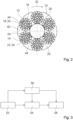
- the Figure 2 shows a schematic cross-sectional view of the rope 10.
- the rope 10 is designed as a wire rope.
- the rope 10 is designed as a cable car traction wire rope.
- the rope 10 could also be designed as a cable car hoist wire rope.
- the rope 10 comprises a rope core 20.
- the rope 10 comprises a A plurality of longitudinal elements 12, 14.
- the rope core 20 is made of a material with a lower modulus of elasticity than the longitudinal elements 12, 14.
- the rope core 20 is made of a material with a lower modulus of compression than the longitudinal elements 12, 14.
- the rope core 20 is non-metallic.
- the rope core 20 is made of a plastic.
- the rope core 20 is designed as a monolithic component.
- the rope core 20 is manufactured as an extruded component.
- the rope core 20 could also be designed and/or manufactured differently, e.g. from a stranded (PP) split fiber yarn.
- the Figure 2 The rope core 20 shown as an example has a cylindrical outer surface 26.
- the Figure 2 The rope core 20 shown as an example has a groove-free outer surface 26.
- the Figure 2 The rope core 20 shown as an example is made of solid material. However, it is also conceivable that the rope core 20 is hollow.
- the rope 10 shown as an example comprises six longitudinal elements 12, 14.
- the longitudinal elements 12, 14 are stranded around the rope core 20.
- the longitudinal elements 12, 14 are at least substantially identical to one another.
- the longitudinal elements 12, 14 are designed as wire strands.
- the wire strands each comprise a plurality of wires.
- the wires of the wire strands are made of steel.
- the wires of the wire strands are steel wires.
- the rope 10 shown as an example is a 6x36 Warrington-Seale wire strand rope.
- the rope 10 has insert elements 42, 44.
- the insert elements 42, 44 are arranged between the individual stranded longitudinal elements 12, 14.
- the insert elements 42, 44 extend helically around the rope core 20.
- the insert elements 42, 44 are made of a polymer.
- Each of the insert elements 42, 44 arranged between two adjacent longitudinal elements 12, 14 is arranged in the circumferential direction 32 of the rope 10 between two adjacent lubricant depots 16, 22
- the rope 10 has a first lubricant reservoir 16.
- the rope 10 has a second lubricant reservoir 22.
- the rope 10 has further lubricant reservoirs
- the number of lubricant depots 16, 22 of the rope 10 corresponds to the number of longitudinal elements 12, 14 (here: 6) of an innermost rope layer 34 of the rope 10.
- the lubricant depots 16, 22 are each filled with a lubricant 30 / formed by a lubricant accumulation.
- the first lubricant depot 16 is limited to a first contact area 18. In the first contact area 18, the rope core 20 and the first longitudinal element 12 touch each other.
- the first contact area 18 runs spirally around the rope core 20 (see also Fig. 5 or 7 ).
- the second lubricant reservoir 22 is limited to a second contact area 24.
- the rope core 20 and the second longitudinal element 14 touch each other.
- the second contact area 24 runs spirally around the rope core 20 (see also Fig. 5 or 7 ).
- the first lubricant reservoir 16 and the second lubricant reservoir 22 are spatially completely separated from one another. All lubricant reservoirs 16, 22 of the rope 10 are spatially completely separated from one another. All lubricant reservoirs 16, 22 of the rope 10 extend to one another without crossing.
- the lubricant 30 contained in the lubricant reservoirs 16, 22 deviates significantly from the specifications of Annex A "General Requirements for Lubricants" of the standard EN 12385-8:2002 (D).
- the lubricant 30 contained in the lubricant reservoirs 16, 22 has a friction coefficient of less than 0.2.
- the friction coefficient is determined according to the standard DIN 21258:2007-10 (item 5).
- the content of the standards DIN 21258:2007-10 and/or EN 12385-8:2002 (D), including Annex A, is hereby incorporated in its entirety by reference into this disclosure.
- the lubricant 30 also has a friction coefficient greater than 0.02.
- the lubricant 30 contained in the lubricant depots 16, 22 comprises an EP (Extreme Pressure) additive 38 (see also Fig. 7 ). All lubricant reservoirs 16, 22 contain the same lubricant 30.
- the Figure 3 shows a schematic flow diagram of a method for producing the rope 10.
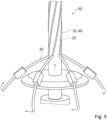
- the Figures 4 and 5 show sections of a production device 60 in operation for producing the rope 10.
- the rope core 20 is produced, for example by extrusion (see also Fig. 4 ).
- the rope core 20 could also be designed and/or manufactured differently, e.g., from a stranded (PP) split fiber yarn.
- the rope core 20 can be produced in a cylindrical shape or provided with spiral grooves on a cylindrical surface.
- the lubricant 30 is applied in regions, in particular in strips, to an outer surface 26 of the rope core 20.
- the lubricant 30 is applied to the rope core 20 during a longitudinal movement of the rope core 20, so that adhering lubricant strips 46 form on the outer surface 26 of the rope core 20 (see also Figures 4 or 5 ).
- the applied lubricant strips 46 then spiral around the rope core 20.
- the lubricant 30 is applied to a rear side 36 of the longitudinal elements 12, 14 forming the innermost rope layer 34 of the rope 10, facing the rope core 20.
- the lubricant 30 is applied to the rope core 20 and/or to the longitudinal elements 12, 14 by means of lubricant nozzles 40 (see also Figures 4 or 5 ).
- the lubricant nozzles 40 dispensing the lubricant 30 are preferably rotated uniformly around the longitudinally moving rope core 20. If the rope core 20 has been provided with grooves 48 spirally encircling the rope core 20 in the previous manufacturing step 52, the lubricant 30 is then introduced into the grooves 48 of the rope core 20 spirally encircling the rope core 20 by means of the lubricant nozzles 40 in the current manufacturing step 56. In at least one further manufacturing step 58, immediately after the application of the lubricant 30, the longitudinal elements 12, 14 are stranded spirally around the rope core 20 and are thereby brought into contact with the rope core 20. In the manufacturing step 58, the insert elements 42, 44 are also stranded around the rope core 20 together with the longitudinal elements 12, 14 at the same time.
- the Figure 6 shows a schematic cross-sectional view of an alternative rope 10', which differs from the rope 10 of the Figure 2 differs only in the design of the cable core 20'.
- the alternative cable core 20' has grooves 48 running spirally around the alternative cable core 20'.
- Each of the longitudinal elements 12, 14 is inserted into one of the grooves 48.
- the grooves 48 each have a groove cross-sectional shape that at least substantially corresponds to an outer cross-sectional shape of the associated longitudinal element 12, 14.
- the lubricant depots 16, 22 are each arranged within a groove 48 of the grooves 48.
- the grooves 48 of the alternative cable core 20' spatially delimit the respective lubricant depots 16, 22 in the circumferential direction 32 of the alternative cable core 20'.
- the Figure 7 shows schematically a side view of a partial section of an alternative rope core 20' having the grooves 48 ("naked") with the lubricant 30 introduced into the grooves 48.
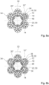
- the Figures 8a and 8b show schematic plan views of cross sections of further alternative ropes 10", 10'", which differ from the ropes 10, 10' of the preceding figures by the design of the longitudinal elements 12, 14 and the rope core 20".
- the longitudinal elements 12, 14 of the first further alternative rope 10" are in the Figure 8a designed as 21-filler wire strands.
- the longitudinal elements 12, 14 of the second alternative rope 10′′′ are in the Figure 8b For example, they are designed as 29-filler wire strands.
- the further alternative ropes 10", 10" are designed without insert elements 42, 44. Alternatively, however, the further alternative ropes 10", 10" could also have insert elements 42, 44 between the longitudinal elements 12, 14.
- the further alternative ropes 10", 10" each have a further alternative rope core 20".
- the further alternative rope core 20" has 26 grooves 48 on its outer surface.
- the grooves 48 of the further alternative rope core 20" are designed differently in shape and number than the grooves 48 of the alternative rope core 20'.
- the Figure 9 shows a schematic cross-sectional view of a first other alternative rope 10a, which differs from the rope 10 of the Figure 2 only by the arrangement of lubricant reservoirs 16, 16a.
- the Figure 9 to the Figure 2 The difference in lubricant depot arrangements shown can also be applied to the embodiments of the Figures 6 to 8b
- the data in the Figure 9 The rope 10a shown as an example comprises six longitudinal elements 12, 14.
- the rope 10a has insert elements 42, 44.
- the insert elements 42, 44 are arranged between the individual stranded longitudinal elements 12, 14.
- the rope 10a has a first lubricant depot 16a.
- the rope 10a has a second lubricant depot 22a.
- the rope 10a has further lubricant depots.
- the number of lubricant depots 16a, 22a of the rope 10a corresponds to the number of insert elements 44, 42 (here: 6) of the rope 10a.
- the lubricant depots 16a, 22a are each filled with a lubricant 30 / formed by a lubricant accumulation.
- the first lubricant depot 16a is limited to a first contact area 18a. In the first contact area 18a, the rope core 20 and the first insert element 42 touch each other.
- the second lubricant reservoir 22a is limited to a second contact area 24a. In the second contact area 24a, the rope core 20 and the second insert element 44 touch each other.
- the first lubricant reservoir 16a and the second lubricant reservoir 22a are spatially completely separated from each other.
- the Figure 10 shows a schematic cross-sectional view of a second alternative rope 10b, which differs from the rope 10 of the Figure 2 only differs in the arrangement and number of lubricant reservoirs 16, 16a.
- Figure 10 to the Figure 2 The difference in lubricant depot arrangements and lubricant depot numbers shown can also be applied to the embodiments of the Figures 6 to 8b
- the data in the Figure 10 The rope 10b shown as an example comprises six longitudinal elements 12, 14.
- the rope 10b has insert elements 42, 44.
- the insert elements 42, 44 are arranged between the individual stranded longitudinal elements 12, 14.
- the rope 10b has a first lubricant reservoir 16.
- the rope 10b has a further first Lubricant depot 16a.
- the rope 10b has a second lubricant depot 22.
- the rope 10b has a further second lubricant depot 22a.
- the number of lubricant depots 16, 16a, 22, 22a of the rope 10b corresponds to the sum of the longitudinal elements 12, 14 of an innermost rope layer 34 of the rope 10 and the insert elements 42, 44 of the rope 10b (here a total of 12).
- the lubricant depots 16, 16a, 22, 22a are each filled with a lubricant 30/formed by a lubricant accumulation.
- the first lubricant depot 16 is limited to a first contact area 18. In the first contact area 18, the rope core 20 and the first longitudinal element 12 touch each other.
- the further first lubricant depot 16a is limited to a further first contact area 18a.
- the second lubricant depot 22 is limited to a second contact area 24.
- the rope core 20 and the second longitudinal element 14 touch each other.
- the further second lubricant depot 22a is limited to a further second contact area 24a.
- the rope core 20 and the second insert element 44 touch each other.
- the lubricant depots 16, 16a, 22, 22a are all spatially completely separated from one another.
Landscapes
- Chemical & Material Sciences (AREA)
- Oil, Petroleum & Natural Gas (AREA)
- Lift-Guide Devices, And Elevator Ropes And Cables (AREA)
- Ropes Or Cables (AREA)
Applications Claiming Priority (1)
| Application Number | Priority Date | Filing Date | Title |
|---|---|---|---|
| DE102023131360.6A DE102023131360A1 (de) | 2023-11-10 | 2023-11-10 | Seil mit internen Schmiermitteldepots, Seilbahn mit dem Seil und Verfahren zur Herstellung des Seils |
Publications (1)
| Publication Number | Publication Date |
|---|---|
| EP4553220A1 true EP4553220A1 (fr) | 2025-05-14 |
Family
ID=93460621
Family Applications (1)
| Application Number | Title | Priority Date | Filing Date |
|---|---|---|---|
| EP24211836.2A Pending EP4553220A1 (fr) | 2023-11-10 | 2024-11-08 | Corde avec dépôts de lubrifiant internes, téléphérique avec la corde et procédé de fabrication de la corde |
Country Status (2)
| Country | Link |
|---|---|
| EP (1) | EP4553220A1 (fr) |
| DE (1) | DE102023131360A1 (fr) |
Citations (6)
| Publication number | Priority date | Publication date | Assignee | Title |
|---|---|---|---|---|
| JPS56120798A (en) * | 1980-02-28 | 1981-09-22 | Mitsubishi Electric Corp | Traction elevator apparatus |
| CA1163879A (fr) * | 1980-12-27 | 1984-03-20 | Tatsuo Yoshida | Cable metallique |
| WO1996011245A1 (fr) * | 1994-10-08 | 1996-04-18 | Exxon Research And Engineering Company | Graisse lubrifiante destinee a des engrenages decouverts, a des cables ainsi qu'a toute autre surface metallique exposee |
| KR20000065758A (ko) * | 1999-04-08 | 2000-11-15 | 홍영철 | 와이어 로프 코어 |
| US20130318937A1 (en) * | 2012-05-31 | 2013-12-05 | Tokyo Rope Manufactuting Co., Ltd. | Hybrid core rope |
| US20190062992A1 (en) * | 2016-06-16 | 2019-02-28 | Kone Corporation | Steel wire rope, elevator provided with steel wire rope, lubricant for steel wire rope, and use of lubricant for lubricating the steel wire rope |
Family Cites Families (6)
| Publication number | Priority date | Publication date | Assignee | Title |
|---|---|---|---|---|
| US2136865A (en) * | 1936-10-22 | 1938-11-15 | Malcolm W Reed | Wire rope |
| AT407761B (de) * | 1989-10-31 | 2001-06-25 | Teufelberger Seil Ges M B H | Drahtseil |
| DE4232012C2 (de) * | 1992-09-24 | 1994-11-10 | Thyssen Draht Ag | Stahlseil |
| DE202011109156U1 (de) * | 2011-12-15 | 2013-03-18 | Pfeifer Drako Drahtseilwerk Gmbh & Co. Kg | Drahtseil |
| DE202015106536U1 (de) * | 2015-12-01 | 2016-01-18 | Pfeifer Drako Drahtseilwerk Gmbh & Co. Kg | Drahtseil mit in das Seilgefüge integriertem Kunststoff |
| CN114960242B (zh) * | 2022-05-11 | 2024-08-20 | 昆山东岸海洋工程有限公司 | 一种多股钢丝绳增加高柔性高填充系数钢丝绳 |
-
2023
- 2023-11-10 DE DE102023131360.6A patent/DE102023131360A1/de active Pending
-
2024
- 2024-11-08 EP EP24211836.2A patent/EP4553220A1/fr active Pending
Patent Citations (6)
| Publication number | Priority date | Publication date | Assignee | Title |
|---|---|---|---|---|
| JPS56120798A (en) * | 1980-02-28 | 1981-09-22 | Mitsubishi Electric Corp | Traction elevator apparatus |
| CA1163879A (fr) * | 1980-12-27 | 1984-03-20 | Tatsuo Yoshida | Cable metallique |
| WO1996011245A1 (fr) * | 1994-10-08 | 1996-04-18 | Exxon Research And Engineering Company | Graisse lubrifiante destinee a des engrenages decouverts, a des cables ainsi qu'a toute autre surface metallique exposee |
| KR20000065758A (ko) * | 1999-04-08 | 2000-11-15 | 홍영철 | 와이어 로프 코어 |
| US20130318937A1 (en) * | 2012-05-31 | 2013-12-05 | Tokyo Rope Manufactuting Co., Ltd. | Hybrid core rope |
| US20190062992A1 (en) * | 2016-06-16 | 2019-02-28 | Kone Corporation | Steel wire rope, elevator provided with steel wire rope, lubricant for steel wire rope, and use of lubricant for lubricating the steel wire rope |
Non-Patent Citations (3)
| Title |
|---|
| DER INHALT DER NORMEN DIN, vol. 21258, pages 2007 - 10 |
| EN, 2002, pages 12385 - 8 |
| VON DEN VORGABENDES ANHANGS A: "Allgemeine Anforderungen an Schmierstoffe", DER NORM EN, 2002, pages 12385 - 8 |
Also Published As
| Publication number | Publication date |
|---|---|
| DE102023131360A1 (de) | 2025-05-15 |
Similar Documents
| Publication | Publication Date | Title |
|---|---|---|
| EP1724226B1 (fr) | Ascenseur | |
| DE69433048T2 (de) | Hebeseil | |
| EP0995832B1 (fr) | Câble commis en fibres synthétiques | |
| CH644413A5 (de) | Seil. | |
| EP3499083B1 (fr) | Douille à ressort, cylindre, unité piston-cylindre et procédé de fabrication d'une unité piston-cylindre | |
| DE2202823C3 (de) | Drahtseil mit einer Kunststoff- oder Kautschuklage | |
| DE2853661C2 (de) | Kunstfaserseil | |
| EP3255206B1 (fr) | Élément intermédiaire pour un câble métallique épissé | |
| DE2903854A1 (de) | Dreikantlitzenseil | |
| EP4553220A1 (fr) | Corde avec dépôts de lubrifiant internes, téléphérique avec la corde et procédé de fabrication de la corde | |
| EP3670960A1 (fr) | Courroie | |
| DE202011109156U1 (de) | Drahtseil | |
| EP3655583B1 (fr) | Câble comprenant une section comprenant une épissure longue et procédé d'épissurage d'un câble | |
| WO2019016368A1 (fr) | Section de câble et procédé d'épissurage d'un câble formant un câble de transport des personnes | |
| DE102023105084A1 (de) | Seil, Seilseele, Seilinstallation und Verfahren | |
| DE4232012C2 (de) | Stahlseil | |
| DE112020007718T5 (de) | Hochfeste Faseranordnung, Seil und Seilstruktur | |
| DE3410970C2 (fr) | ||
| EP0125505A2 (fr) | Câblé de renforcement en acier pour produits élastomères | |
| DE10225699B3 (de) | Drahtseil, insbesondere als Festigkeitsträger für Reifen oder Hochdruckschläuche | |
| EP0111797B1 (fr) | Câble métallique à plusieurs couches de torons | |
| DE2100137A1 (fr) | ||
| EP1498542B1 (fr) | Elément longitudinal en mouvement, en particulier pour un ascenseur ou une grue ou analogue | |
| DE19811412B4 (de) | Fördergurt | |
| EP4587637A1 (fr) | Câble métallique non rotatif, son procédé de production et dispositif de levage comprenant un entraînement de tambour |
Legal Events
| Date | Code | Title | Description |
|---|---|---|---|
| PUAI | Public reference made under article 153(3) epc to a published international application that has entered the european phase |
Free format text: ORIGINAL CODE: 0009012 |
|
| STAA | Information on the status of an ep patent application or granted ep patent |
Free format text: STATUS: THE APPLICATION HAS BEEN PUBLISHED |
|
| AK | Designated contracting states |
Kind code of ref document: A1 Designated state(s): AL AT BE BG CH CY CZ DE DK EE ES FI FR GB GR HR HU IE IS IT LI LT LU LV MC ME MK MT NL NO PL PT RO RS SE SI SK SM TR |
|
| STAA | Information on the status of an ep patent application or granted ep patent |
Free format text: STATUS: REQUEST FOR EXAMINATION WAS MADE |
|
| 17P | Request for examination filed |
Effective date: 20250702 |